Sign In
Upload
Manuals
Brands
Fronius Manuals
Welding System
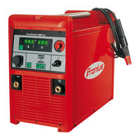
TransPocket 5000 CEL
Fronius TransPocket 5000 CEL Manuals
Manuals and User Guides for Fronius TransPocket 5000 CEL. We have
3
Fronius TransPocket 5000 CEL manuals available for free PDF download: Operating Instructions Manual, Operating Instructions & Spare Parts
Fronius TransPocket 5000 CEL Operating Instructions Manual (172 pages)
Brand:
Fronius
| Category:
Welding System
| Size: 6.44 MB
Table of Contents
Deutsch
3
Table of Contents
3
Allgemeines
5
Sicherheitsvorschriften
5
Erklärung Sicherheitshinweise
5
Bestimmungsgemäße Verwendung
6
Umgebungsbedingungen
6
Verpflichtungen des Betreibers
6
Verpflichtungen des Personals
7
Netzanschluss
7
Fehlerstrom-Schutzschalter
7
Selbst- und Personenschutz
7
Angaben zu Geräuschemissions-Werten
8
Gefahr durch Schädliche Gase und Dämpfe
8
Gefahr durch Funkenflug
9
Gefahren durch Netz- und Schweißstrom
9
Vagabundierende Schweißströme
10
EMV Geräte-Klassifizierungen
11
EMV-Maßnahmen
11
EMF-Maßnahmen
12
Besondere Gefahrenstellen
12
Gefahr durch Schutzgas-Flaschen
13
Anforderung an das Schutzgas
13
Sicherheitsmaßnahmen IM Normalbetrieb
14
Sicherheitsmaßnahmen am Aufstellort und Beim Transport
14
Inbetriebnahme, Wartung und Instandsetzung
15
Sicherheitstechnische Überprüfung
15
Entsorgung
16
Sicherheitskennzeichnung
16
Datensicherheit
16
Urheberrecht
16
Einsatzgebiete
17
Allgemeines
17
Gerätekonzept
17
Prinzip der Digitalen Gerätefamilie
17
Bedienelemente und Anschlüsse
19
Allgemeines
19
Beschreibung des Bedienpanels
19
Anschlüsse
21
Fernbdienung TR 3000
22
Fernbdienung TP
24
Fernbdienung TR 4000
24
Fernbdienung TR 1000 / TR 1100
24
Fernbdienung TR 2000
24
Optionen
27
Verteiler „Local-Net Passiv
27
Verteiler „Local-Net Aktiv
27
Polwender
28
Vor der Inbetriebnahme
29
Sicherheit
29
Bestimmungsgemässe Verwendung
29
Aufstellbestimmungen
29
Netzanschluss
29
Fahrwagen Everywhere Montieren
31
Sicherheit
31
Stromquelle auf Fahrwagen Montieren
31
Griffteil an der Stromquelle Montieren
32
Bedienung des Griffteiles
33
Vorbereitung
34
Sicherheit
34
Stabelektroden-Schweißen
34
Funktion Hot-Start
35
Funktion Eln (Kennlinienauswahl)
35
Funktion Anti-Stick
37
WIG-Schweißen
39
Sicherheit
39
Option TIG-Comfort-Stop
40
Das Setup-Menü Verlassen
42
Parameter Ändern
42
In das Setup-Menü für Parameter Verfahren Einsteigen
42
Allgemeines
42
Das Setup-Menü: Ebene 1
42
Parameter
43
Stabelektroden-Schweißen
43
WIG-Schweißen
43
Das Setup-Menü: Ebene 2
44
Allgemeines
44
Parameter Ändern
44
Das Setup-Menü Verlassen
44
Allgemeines
45
Parameter 2Nd
45
Schweißkreis-Widerstand R Ermitteln
46
Allgemeines
46
Schweißkreis-Induktivität L Anzeigen
47
Fehlerdiagnose, Fehlerbehebung
48
Sicherheit
48
Angezeigte Service-Codes
48
Stromquelle TP 4000 CEL / TP 5000 CEL
49
Entsorgung
52
Alle 6 Monate
52
Bei jeder Inbetriebnahme
52
Alle 2 Monate
52
Pflege, Wartung und Entsorgung
52
Allgemeines
52
Durchschnittliche Verbrauchswerte Beim Schweißen
53
Durchschnittlicher Drahtelektroden-Verbrauch Beim MIG/MAG-Schweißen
53
Durchschnittlicher Schutzgas-Verbrauch Beim MIG/MAG-Schweißen
53
Durchschnittlicher Schutzgas-Verbrauch Beim WIG-Schweißen
53
Tp 4000 Cel MV
54
Technische Daten
54
Allgemeines
54
Tp 4000 Cel
54
Tp 5000 Cel
55
Tp 5000 Cel MV
56
Übersicht mit Kritischen Rohstoffen, Produktionsjahr des Gerätes
57
English
59
Explanation of Safety Notices
61
General
61
Safety Rules
61
Environmental Conditions
62
Obligations of Personnel
62
Obligations of the Operator
62
Proper Use
62
Mains Connection
63
Protecting Yourself and Others
63
Residual Current Protective Device
63
Danger from Toxic Gases and Vapours
64
Noise Emission Values
64
Danger from Flying Sparks
65
Risks from Mains Current and Welding Current
65
EMC Device Classifications
66
Meandering Welding Currents
66
EMC Measures
67
EMF Measures
67
Specific Hazards
67
Requirement for the Shielding Gas
68
Danger from Shielding Gas Cylinders
69
Safety Measures at the Installation Location and During Transport
69
Commissioning, Maintenance and Repair
70
Safety Measures in Normal Operation
70
Data Protection
71
Disposal
71
Safety Inspection
71
Safety Symbols
71
Copyright
72
Application Areas
73
Device Concept
73
General
73
Principle of the Digital Series
73
Control Elements and Connections
74
Description of the Control Panel
74
General
74
Connections
76
TR 2000 Remote Control
77
TR 3000 Remote Control
77
TR 1000 / TR 1100 Remote Control
79
TR 4000 Remote Control
79
TP 08 Remote Control
80
Localnet Active" Distributor
82
Localnet Passive" Distributor
82
Options
82
Polarity Reverser
83
Before Commissioning
84
Mains Connection
84
Proper Use
84
Safety
84
Setup Regulations
84
Fitting the Power Source to the Trolley
86
Mounting the Everywhere Trolley
86
Safety
86
Fitting the Handle to the Power Source
87
Operating the Handle
88
MMA Welding
89
Preparation
89
Safety
89
Eln Function (Characteristic Selection)
90
Hotstart Function
90
Anti-Stick Function
92
Safety
93
TIG Welding
93
TIG Comfort Stop Option
94
Accessing the Setup Menu for Process Parameters
96
Changing Welding Parameters
96
Exiting the Setup Menu
96
General
96
Setup Menu: Level 1
96
MMA Welding
97
Parameters
97
TIG Welding
97
Changing Welding Parameters
98
Exiting the Setup Menu
98
General
98
Setup Menu: Level 2
98
2Nd Parameter
99
General
99
General
100
Measuring the Welding Circuit Resistance R
100
Measuring Welding Circuit Resistance R
100
Displaying Welding Circuit Inductivity L
101
Displayed Service Codes
102
Safety
102
Troubleshooting
102
At Every Start-Up
106
Care, Maintenance and Disposal
106
Disposal
106
Every 2 Months
106
Every 6 Months
106
General
106
Average Consumption Values During Welding
107
Average Shielding Gas Consumption During MIG/MAG Welding
107
Average Shielding Gas Consumption During TIG Welding
107
Average Wire Electrode Consumption During MIG/MAG Welding
107
General
108
Technical Data
108
Tp 4000 Cel
108
Tp 4000 Cel MV
108
Tp 5000 Cel
109
Tp 5000 Cel MV
110
Français
113
Consignes de Sécurité
115
Explication des Consignes de Sécurité
115
Généralités
115
Conditions Environnementales
116
Obligations de L'exploitant
116
Utilisation Conforme À la Destination
116
Couplage Au Réseau
117
Disjoncteur À Courant Résiduel
117
Obligations du Personnel
117
Protection de L'utilisateur Et des Personnes
117
Données Relatives Aux Valeurs des Émissions Sonores
118
Risque Lié Aux Gaz Et Aux Vapeurs Nocifs
118
Risque Lié Au Courant D'alimentation Et À L'intensité de Soudage
119
Risques Liés À la Projection D'étincelles
119
Classification CEM des Appareils
121
Intensités de Soudage Vagabondes
121
Mesures CEM
121
Mesures Liées Aux Champs Électromagnétiques
122
Sources de Risques Particulières
122
Exigences Liées Au Gaz de Protection
123
Mesures de Sécurité Sur Le Lieu D'installation Et Lors du Transport
124
Risque Lié Aux Bouteilles de Gaz de Protection
124
Mesures de Sécurité en Mode de Fonctionnement Normal
125
Contrôle Technique de Sécurité
126
Marquage de Sécurité
126
Mise en Service, Maintenance Et Remise en État
126
Élimination
126
Droits D'auteur
127
Sûreté des Données
127
Concept D'appareil
128
Domaines D'utilisation
128
Généralités
128
Principe de Fonctionnement de la Série D'appareils Numériques
128
Description du Panneau de Commande
130
Généralités
130
Éléments de Commande Et Connexions
130
Commande À Distance TR 2000
133
Connecteurs
133
Commande À Distance TR 3000
134
Commande À Distance TR 4000
135
Commande À Distance TR 1000 / TR 1100
136
Commande À Distance TP 08
137
Options
138
Répartiteur " Localnet Actif
138
Répartiteur " Localnet Passif
138
Commutateur de Pôle
139
Avant la Mise en Service
140
Couplage Au Réseau
140
Instructions D'installation
140
Sécurité
140
Utilisation Conforme À la Destination
140
Monter la Source de Courant Sur Le Chariot
142
Monter Le Chariot Everywhere
142
Sécurité
142
Monter la Poignée Sur la Source de Courant
143
Utilisation de la Poignée
144
Préparation
145
Soudage Manuel À L'électrode Enrobée
145
Soudage À Électrode Enrobée
145
Sécurité
145
Fonction Eln (Sélection de la Courbe Caractéristique)
146
Fonction Hot-Start
146
Fonction Anti-Stick
149
Soudage TIG
150
Sécurité
150
Option TIG Comfort Stop
151
Entrer Dans Le Menu Setup Pour Accéder Aux Paramètres ProcéDés
153
Généralités
153
Menu Setup : Niveau 1
153
Modifier Les Paramètres
153
Quitter Le Menu Setup
153
Paramètres
154
Soudage Manuel À L'électrode Enrobée
154
Soudage TIG
154
Généralités
155
Menu Setup : Niveau 2
155
Modifier Les Paramètres
155
Quitter Le Menu Setup
155
Généralités
156
Paramètres 2Nd
156
Détermination de la Résistance R du Circuit de Soudage
158
Déterminer la Résistance R du Circuit de Soudage
158
Généralités
158
Afficher L'inductance L du Circuit de Soudage
159
Codes de Service Affichés
160
Diagnostic D'erreur, Élimination de L'erreur
160
Sécurité
160
Sources de Courant TP 4000 CEL / TP 5000 CEL
161
Généralités
164
Maintenance, Entretien Et Élimination
164
Tous Les 2 Mois
164
Tous Les 6 Mois
164
À Chaque Mise en Service
164
Élimination des Déchets
164
Consommation Moyenne de Fil-Électrode Pour Le Soudage MIG/MAG
165
Consommation Moyenne de Gaz de Protection Pour Le Soudage MIG/MAG
165
Consommation Moyenne de Gaz de Protection Pour Le Soudage TIG
165
Valeurs Moyennes de Consommation Pendant Le Soudage
165
Caractéristiques Techniques
166
Généralités
166
Tp 4000 Cel
166
Tp 4000 Cel MV
166
Tp 5000 Cel
167
Tp 5000 Cel MV
168
Aperçu des Matières Premières Critiques, Année de Production de L'appareil
169
Advertisement
Fronius TransPocket 5000 CEL Operating Instructions Manual (160 pages)
Rod electrode power source
Brand:
Fronius
| Category:
Portable Generator
| Size: 11.79 MB
Table of Contents
Deutsch
5
Table of Contents
5
Sicherheitsvorschriften
7
Erklärung Sicherheitshinweise
7
Allgemeines
7
Bestimmungsgemäße Verwendung
8
Umgebungsbedingungen
8
Verpflichtungen des Betreibers
8
Verpflichtungen des Personals
8
Netzanschluss
9
Fehlerstrom-Schutzschalter
9
Selbst- und Personenschutz
9
Angaben zu Geräuschemissions-Werten
10
Gefahr durch Schädliche Gase und Dämpfe
10
Gefahr durch Funkenflug
11
Gefahren durch Netz- und Schweißstrom
11
Vagabundierende Schweißströme
12
EMV Geräte-Klassifizierungen
12
EMV-Maßnahmen
13
EMF-Maßnahmen
13
Besondere Gefahrenstellen
13
Anforderung an das Schutzgas
15
Gefahr durch Schutzgas-Flaschen
15
Sicherheitsmaßnahmen am Aufstellort und Beim Transport
15
Sicherheitsmaßnahmen IM Normalbetrieb
16
Inbetriebnahme, Wartung und Instandsetzung
17
Sicherheitstechnische Überprüfung
17
Entsorgung
17
Sicherheitskennzeichnung
17
Datensicherheit
18
Urheberrecht
18
Allgemeines
19
Prinzip der Digitalen Gerätefamilie
19
Gerätekonzept
19
Einsatzgebiete
19
Bedienelemente und Anschlüsse
20
Allgemeines
20
Beschreibung des Bedienpanels
20
Anschlüsse
22
Fernbdienung TR 2000
23
Fernbdienung TR 3000
23
Fernbdienung TR 4000
24
Fernbdienung TR 1000 / TR 1100
25
Fernbdienung TP 08
25
Verteiler „Local-Net Passiv
27
Verteiler „Local-Net Aktiv
27
Polwender
28
Optionen
27
Vor der Inbetriebnahme
29
Sicherheit
29
Bestimmungsgemässe Verwendung
29
Aufstellbestimmungen
29
Netzanschluss
29
Fahrwagen Everywhere Montieren
31
Sicherheit
31
Stromquelle auf Fahrwagen Montieren
31
Griffteil an der Stromquelle Montieren
32
Bedienung des Griffteiles
33
Stabelektroden-Schweißen
34
Sicherheit
34
Vorbereitung
34
Funktion Hot-Start
35
Funktion Eln (Kennlinienauswahl)
35
Funktion Anti-Stick
37
WIG-Schweißen
38
Sicherheit
38
Option TIG-Comfort-Stop
39
Das Setup-Menü: Ebene 1
41
Allgemeines
41
In das Setup-Menü für Parameter Verfahren Einsteigen
41
Parameter Ändern
41
Das Setup-Menü Verlassen
41
Parameter
42
Stabelektroden-Schweißen
42
WIG-Schweißen
42
Das Setup-Menü: Ebene 2
43
Allgemeines
43
Parameter Ändern
43
Das Setup-Menü Verlassen
43
Parameter 2Nd
44
Allgemeines
44
Schweißkreis-Widerstand R Ermitteln
45
Allgemeines
45
Schweißkreis-Induktivität L Anzeigen
46
Fehlerdiagnose, Fehlerbehebung
47
Sicherheit
47
Angezeigte Service-Codes
47
Stromquelle TP 4000 CEL / TP 5000 CEL
48
Pflege, Wartung und Entsorgung
51
Allgemeines
51
Bei jeder Inbetriebnahme
51
Alle 2 Monate
51
Alle 6 Monate
51
Entsorgung
51
Technische Daten
52
Allgemeines
52
Tp 4000 Cel
52
Tp 4000 Cel MV
52
Tp 5000 Cel
53
Tp 5000 Cel MV
54
English
57
Safety Rules
59
Explanation of Safety Notices
59
General
59
Proper Use
59
Environmental Conditions
60
Obligations of the Operator
60
Obligations of Personnel
60
Mains Connection
60
Residual Current Protective Device
61
Protecting Yourself and Others
61
Noise Emission Values
61
Danger from Toxic Gases and Vapours
62
Danger from Flying Sparks
62
Risks from Mains Current and Welding Current
63
Meandering Welding Currents
64
EMC Device Classifications
64
EMC Measures
64
EMF Measures
65
Specific Hazards
65
Requirement for the Shielding Gas
66
Danger from Shielding Gas Cylinders
66
Safety Measures at the Installation Location and During Transport
67
Safety Measures in Normal Operation
67
Commissioning, Maintenance and Repair
68
Safety Inspection
68
Disposal
69
Safety Symbols
69
Data Protection
69
Copyright
69
General
70
Principle of the Digital Series
70
Device Concept
70
Application Areas
70
Control Elements and Connections
71
General
71
Description of the Control Panel
71
Connections
73
TR 2000 Remote Control
74
TR 3000 Remote Control
74
TR 4000 Remote Control
75
TR 1000 / TR 1100 Remote Control
76
TP 08 Remote Control
76
Options
78
Localnet Passive" Distributor
78
Localnet Active" Distributor
78
Polarity Reverser
79
Before Commissioning
80
Safety
80
Proper Use
80
Setup Regulations
80
Mains Connection
80
Mounting the Everywhere Trolley
81
Safety
81
Fitting the Power Source to the Trolley
81
Fitting the Handle to the Power Source
82
Operating the Handle
83
MMA Welding
84
Safety
84
Preparation
84
Hotstart Function
85
Eln Function (Characteristic Selection)
85
Anti-Stick Function
87
TIG Welding
88
Safety
88
TIG Comfort Stop Option
89
Setup Menu: Level 1
91
General
91
Accessing the Setup Menu for Process Parameters
91
Changing Welding Parameters
91
Exiting the Setup Menu
91
Parameters
92
MMA Welding
92
TIG Welding
92
Setup Menu: Level 2
93
General
93
Changing Welding Parameters
93
Exiting the Setup Menu
93
2Nd Parameter
94
General
94
Measuring Welding Circuit Resistance R
95
General
95
Measuring the Welding Circuit Resistance R
95
Displaying Welding Circuit Inductivity L
96
Troubleshooting
97
Safety
97
Displayed Service Codes
97
TP 4000 CEL / TP 5000 CEL Power Source
98
Care, Maintenance and Disposal
101
General
101
At Every Start-Up
101
Every 2 Months
101
Every 6 Months
101
Disposal
101
Technical Data
102
General
102
Tp 4000 Cel
102
Tp 4000 Cel MV
102
Tp 5000 Cel
103
Tp 5000 Cel MV
104
Français
107
Consignes de Sécurité
109
Explication des Consignes de Sécurité
109
Généralités
109
Utilisation Conforme À la Destination
110
Conditions Environnementales
110
Obligations de L'exploitant
110
Obligations du Personnel
111
Couplage Au Réseau
111
Disjoncteur À Courant Résiduel
111
Protection de L'utilisateur Et des Personnes
111
Données Relatives Aux Valeurs des Émissions Sonores
112
Risque Lié Aux Gaz Et Aux Vapeurs Nocifs
112
Risques Liés À la Projection D'étincelles
113
Risques Liés Au Courant D'alimentation Et À L'intensité de Soudage
113
Intensités de Soudage Vagabondes
114
Classification CEM des Appareils
115
Mesures Relatives À la CEM
115
Mesures Liées Aux Champs Électromagnétiques
116
Emplacements Particulièrement Dangereux
116
Exigences Liées Au Gaz de Protection
117
Risque Lié Aux Bouteilles de Gaz de Protection
117
Mesures de Sécurité Sur Le Lieu D'installation Et Lors du Transport
118
Mesures de Sécurité en Mode de Fonctionnement Normal
118
Mise en Service, Maintenance Et Remise en État
119
Contrôle Technique de Sécurité
119
Élimination
120
Marquage de Sécurité
120
Sûreté des Données
120
Droits D'auteur
120
Généralités
121
Principe de Fonctionnement de la Série D'appareils Numériques
121
Concept D'appareil
121
Domaines D'utilisation
121
Éléments de Commande Et Connexions
122
Généralités
122
Description du Panneau de Commande
122
Connecteurs
124
Commande À Distance TR 2000
125
Commande À Distance TR 3000
125
Commande À Distance TR 4000
127
Commande À Distance TR 1000 / TR 1100
127
Commande À Distance TP 08
128
Options
130
Répartiteur " Localnet Passif
130
Répartiteur " Localnet Actif
130
Commutateur de Pôle
131
Avant la Mise en Service
132
Sécurité
132
Utilisation Conforme À la Destination
132
Instructions D'installation
132
Couplage Au Réseau
132
Monter Le Chariot Everywhere
134
Sécurité
134
Monter la Source de Courant Sur Le Chariot
134
Monter la Poignée Sur la Source de Courant
135
Utilisation de la Poignée
136
Soudage À Électrode Enrobée
137
Sécurité
137
Préparation
137
Soudage Manuel À L'électrode Enrobée
137
Fonction Hot-Start
138
Fonction Eln (Sélection de la Courbe Caractéristique)
138
Fonction Anti-Stick
140
Soudage TIG
141
Sécurité
141
Option TIG Comfort Stop
142
Menu Setup : Niveau 1
144
Généralités
144
Entrer Dans Le Menu Setup Pour Accéder Aux Paramètres ProcéDés
144
Modifier Les Paramètres
144
Quitter Le Menu Setup
144
Paramètres
145
Soudage Manuel À L'électrode Enrobée
145
Soudage TIG
145
Menu Setup : Niveau 2
146
Généralités
146
Modifier Les Paramètres
146
Quitter Le Menu Setup
146
Paramètres 2Nd
147
Généralités
147
Détermination de la Résistance R du Circuit de Soudage
148
Généralités
148
Déterminer la Résistance R du Circuit de Soudage
148
Afficher L'inductance L du Circuit de Soudage
149
Diagnostic D'erreur, Élimination de L'erreur
150
Sécurité
150
Codes de Service Affichés
150
Sources de Courant TP 4000 CEL / TP 5000 CEL
151
Maintenance, Entretien Et Élimination
154
Généralités
154
À Chaque Mise en Service
154
Tous Les 2 Mois
154
Tous Les 6 Mois
154
Élimination des Déchets
154
Caractéristiques Techniques
155
Généralités
155
Tp 4000 Cel
155
Tp 4000 Cel MV
155
Tp 5000 Cel
156
Tp 5000 Cel MV
157
Fronius TransPocket 5000 CEL Operating Instructions & Spare Parts (163 pages)
Brand:
Fronius
| Category:
Welding System
| Size: 10.23 MB
Table of Contents
Deutsch
17
Table of Contents
17
Allgemeines
19
Prinzip der Digitalen Gerätefamilie
19
Gerätekonzept
19
Einsatzgebiete
19
Beschreibung des Bedienpanels
20
Allgemeines
20
Anschlüsse
23
Stromquelle TP 4000 CEL / TP 5000 CEL
23
Fernbedienung TR 3000
24
Fernbedienung TR 1000 / TR 1100
25
Fernbedienung TR 4000
25
Fernbedienung TP 08
26
Verteiler „Localnet Passiv
28
Polwender
29
Optionen
28
Vor der Inbetriebnahme
30
Allgemeines
30
Bestimmungsgemässe Verwendung
30
Aufstellbestimmungen
30
Netzanschluss
30
Fahrwagen „Everywhere" Montieren
31
Allgemeines
31
Stromquelle auf Fahrwagen Montieren
31
Griffteil an der Stromquelle Montieren
32
Bedienung des Griffteiles
33
Stabelektroden-Schweißen
34
Allgemeines
34
Vorbereitung
34
Funktion Hot-Start
35
Funktion Eln (Kennlinien-Auswahl)
35
Funktion Anti-Stick
37
WIG-Schweißen
38
Allgemeines
38
Vorbereitung
38
Option TIG-Comfort-Stop
40
Das Setup-Menü: Ebene 1
41
Allgemeines
41
In das Setup-Menü für Parameter Verfahren Einsteigen
41
Parameter Ändern
41
Das Setup-Menü Verlassen
41
Parameter
42
Stabelektroden-Schweißen
42
WIG-Schweißen
42
Das Setup-Menü: Ebene 2
43
Allgemeines
43
Parameter Ändern
43
Das Setup-Menü Verlassen
43
Parameter 2Nd
44
Allgemeines
44
Schweißkreis-Widerstand R Ermitteln
45
Allgemeines
45
Schweißkreis-Induktivität L Anzeigen
46
Fehlerdiagnose und Fehlerbehebung
47
Allgemeines
47
Angezeigte Service-Codes
48
Stromquelle TP 4000 CEL / TP 5000 CEL
48
Pflege, Wartung und Entsorgung
50
Allgemeines
50
Bei jeder Inbetriebnahme
50
Alle 2 Monate
50
Alle 6 Monate
50
Entsorgung
50
Technische Daten
51
Allgemeines
51
Tp 4000 Cel
51
Tp 4000 Cel MV
52
Tp 5000 Cel
52
Tp 5000 Cel MV
53
English
69
General Remarks
71
Principle of the Digital Family of Machines
71
Machine Concept
71
Areas of Use
71
Description of Control Panel
72
General Remarks
72
Description of the Control Panel
72
Connections
75
TP 4000 CEL / TP 5000 CEL Power Source
75
TR 2000 Remote Control Unit
75
TR 3000 Remote-Control Unit
77
TR 4000 Remote-Control Unit
77
TR 1000 / TR 1100 Remote-Control Unit
77
TP 08 Remote-Control Unit
78
Localnet Active" Splitter
80
Polarity Reverser
81
Localnet Passive" Distributor
80
Options
80
Starting to Use the Power Source
82
General Remarks
82
Utilisation for Intended Purpose Only
82
Machine Set-Up Regulations
82
Mains Connection
82
Mounting the "Everywhere" Trolley
83
General Remarks
83
Mount the Power Source on the Trolley
83
Mount the Handle Piece to the Power Source
84
How to Use the Handle Piece
85
Rod Electrode Welding
86
General Remarks
86
Hot-Start Function
87
ELN Function (Electrode-Line Selection)
87
Anti-Stick Function
89
TIG Welding
90
General Remarks
90
Option TIG-Comfort-Stop
92
The Set-Up Menu: Level 1
93
General Remarks
93
Accessing the Set-Up Menu for "Process" Parameters
93
Changing the Parameter
93
Exit the Set-Up Menu
93
Process" Parameters
94
Rod Electrode Welding
94
TIG Welding
94
The Set-Up Menu: Level 2
95
General Remarks
95
Changing the Parameter
95
Exit the Set-Up Menu
95
Parameters 2Nd
96
General Remarks
96
Parameter 2Nd
96
Measuring the Welding Circuit Resistance R
97
General Remarks
97
Indicating the Welding Circuit Inductivity L
98
Troubleshooting
99
General Remarks
99
Displayed Service Codes
99
TP 4000 CEL / TP 5000 CEL Power Source
101
Care and Maintenance
102
General Remarks
102
Technical Data
103
General Remarks
103
Tp 4000 Cel
103
Tp 4000 Cel MV
104
Tp 5000 Cel
104
Tp 5000 Cel MV
105
Français
121
Généralités
123
Principe de Fonctionnement de la Famille D'appareils Numériques
123
Conception des Appareils
123
Champs D'utilisation
123
Description du Panneau de Commande
124
Généralités
124
Raccords
127
Source de Courant TP 4000 CEL / TP 5000 CEL
127
Télécommande TR 2000
127
Télécommande TR 3000
128
Télécommande TR 4000
129
Télécommande TR 1000 / TR 1100
130
Distributeur "Localnet Passiv
132
Inverseur
133
Options
132
Mise en Service de L'appareil de Soudage
134
Généralités
134
Utilisation Conforme
134
Environnement Et Mise en Place
134
Montage du Chariot "Everywhere
135
Généralités
135
Monter la Source de Courant Sur Le Chariot
135
Monter la Poignée Sur la Source de Courant
136
Utilisation de la Poignée
137
Soudage À la Baguette
138
Généralités
138
Fonction Aide À L'amorçage
139
Focntion Eln (Sélection de la Courbe Caractéristique)
139
Fonction Anti-Stick
141
Soudage TIG
142
Généralités
142
Option TIG-Comfort-Stop
144
Généralités
145
Modification des Paramètres
145
Sortir du Menu Setup
145
Paramètres "ProcéDé
146
Soudage À la Baguette
146
Généralités
147
Sortir du Menu Setup
147
Paramètres 2Nd
148
Généralités
148
Parameter 2Nd
148
Déterminer la Résistance R du Circuit de Soudage
149
Indiquer L'inductance L du Circuit de Soudage
150
Pannes: Diagnostics Et Remèdes
151
Codes de Service Affichés
151
Source de Courant TP 4000 CEL / TP 5000 CEL
153
Entretien Et Maintenance
155
Généralités
156
Caractéristiques Techniques
156
Tp 4000 Cel
156
Tp 4000 Cel MV
157
Tp 5000 Cel
158
Tp 5000 Cel MV
158
Advertisement
Advertisement
Related Products
Fronius TransSteel 5000 Pulse
Fronius Robacta 500
Fronius TransPocket 2500 Comfort
Fronius TransPocket 3500 Comfort
Fronius TransPocket 150
Fronius TransPocket 180
Fronius TransPocket 1500
Fronius TransPocket 4000 CEL
Fronius TRANSPOCKET 180 TIG
Fronius TransPocket 180 RC HW
Fronius Categories
Welding System
Inverter
Welding Accessories
Battery Charger
Measuring Instruments
More Fronius Manuals
Login
Sign In
OR
Sign in with Facebook
Sign in with Google
Upload manual
Upload from disk
Upload from URL