Sign In
Upload
Manuals
Brands
Fluke Manuals
Test Equipment
6003A
Fluke 6003A Manuals
Manuals and User Guides for Fluke 6003A. We have
2
Fluke 6003A manuals available for free PDF download: Operator's Manual, Manual
Fluke 6003A Operator's Manual (128 pages)
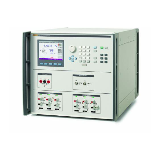
Three Phase Power Calibrator
Brand:
Fluke
| Category:
Test Equipment
| Size: 1.56 MB
Table of Contents
Table of Contents
3
Introduction
13
Contact Fluke Calibration
13
Safety Information
14
Symbols
16
Protective Earth (Grounding)
16
Features
17
Specifications
17
Input Power
17
Dimensions
17
Environment
18
Safety
18
Emc
18
General Electrical
18
Electrical Specifications
18
Temperature Coefficient
18
Voltage
18
Voltage Channel Maximum Capacitive Loading for Output Stability
18
Voltage Range Limits and Burden
19
Voltage Sine Amplitude
19
Voltage DC
20
Voltage Distortion
20
Current
20
Current Range Limits and Compliance
20
Current Sine Amplitude
21
Current DC
21
Current Distortion
21
Current Output Isolation (High or Low Terminal)
22
Voltage from the Current Terminals (DC and Sine Wave Only)
22
Range Limits and Impedances
22
Voltage from Current Terminals
22
Voltage from Current Terminals, Distortion
22
Phase and Power Factor (Sine Wave Outputs)
22
Current to Voltage Phase
22
Voltage to Voltage Phase
23
Power
23
Sinusoidal Power Specification at 40 Hz to 70 Hz, Power Factor 1.0 (%)
23
Sinusoidal Power Specification at 40 Hz to 70 Hz, Power Factor 0.8 (%)
23
Sinusoidal Power Specification at 40 Hz to 70 Hz, Power Factor 0.5 (%)
24
DC Power Specification (%)
24
Multimeter
24
IN2 Input
24
Energy (6003A/E Energy Option)
24
Pulse Inputs (IN1)
24
Energy Pulse Output
24
Energy
24
Test Duration
24
Power Quality (6003A/PQ Power Quality Option)
25
Voltage and Current Sinusoidal and Rectangular Modulation Flicker Specification
25
Harmonics and Interharmonic
25
Dip/Swell
26
Installation
27
Introduction
27
Unpack and Inspection
27
Reship the Instrument
27
Placement
28
Cooling Considerations
28
Line Voltage
28
Line Voltage Fuse
28
Connect to Line Power
29
Preparation for Operation
29
Inspect Package Contents, Installation Location
29
Installation Power and Location
30
Optional 90 a High Current Adapter
30
Power-On
31
Warmup
31
Features and Basic Operation
33
Introduction
33
Front-Panel Features
33
The Display
39
Rear Panel
41
Basic Operation
42
Select a Function
42
Setting the Value of the Output Signal
43
Edit Mode
43
Entry of the Value with the Numeric Keyboard
44
Entry of the Value with the Cursor Buttons
44
Entry of the Value with the Rotary Knob
45
Connection/Disconnection of Output Terminals
45
Control Sequence When the Output Voltage Is >100 V Is Selected
46
Multimeter
46
Front-Panel Operation
47
Introduction
47
Power up
47
Warmup
47
Set the Language on the Display
48
Function Selection
48
Setup Menu (Main Menu)
49
General Menu
50
Interface Menu
51
Calibrator Menu
51
Meter Menu
55
Calibration Menu
56
Activate the Output Terminals
56
Control Sequence When Output Voltage >100 V
57
Set the Output
58
Edit Mode
58
Enter a Value with the Numeric Keypad
58
Enter a Value with the Cursor Buttons
59
Enter a Value with the Rotary Knob
59
Generating Electric Power
59
Control in the Power Mode
60
Power Factor Polarity (Lead/Lag Softkey)
61
Power Units (Units Softkey)
61
Power Modes (Mode Softkey)
62
Setting the Power in Modes Pdc Basic and Pac Basic
63
Set the Power in Pdc High I and Pac High I Modes
65
Set the Power in Pdc Extended and Pac Extended Modes
65
Set the Amplitude of Voltage or Current
66
Set the Phase (AC Power Only)
67
Set the Frequency (AC Power Only)
68
Power Quality Modes (Available with 6003A/PQ Power Quality Option Only)
68
Set the Power in P Harmonic Mode
68
Set the Amplitude of Voltage or Current
69
Set the Phase
69
Set the Amplitude and Phase of Harmonic Components
69
Set the Modulation
70
Set the Power in P Interharmonic Mode
71
Set the Amplitude (RMS Value) of Voltage (Current)
71
Set the Phase
71
Set the Amplitude (RMS Value) of the Interharmonic Component
72
Set the Power in P Dip/Swell Mode
72
Set the Amplitude (RMS Value) of Voltage or Current
73
Set the Phase
73
Set the Amplitude (RMS Value) of Dip/Swell
74
Set Dip/Swell Time Periods
74
Generate Electric Energy (Available with 6003A/E Energy Option Installed)
74
Energy Pulse Output
74
Control in the Energy Mode
75
Power Factor Polarity (Lead/Lag Softkey)
76
Power Units (Units Softkey)
76
Methods of Energy Counting (Control)
77
Packet (Time Counting)
77
Counter (Pulse Counting)
77
Timer
77
Free Run (Frequency Measuring)
77
Energy Modes (Mode Softkey)
78
Set the Energy in Modes Edc Basic and Eac Basic
78
Set the Voltage
78
Set the Current
79
Set the Power Factor (AC Power Only)
79
Set the Frequency (AC Energy Only)
79
Set the Meter Constant
79
Set the Test and Warm-Up Periods
79
Set the Power in Modes Edc High I and Eac High I
80
Generate Voltage
80
Control in the Voltage Mode
80
Overload the Output Terminals
80
Set the Voltage in Modes VDC Basic and Vac Basic
80
Set the Voltage
80
Set the Frequency (AC Voltage Only)
81
Generate Current
81
Control in the Current Mode
81
Overload the Output Terminals
82
Current Modes (Mode Softkey)
82
Set the Current in Modes IDC Basic and Iac Basic
82
Set the Current in Modes IDC High I and Iac High I
83
Use the Multimeter
83
Product Use Tips
84
Use the Isolated Current Outputs
84
Safe Working Practices
86
How to Connect the Product to the UUT
86
How to Disconnect the Product from the UUT
86
Use the Product to Power Energy Meters
87
Verification, Calibration Adjustment, and Maintenance
89
Introduction
89
Required Equipment
89
Verification Performance Tests
91
Basic Steps of the Performance Verification Test
91
Connections and Procedure Sequences
91
VDC Amplitude Verification
92
Frequency Verification
92
Modulation Mode Voltage Amplitude Verification (0 % Modulation)
93
Voltage Modulation Mode Depth Verification
93
DC Current Amplitude Verification
94
AC Current Amplitude Verification
95
Voltage from the Current Terminals Amplitude Verification
96
Modulation Mode Current Amplitude Verification (0 % Modulation)
97
Current Modulation Mode Depth Verification
97
VAC Amplitude Verification
98
Power Amplitude Verification
99
Voltage Current Phase Verification
100
Current Voltage Phase Verification
100
Harmonic Mode Amplitude Verification
101
Interharmonic Mode Amplitude Verification
102
Harmonic Mode Voltage Phase Verification
102
Harmonic Mode Current Phase Verification
102
Multimeter Voltage Verification
103
Multimeter Frequency Verification
103
Multimeter Current Verification
104
Calibration Adjustment Principles
105
Access to the Calibration Adjustment Procedure
106
Select the Calibration Adjustment Type
107
Termination of the Calibration Adjustment Process
108
Calibration Points
109
Complete Calibration Adjustment Procedure
109
Enter the Calibration Menu
109
AC Voltage Ranges Calibration Adjustment
110
AC Current Ranges Calibration Adjustment
111
DC Voltage Ranges Calibration Adjustment
113
DC Current Ranges Calibration Adjustment
114
AC Voltage Modulation Ranges Calibration Adjustment (P Harmonic, P Interharmonic Modes)
116
AC Current Modulation Ranges Calibration Adjustment (P Harmonic, P Interharmonic Modes)
117
DC Voltage from the Current Outputs Calibration Adjustment
118
Meter Calibration Adjustment
118
10 V DC Voltage Range Calibration Adjustment
119
20 Ma DC Current Range Calibration Adjustment
119
10 Khz Frequency Range Calibration Adjustment
120
Maintenance
121
Regular Maintenance
122
Clean the Product
122
Fuse Replacement
122
In Case of Failure
124
User-Replaceable Parts
124
Error Messages
125
Introduction
125
Advertisement
Fluke 6003A Manual (56 pages)
Brand:
Fluke
| Category:
Test Equipment
| Size: 5.03 MB
Table of Contents
Table of Contents
2
Electrical Calibration
4
DC/LF Electrical Calibrators
7
Specialty Calibrators
8
Oscilloscope Calibrators
9
Precision Multimeters
9
Electrical Standards
10
RF References
12
Temperature Calibration
13
Standard Platinum Resistance Thermometers
20
Fixed-Point Cells
20
Cell Maintenance Apparatus
21
Thermometer Readouts
22
Reference Prts
23
Thermocouples
23
Thermistors
23
Compact Calibration Baths
24
Standard Calibration Baths
24
Special Application Baths
25
Bath Controllers
25
Metrology Wells
25
Field Metrology Wells
25
Dual-Block Dry-Well
26
Field Dry-Well Calibrators
26
Micro-Baths
26
Portable Calbration Baths
26
Handheld Calibrators
26
Infrared Calibrators
27
Zero-Point Dry-Well
27
Surface Probe Calibrator
27
Thermocouple Furnaces
27
Humidity Calibration
28
Humidity Calibrators
29
Pressure Calibration
30
Gas Pressure Controllers/Calibrators
34
Series Piston Gauges
34
High Pressure Controllers/Calibrators
35
Reference Pressure Indicators
35
2400 Series Piston Gauges
36
Specialty Piston Gauges
37
Manual Pressure Generation and Control
37
Industrial Deadweight Testers
38
Pressure Comparators
38
Pressure Calibrators
39
Air Data Calibration
40
Pressure Calibration Systems
40
Gas Flow Calibration
41
Gas Flow Standards
42
Calibration Software
43
Electrical and RF Calibration Software
45
Calibration Asset Management Software
45
Software Support Programs
45
Temperature Calibration Software
46
Pressure/Flow Calibration Software
47
Data Acquisition
48
2638A Hydra Series III Data Acquisition System
49
Fluke DAQ 6.0 Application Software
49
Service Programs
52
Training
53
Advertisement
Related Products
Fluke 6055
Fluke 6061A
Fluke 6200
Fluke 6270A
Fluke 6100B
Fluke 6109A
Fluke 686
Fluke 6135A/PMU
Fluke 6135A/PMUCAL
Fluke 6200-2
Fluke Categories
Measuring Instruments
Test Equipment
Multimeter
Thermometer
Laboratory Equipment
More Fluke Manuals
Login
Sign In
OR
Sign in with Facebook
Sign in with Google
Upload manual
Upload from disk
Upload from URL