Sign In
Upload
Manuals
Brands
FEC Manuals
Servo Drives
AFC3000
FEC AFC3000 Manuals
Manuals and User Guides for FEC AFC3000. We have
3
FEC AFC3000 manuals available for free PDF download: Hardware Operation Manual, Manual
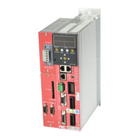
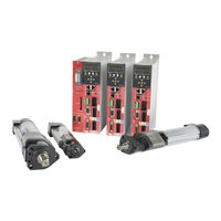
FEC AFC3000 Hardware Operation Manual (294 pages)
Nutrunner System
Brand:
FEC
| Category:
Servo Drives
| Size: 13.75 MB
Table of Contents
Table of Contents
12
Chapter 1: Outline
18
About this Operation Manual
19
Features
20
Functions
22
Safety Precautions
24
Chapter 2: Specifications
26
Specifications
26
AFC3000 System Usage Environment
27
Nutrunner Performance
28
Unit Specifications
28
Duty Cycle Calculation
30
Unit Identification
30
MFC Unit Type
30
Fieldbus Specifications
31
Chapter 3: System Description
34
System Structure
35
Single System Diagrams
36
Multi System Diagrams
38
Controller Description
40
Front Panel Switches and Connectors
40
Controller Front Panel LED
42
Controller Top & Bottom Panel Switches and Connectors
43
Controller Side Panel Connector
44
Front Display Unit
45
Expansion Unit 1
46
Tool Unit
47
Chapter 4: Installation & Wiring
64
Unit Outline and Mounting Dimensions
66
Control Panel Installation Requirements
70
Control Panel Layout
71
Tool Dimensions
72
Straight Type
72
Offset Type
77
Spindle Assemblies
79
Mounting Plate Design Requirements
83
Locating Procedure for Fixtured Multi-Spindle Powerhead
83
Unit Cable Connections
84
Input Power Source Connections
85
Circuit Protection
87
Tool Wiring and Installation
88
Tool Installation Procedures
88
Tool Cable Wiring
89
Cable Installation Guidelines
90
Considerations for Cable Trolleys
91
Considerations for Flexible Cable Track
91
Considerations for Cable Trays & Ladders
91
Connection of External Control Signals
92
PLC IO Signal (Single System)
92
PLC IO Signal (Multi System:master)
93
PLC IO Signal (Multi System:master OUTDATA Signal)
94
PLC IO Signal (Multi System:slave)
95
I/O Hardware Specifications and Recommended Connection Circuit
96
Description of I/O Signals
97
Fastening Timing Chart
102
External Monitoring Interface
104
Output Signal Specifications
104
How to Calibrate the External Monitoring Device
105
Output Circuit
105
RS-232C Interface
106
RS-232C Communication Specifications
106
RS-232C Fastening Result Output
108
RS-232C Fastening Result Output Data Item List (Single System)
111
RS-232C Fastening Result Output (Multi System)
112
ETHERNET Interface
120
TCP/IP Setup Procedures (Windows)
121
External Emergency Stop Interface
126
Communication between Spindles Interface
127
Setting of SW2 Switch on the Bottom Panel
130
Chapter 5: Expansion Units
132
Expansion Units
133
List of External Control Interfaces
133
Expansion I/O - 24VDC Discrete I
134
Description of Hardware
134
I/O Signal Specifications
135
I/O Signal Descriprions
139
PLC Output Layout
142
Description of Output Signals
145
I/O Hardware Specifications and Recommended Connection Circuit
150
Compact Flash
154
Using the (CF) Memory Card
155
Data Storage File Format
156
Formatting the Memory Card
159
Expansion RS232C Interface
160
ID Data Input Setting
161
Chapter 6 : Operational Tests
165
Power Activation・Operational Test
165
Before Powering
165
Items to be Checked When the Power Is Turned
166
Initial Data Setting
167
Chapter 7: Fastening Instructions
168
Fastening Settings Outline
169
Fastening Methods
170
Torque Control Method (Angle Monitoring)
170
Fastening Option [Data
184
Operation after Fastening [Data
189
Offset Check Function
191
Torque / Angle Judgment
193
Torque Rate Check
199
Differential Angle Check
202
Torque Inhibit Check
203
Breakaway Torque Check
203
Current Value Warnings
204
Chapter 8: System Operation
208
Controller Display Device
209
RUN/BYPASS Switch
212
RUN State
213
RUN State Mode Selection
214
REAL TIME Display Mode (Real Time Mode)
215
BYPASS State
224
BYPASS State Mode Selection
225
System Mode Change over - Multi / Single System
229
Multi System → Single System
229
Single System → Multi System
230
Parameter Copy / Erase the Fastening Results History
231
Parameter Structure
234
System Parameter
244
Fastening Parameter (Fastening Setting)
246
Fastening Parameter (Torque)
249
Chapter 9: Maintenance & Inspection
260
Inspection Items
261
Tools (Motors)
261
Cables
261
Spindle Assembly
261
Controller (MFC)
262
Transmission Disassembly and Inspection
262
Basic Operational Tests
264
Torque Transducer
264
Resolver
265
Motor
265
Replacement
266
MFC Unit
266
Tool
267
Chapter 10: Troubleshooting
268
Abnormal Condition Display
269
A.01]: Torque Transducer Errors
270
A.03]: Preamplifier Errors
273
A.04]: System Memory Errors
274
A.05]: Servo Amplifier Reply Errors
276
A.06]: Servo Amplifier Type Errors
277
A.08]: Servo Amplifier Errors
278
A.09]: Parameter Errors
282
A.10]: Multi Signal Errors
283
Ethernet Communication
288
RTC (Real Time Clock)
293
Advertisement
FEC AFC3000 Manual (41 pages)
MFC-EN Ethernet-I/P Fieldbus Expansion Unit
Brand:
FEC
| Category:
Power Tool
| Size: 2.81 MB
FEC AFC3000 Manual (36 pages)
MFC-DN Devicenet Fieldbus expansion Unit
Brand:
FEC
| Category:
Industrial Electrical
| Size: 1.55 MB
Advertisement
Advertisement
Related Products
FEC AFC1500
FEC AerPOS AP-3617
FEC AM-1008W
FEC AM-1022 Series
FEC AM-1022C3
FEC AM-1022C5
FEC AM-1022K5
FEC AerTablet
FEC AT-1450
FEC AM-1017
FEC Categories
Touch terminals
Monitor
Touch Panel
Controller
Power Tool
More FEC Manuals
Login
Sign In
OR
Sign in with Facebook
Sign in with Google
Upload manual
Upload from disk
Upload from URL