Table of Contents
Advertisement
Quick Links
Advertisement
Table of Contents

Related Manuals for FEC AFC3000


Summary of Contents for FEC AFC3000
- Page 1 AFC3000E-HW-1...
- Page 2 THE EQUIPMENT! Any questions regarding the contents of this document or any related matter should be directed to FEC INC. at (586) 580-2622, faxed to (586) 580-2620 or emailed to support@fec-usa.com. The information set forth in the following document is the property of FEC INC.
- Page 3 Introduction Thank you for purchasing the AFC3000 Nutrunner System. This instruction manual describes the procedures for installation, wiring, handling and actions to be taken in case of any failure. This instruction manual shall be delivered to the end user who operates the equipment.
- Page 4 To maintain this declaration, the product must not be put into service until the end-machinery has been declared in conformity with the provisions of the Directives. Product : Electric Servo Nutrunner Model No. : AFC3000 Manufacturer : DAI-ICHI DENTSU LTD. Directives : Machinery Directive 2006/42/EC...
- Page 5 Physical damage (example - damage caused by dropping, cut cables, etc.) Field Service required on a Warranty Part - FEC warranty covers the parts and labor only onsite at FEC. Extended warranties are available as an addition to the standard warranty period outlined above -...
- Page 6 Safety Precautions Read all instructions before operating the equipment in order to use this equipment safely and correctly. Prior to use, read this instruction manual carefully and fully understand the equipments functions, safety precautions and instructions. Safety precautions in this manual are marked with two symbols [Warning] and [Caution].
- Page 7 Safety Precautions Warning Transportation / Storage Please do not touch the tool to the tool during operation. Please make sure that the part of the body does not touch the moving parts of the tool. There is a risk of injury. Do not remove the motors and gear cases of tools while power is applied..
- Page 8 Safety Precautions Caution Transportation / Storage Transport the equipment properly according to its weight. Failure to observe this instruction may cause injury and malfunction. The conditions when transporting the equipment by ship is as below. ◆ Ambient temperature: -5°C~+55°C (Avoid freezing) ◆...
- Page 9 Safety Precautions Caution Installation / Wiring Install all tools firmly where they can bear the maximum torque during operation. Failure to observe this instruction may cause injury and malfunction. Install the Controller (MFC) Unit firmly inside the control panel using the specified screws. Failure to observe this instruction may cause malfunction.
- Page 10 Safety Precautions Caution Operation / Adjustment Never operate the equipment with wet hands. Failure to observe this instruction may cause electric shock. Keep fingers away from the Controller (MFC) Unit radiating fin and tool motors while the equipment is turned ON or for a while after the equipment is turned OFF. These parts may become very hot.
- Page 11 Manual Numbering Convention AFC3000E -HW-1 DSP1500 = Servo Press DSP1500 = Servo Press Version Number AFC1500 = Nutrunner AFC3000 = Nutrunner (Major Revision Level) FUSION = DC Hand Tool Tool FUSION = DC Hand E = English Version S = Spanish Version...
-
Page 12: Table Of Contents
1-3 Functions ......................1-5 1-4 Safety Precautions ....................1-7 Chapter 2: Specifications 2-1 Specifications ....................... 2-2 2-1-1 AFC3000 System Usage Environment ............2-2 2-1-2 Nutrunner Performance ................. 2-3 2-1-3 Unit Specifications ..................2-3 2-1-4 Duty Cycle Calculation .................. 2-5 2-2 Unit Identification ....................2-5 2-2-1 MFC Unit Type .................... - Page 13 Table of Contents 4-2-3 Spindle Assemblies ..................4-16 4-2-4 Mounting Plate Design Requirements............4-20 4-2-5 Locating Procedure for Fixtured Multi-Spindle Powerhead ......4-20 4-3 Unit Cable Connections ..................4-21 4-4 Input Power Source Connections ............... 4-22 4-4-1 Circuit Protection ..................4-24 4-5 Tool Wiring and Installation .................
- Page 14 Table of Contents Chapter 5: Expansion Units 5-1 Expansion Units ....................5-2 5-2 List of External Control Interfaces ................ 5-2 5-3 Expansion I/O – 24VDC Discrete I/O ..............5-3 5-3-1 Description of Hardware ................5-3 5-3-2 I/O Signal Specifications ................5-4 5-3-3 I/O Signal Descriprions ..................
- Page 15 Table of Contents Chapter 8: System Operation 8-1 Controller Display Device ..................8-2 8-2 RUN/BYPASS Switch ................... 8-5 8-3 RUN State......................8-6 8-3-1 RUN State Mode Selection ................8-7 8-3-2 REAL TIME Display Mode (Real Time Mode) ..........8-8 8-3-3 RUN Mode Display (Fastening Result Display Mode) ......... 8-10 8-3-4 RUN Mode Display (Fastening Parameter Display Mode) ......
- Page 16 Table of Contents Chapter 10: Troubleshooting 10-1 Abnormal Condition Display ……………………………………………………… . 10-2 10-2 [A.01]: Torque Transducer Errors …………………........... 10-3 10-3 [A.03]: Preamplifier Errors …………………………………………………………. 10-6 10-4 [A.04]: System Memory Errors ……………………………………………………. 10-7 10-5 [A.05]: Servo Amplifier Reply Errors ………………………………………… ..10-9 ……………………………………………10-10 10-6 [A.06]: Servo Amplifier Type Errors 10-7 [A.08]: Servo Amplifier Errors ……………………………………………………...
-
Page 18: Chapter 1: Outline
C h a p t e r 1 O u t l i n e Chapter 1: Outline PAGE 1-1... -
Page 19: About This Operation Manual
Maintenance and Inspection Guide for preventive maintenance. Descriptions of fastening rejects, abnormal operation Chapter 10 Troubleshooting faults and corrective actions. Contents of AFC3000 User Console are not included in this operation manual. Please refer the related manual. Related Manual AFC3000 System User Console Operation Manual... -
Page 20: Features
C h a p t e r 1 O u t l i n e 1-2 Features The AFC3000 System is our newest fastening system developed with the goal of making the AFC1500 Nutrunner System simpler and more flexible. The Multi unit functions are incorporated in the conventional Axis (Spindle) Controller, eliminating the need for the extra controller. - Page 21 The MFC Unit comes standard with a dedicated ethernet port to connect to a computer running the AFC3000 User Console Software package. Additionally, a dedicated high speed communication line between units is used making communication 250 times faster than previous system (AFC1500).
-
Page 22: Functions
1-3 Functions (1) Fastening functions The AFC3000 is user programmable to select from two different fastening methods, referred to as the Torque Control and the Angle Control methods. These methods can be selected for either clockwise (CW) or counter-clockwise (CCW) operation. - Page 23 C h a p t e r 1 O u t l i n e (6) Fastening Torque Curve Display Function The torque curve of the fastening operation can be displayed and saved using the AFC3000 software. The curve from 1980deg before the end of fastening or the curve from the start of fastening to 40 seconds from the start can be displayed by the dedicated software.
-
Page 24: Safety Precautions
Handling and Shipping • It is critical that AFC3000 System components are properly handled and shipped in order to maintain the system’s integrity. Adhere to the following requirements for shipping and handling: Loose AFC3000 MFC Units must be individually packaged and shipped in anti-static containers or wrap to prevent damage from electrostatic discharge. -
Page 26: Chapter 2: Specifications
C h a p t e r 2 S p e c i f i c a t i o n s Chapter 2: Specifications PAGE 2-1... -
Page 27: Afc3000 System Usage Environment
C h a p t e r 2 S p e c i f i c a t i o n s 2-1 Specification 2-1-1 AFC3000 System usage environment Voltage 3-phase 200 to 230V AC ±10% Drive Power Source Frequency 6 0Hz /... -
Page 28: Nutrunner Performance
Switches Axis setting switch: Maximum of 32 spindles can be set (1 spdl. to 32 spdl.) Internal setting switch: 8 bits, for setting by FEC (Unit bottom panel) MULTI LED, STATUS LED, JUDGE LED, COM. LED, BYPASS LED CONTROL POWER LED, Ethernet LED... - Page 29 C h a p t e r 2 S p e c i f i c a t i o n s MFC-S120 Controller Model MFC-S024 MFC-S060 Time display: Year ・ M onth ・ D ay ・ H our ・ M inute ・...
-
Page 30: Duty Cycle Calculation
60%. (Additional abnormals may also be caused by high duty due to the higher current and heat generated when the motor is ‘overworked’. (Make sure the motor surface temperature does not exceed 70° C (158° F) (Outer Motor Case)). Contact FEC regarding a specified cycle time more than 60% Duty. 2-2 Unit Identification... -
Page 31: Fieldbus Specifications
C h a p t e r 2 S p e c i f i c a t i o n s ● Anybus-CompactCom module unit list Type Name Description Part No. For Expansion Unit 1 CC-Link-V2 AB6211-B CC-Link V2 Interface For Expansion Unit 1 DeviceNet AB6201-B... - Page 32 C h a p t e r 2 S p e c i f i c a t i o n s 2-2-3 Tool Type CFT - 201 RS1 – S x ① ② ③ ④ ⑤ ①Max. Torque ②Motor Capacity ③Tool Form ④...
- Page 33 C h a p t e r 2 S p e c i f i c a t i o n s ● Standard Spindle Assemblies Spindle Assemblies are used to take up the travel of a threaded fastener as the fastener is rundown (so the fastener does not run out of the socket or bit) This allows the tool to be advanced to the fastener while the spindle assembly is compressed by the allowable stroke that is built in.
-
Page 34: Chapter 3: System Description
Chapter 3 System Description Chapter 3: System Description PAGE 3-1... -
Page 35: System Structure
Chapter 3 System Description 3-1 System Structure The AFC3000 Nutrunner System has two system structures. Either of the two system structure types (single system and multi system) can be selected and used with a single Unit. The system type can be changed from the display on the front panel of the Unit. For the changing method, please refer to the “System Operation”... -
Page 36: Single System Diagrams
Chapter 3 System Description 3-1-1 Single System Diagrams Unit Setting MASTER Spindle No. 1 SLAVE Spindle No. 2 Unit Front Panel SW1: No. 8 Communication axis setting System Parameter D-No. SYS-003 System Indication Single Single Each of the controllers require its own set of I/O for (PLC) control (Single spindle control). This structure is referred to as a “Single System”. - Page 37 ・ ・ ・ ・ Please note that multiple MASTER Units cannot be accessed from a single PC if a hub is not provided. ・ ・ ・ ・ To access multiple MASTER Units from a single PC, multiple AFC3000 C a u t i o n User Consoles must be started up.
-
Page 38: Multi System Diagrams
Chapter 3 System Description 3-1-2 Multi System Diagrams A Controller setup as a Master, will control the I/O of any slave controllers connected to it (via the AXIS IN / OUT connection points) This configuration is referred to as a “Multi System”. Unit Setting MASTER Spdl. - Page 39 Chapter 3 System Description Expansion I/O and Fieldbus can be added to a Multi spindle system. Additionally, Expansion RS232C and compact flash (CF) are availabale as an option. Parameter presets and Fastening results can be saved on Compact Flash using the CF expansion unit. The communication between the Controller and PC can be connected with generic (LAN) cables.
-
Page 40: Controller Description
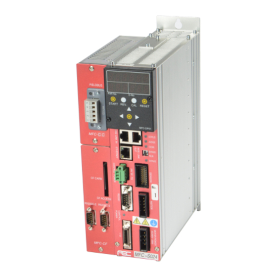
Chapter 3 System Description 3-2 Controller Description Display Unit (MFC-DP01) 3-2-1 Front Panel Switches and Connectors MFC-S024・ ・ ・ ・ MFC-S060 Plug in connector on the back side of the display unit Special Function Display unit SW1Switch Installation Connector AXIS No. Address Switch AXIS Link Connector RUN/BYPASS Switch... - Page 41 O peration Mode RUN/BYPASS Switch BYPASS S pinlde BYPASS Mode : ETHERNET Connector for Communication port for AFC3000 user console software PC communication Control Power Connector Control power connector (DC 24V) RS232C Connector Fastening data output port Sensor Connector Motor cable connectors...
-
Page 42: Controller Front Panel Led
REJECT (outside of acceptable limits) (this spindle) COM. LED Orange: PC Communication in process (AFC3000 User Console Software) BYPASS LED Light off : R UN (Operation) Mode Orange : B YPASS (BYPASS) Mode Red : M otor power off (3 phase AC) CONTROL POWER LED Green :... -
Page 43: Controller Top & Bottom Panel Switches And Connectors
Chapter 3 System Description 3-2-3 Controller Top & Bottom Panel Switches and Connectors Figure below is for unit type : M FC - S 024 and MFC - S 060 Top View Output connector for external monitoring External regeneration resistor connector Bottom View External emergency Bottom panel... -
Page 44: Controller Side Panel Connector
Chapter 3 System Description 3-2-4 Controller Side Panel Connectors Fieldbus expansion I/O connector CFcard / RS232C expansion connector ● Unit Side Panel Connector List Description Item Fieldbus expansion I/O Connection for expansion unit 1 connector CFCard / RS232C Connection for expansion unit 2 expansion connector PAGE 3-11... -
Page 45: Front Display Unit
Programming of parameters can be accomplished using the programming keys if access to the AFC3000 User Console Programming software is not available. ・ ・ ・ ・ D isplay unit must be installed firmly on the MFC unit by tightening attached screws(2 locations) shown on the figure below. -
Page 46: Expansion Unit 1
CF card slot Insert a COMPACT FLASH card in this slot CF ACCESS LED Display LED for CF card mode RS232C-2: Data Input Connector (ID Data) Expansion RS232 connectors RS232C-3: Output Fastening Results Data (Programmable output format from AFC3000 Software) PAGE 3-13... -
Page 47: Tool Unit
Chapter 3 System Description 3-2-7 Tool Unit Resolver Provides feedback for speed regulation to Servo Motor. Provides angular rotation monitoring capability to fastening operation. High Speed Motor Totally enclosed DC permanent magnet motor. RS1, RS2 & RS3 for torque ranges up to 200nm. ... - Page 48 Chapter 3 System Description 3-2-8 Cable Specification ● Single System Wiring Diagram AFC3000 User MASTER Spdl (No. 1) Console Single Control Host PC/Server Software Axis Link terminator SLAVE Spdl (No. 2) Single Control Maximum 32-Spdl configuration Axis Link terminator Control Power...
- Page 49 Chapter 3 System Description ● Multi System Wiring Diagram AFC3000 User Console Host PC/Server Software (Barcode) Serial Printer MASTER Spdl (No. 1) Multi Control Axis Link terminator SLAVE Spdl (No. 2) Multi Control Maximum 32-Spdl configuration Axis Link terminator Control Power...
- Page 50 Chapter 3 System Description ● List of System Wiring Diagram Cables (Color Code matches diagram on previous pages) Item Standard length Part # Remarks Standard Tool Cable 5, 7.5, 10, 12.5, 15, FEB-1630-Mx Replace “x” with length (for MFC-S024 / 60) 20, 25, 30 meter Extension Tool Cable 3, 5, 7.5, 10, 12.5,...
- Page 51 Chapter 3 System Description ■MFC- - - - *024,*060 Power Cables Part # : FEB-1260 10 Feet Long (Was FEB-1631 – parts are interchangeable) ●Minimum bending radius : 1 20mm ●Cable Drawing Controller Side R, S, T: 3 Phase AC Power E: Earth Ground ●Connector Model Manf.
- Page 52 Chapter 3 System Description ■MFC- - - - S120 Power Cables (Part # : F EB-1607) 10 Feet Long (For RM5 Motor) (FEB-1607A for RM4 Motor – uses (4) conductor cable only and connects to either “A” or “B” side of connector) ●Minimum bending radius :...
- Page 53 Chapter 3 System Description ●Tool Cable (Motor / Resolver / Preamplifier) Length Unit Type Cable Type ・ ・ ・ ・ M otor Wire Thickness ・ ・ ・ ・ C able Length MFC-S024 / MFC-S060 Combined Type* ・ 1 .00mm ・ M ax. 30m MFC-S120 Separated Type** ・...
- Page 54 Chapter 3 System Description ●Connector Model (Motor) Manf. Model No. Type 1-178288-5 Receptacle ・ H ousing Receptacle Contact (Pin) 1-175218-2 (Crimp type) ●Connector Size (Controller, Unit : m m) ● Connector Model (Resolver & Preamplifier) Manf. Model No. Type Connector J21DF-20V-KX-L Receptacle Contact (Pin) SJ2F-002GF-P1.0...
- Page 55 Chapter 3 System Description ● Extension Tool Cable (Motor / Preamplifier / Resolver) Offered in two types of cable: Standard Flex (Same cable as Main Cable) and High Flex. Standard Flex is for normal flexing inside of cable tray, track and light duty shifting as long as minimum bend radius is maintained.
- Page 56 ■ Tool Cable Adapter for MFC-S120 (NFT Type RM4 Motors) FEC Part# FEB-1648 This adapter is used to adapt AFC1500 cables to AFC3000 MFC controller. It plugs into the “T/D RESOLVER” connector on the front of the controller and provides a means to connect AFC1500 cables (2) to the MFC controller.
- Page 57 Chapter 3 System Description ■Control Power Connector (Common for all units) 24VDC control power must be supplied for each MFC Controller. Common 20-22AWG wire can be used to wire the supplied teriminal connector on the front of the controller. (Wire color shown as reference only – wire to local codes) 20-22AWG Green Green...
- Page 58 Model No. Type 20-22AWG Connector Phoenix Contact MC 1,5/2-STF-3,81 Connector Case Phoenix Contact KGG-MC 1.5/2 (not required) *Note: Connector available from FEC or other sources – wiring is responsibility of user ●Connector Size (Unit side, Unit : m m) PAGE 3-25...
- Page 59 Chapter 3 System Description ■ PC Communication Ethernet Cable ( C rossover ) ( P art # : F EB-1331-3 ) (The Crossover cable is required direct from a PC to the Axis controller – Note: Newer PC’s have auto-detect Ethernet hardware and a straight cable will work in place of a crossover cable) ●Cable Drawing Shield Frame...
- Page 60 Chapter 3 System Description ■ Axis Link Cable For communication between spindles ( B etween units ) ( P art # : F EB-1635 ) 1 ft. ●Cable Drawing RJ-45 Connector RJ-45 Connector Shield Frame Frame ■ Electrical Terminator for communication between spindle ( F EC Part # : F EB-1642 ) ●Cable Drawing (Ref.
- Page 61 Chapter 3 System Description ■ I/O Cable (For standard unit) ( P art # : F EB-1634 ) 9.8 Feet Long * This cable can only be used on the standard MFC unit front panel (I/O connector) ●Drawing for outside view of cables (Ref.
- Page 62 Chapter 3 System Description ■ I/O Cable for expansion unit ( P art # : F EB-1643) * This cable can only be used with Expansion Unit I/O (MFC-DT : 32IN / 32OUT) ● Cable Drawing (dimension units: mm) ● Connector Model No. (Unit Side) Model No.
- Page 63 Chapter 3 System Description * Example: Orange ・ Black 2 dots Wire color: Orange Black dots: 2 * I/O Expansion Connector Pin Configuration Wire Color* Details Wire Color* Details Orange ・ Black 1 Orange ・ Red 1 IN COMMON1 OUT COMMON1 IN COMMON2 OUT COMMON2 Grey ・...
-
Page 64: Chapter 4: Installation & Wiring
C h a p t e r 4 I n s t a l l a t i o n a n d W i r i n g Chapter 4: Installation and Wiring PAGE 4-1... - Page 65 6 Select an adequate PLC. PAGE 4-29 connection to the AFC3000 System I/O (24 VDC). Design (or review) PLC A PLC logic program can be written using signal PAGE 4-30~37 logic. descriptions and timing charts provided.
-
Page 66: Unit Outline And Mounting Dimensions
C h a p t e r 4 I n s t a l l a t i o n a n d W i r i n g 4-1 Unit Outline and Mounting Dimensions MFC-S024、 、 、 、 MFC-S060 Controllers Type Installation Weight... - Page 67 C h a p t e r 4 I n s t a l l a t i o n a n d W i r i n g ※Dimensions with an Expansion unit are stated below. Type Installation Weight Internal fan One bell screw hole: M4 screw u pper part...
- Page 68 C h a p t e r 4 I n s t a l l a t i o n a n d W i r i n g MFC-S120 Controller Internal Type Installation Weight Two bell screw holes: M6 screw U pper part (...
- Page 69 C h a p t e r 4 I n s t a l l a t i o n a n d W i r i n g ※Dimensions with an Expansion unit are stated below. Internal Type Installation Weight Two bell screw hole: M6 screw u pper part...
-
Page 70: Control Panel Installation Requirements
C h a p t e r 4 I n s t a l l a t i o n a n d W i r i n g 4-1-1 Control Panel Installation Requirements 100 ㎜ or larger 10 ㎜ 10 ㎜... -
Page 71: Control Panel Layout
C h a p t e r 4 I n s t a l l a t i o n a n d W i r i n g 4-1-2 Control Panel Layout ** + 40 ㎜ ** ㎜ ** ㎜ ** ㎜... -
Page 72: Tool Dimensions
Tool dimensions and mounting specifications are critical in determining the design of the mounting plate of the tool assemblies. Tools are offered with two connector (exit) options. (Note: All tool drawings may be downloaded from FEC website “Support” section) Provide adequate clearance to ensure that the tool assemblies do not come in contact with any object. - Page 73 C h a p t e r 4 I n s t a l l a t i o n a n d W i r i n g “L” Version Tool ● CFT-101RS1-SL, CFT-201RS1-SL, CFT-281RS1-SL , CFT-401RS1-SL Front mounting dimensions same as standard tool above) Max.
- Page 74 C h a p t e r 4 I n s t a l l a t i o n a n d W i r i n g Standard Tool ● CFT-801RS3-S, CFT-132RS3-S(1) “L” Version Tool ● CFT-801RS3-SL, CFT-132RS3-S(1)L Front mounting dimensions same as standard tool above) Square Max.
- Page 75 C h a p t e r 4 I n s t a l l a t i o n a n d W i r i n g Standard Tool ● CFT-202RS3-S “L” Version Tool ● CFT-202RS3-SL Front mounting dimensions same as standard tool above) Square Max.
- Page 76 C h a p t e r 4 I n s t a l l a t i o n a n d W i r i n g Standard Tool ● CFT-302RS3-S “L” Version Tool ● CFT-302RS3-SL Front mounting dimensions same as standard tool above) Square Max.
-
Page 77: Offset Type
C h a p t e r 4 I n s t a l l a t i o n a n d W i r i n g 4-2-2 Offset Type ● CFT-201RS1-O, CFT-401RS1-O Max. Max. Min. Square Length Mass Tool Type Torque... - Page 78 C h a p t e r 4 I n s t a l l a t i o n a n d W i r i n g ● CFT-132RS3-O(1) Max. Max. Min. Square Mass Tool Type Torque Drive [kgf] [Nm] [rpm]...
-
Page 79: Spindle Assemblies
C h a p t e r 4 I n s t a l l a t i o n a n d W i r i n g 4-2-3 Spindle Assemblies Standard spindle assemblies mount inline with either a Straight Type or Offset Type tool. They are used to “follow”... - Page 80 C h a p t e r 4 I n s t a l l a t i o n a n d W i r i n g Straight (Standard) ● SA-3S1-x-38-38 (x = stroke in inches: 2 std., 3 or 4 optional) Standard Stroke Female Input Male Output...
- Page 81 C h a p t e r 4 I n s t a l l a t i o n a n d W i r i n g ● SA-3S3-x-62-62 (x = stroke in inches: 2 std., 3 or 4 optional) Standard Stroke Female Input Male Output...
- Page 82 C h a p t e r 4 I n s t a l l a t i o n a n d W i r i n g Offset (Standard) ● OA-3S3-x-50-50 (x = stroke in inches: 2 std., 3 or 4 optional) Standard Stroke Female Input Male Output...
-
Page 83: Mounting Plate Design Requirements
C h a p t e r 4 I n s t a l l a t i o n a n d W i r i n g 4-2-4 Mounting Plate Design Requirements The plate to which the tools are mounted must maintain the following specifications: ... -
Page 84: Unit Cable Connections
C h a p t e r 4 I n s t a l l a t i o n a n d W i r i n g 4-3 Unit Cable Connections MFC-S024・ ・ ・ ・ MFC-S060 MFC-S120 External Monitoring Device Cable (Upper Panel) (Connects to monitor device) * Not used for fastening setting. -
Page 85: Input Power Source Connections
C h a p t e r 4 I n s t a l l a t i o n a n d W i r i n g 4-4 Input Power Source Connections Supply motor power to the AC 200-230V MOTOR POWER connector located on the lower right corner of the unit. - Page 86 C h a p t e r 4 I n s t a l l a t i o n a n d W i r i n g Supply 24VDC to the CONTROL POWER connector located on the left middle area of the unit. Cable side connector :...
-
Page 87: Circuit Protection
C h a p t e r 4 I n s t a l l a t i o n a n d W i r i n g 4-4-1 Circuit Protection ● Rated Values for Calculating Circuit Protection for 200-230VAC 3 phase MFC Type Motor Type Motor Wattage # of Spindles per KVA KVA per Spindle MFC-S024 8 Spindles... -
Page 88: Tool Wiring And Installation
C h a p t e r 4 I n s t a l l a t i o n a n d W i r i n g 4-5 Tool Wiring and Installation 4-5-1 Tool Installation Procedures Avoid mechanical contact on the TOOL Unit main body. _ Contact between tools. -
Page 89: Tool Cable Wiring
C h a p t e r 4 I n s t a l l a t i o n a n d W i r i n g 4-5-2 Tool Cable Wiring Tools are connected to the Controller using one cable (2 cables for RM5 motors). •... -
Page 90: Cable Installation Guidelines
C h a p t e r 4 I n s t a l l a t i o n a n d W i r i n g 4-5-3 Cable Installation Guidelines Improper installation of cables can reduce cable life expectancy drastically. The following guidelines should be used when installing cables. -
Page 91: Considerations For Cable Trolleys
C h a p t e r 4 I n s t a l l a t i o n a n d W i r i n g 4-5-4 Considerations for Cable Trolleys • Cables hung by festooning type systems must be secured to the individual cable trolley and positioned to avoid sharp bends and eliminate or minimize any torsion twisting. -
Page 92: Connection Of External Control Signals
C h a p t e r 4 I n s t a l l a t i o n a n d W i r i n g 4-6 Connection of External Control Signals Connector on cable side S umitomo 3M Made :... -
Page 93: Plc Io Signal (Multi System:master)
C h a p t e r 4 I n s t a l l a t i o n a n d W i r i n g 4-6-2 PLC IO Signal (Multi System: : : : Master) Signal Name IN/OUT Function U sage Instruction... -
Page 94: Plc Io Signal (Multi System:master Outdata Signal)
C h a p t e r 4 I n s t a l l a t i o n a n d W i r i n g 4-6-3 PLC IO Signal (Multi System: : : : Master OUTDATA Signal) BANK OUT DATA Signal Name... -
Page 95: Plc Io Signal (Multi System:slave)
C h a p t e r 4 I n s t a l l a t i o n a n d W i r i n g 4-6-4 PLC IO Signal (Multi System: : : : Unit set as SLAVE) Signal Name IN/OUT Function... -
Page 96: I/O Hardware Specifications And Recommended Connection Circuit
C h a p t e r 4 I n s t a l l a t i o n a n d W i r i n g 4-6-5 I/O Hardware Specifications and recommended connection circuit User side PLC Connector ユーザー側 PLC AFC3000 PLC I/F コネクタ Input Hardware Spec. 2.2KΩ 出力ハードウェア仕様... -
Page 97: Description Of I/O Signals
C h a p t e r 4 I n s t a l l a t i o n a n d W i r i n g 4-6-6 Description of I/O Signals [Input Signals] ・ ・ ・ ・ T he input signals used in the standard I/O are described in this section. - Page 98 C h a p t e r 4 I n s t a l l a t i o n a n d W i r i n g BYPASS: Spindle off signal (Normally Open) When active (on), all functions of the spindle controller are disabled and a BYPASS signal is output, making it impossible to start the spindle.
- Page 99 C h a p t e r 4 I n s t a l l a t i o n a n d W i r i n g SEQUENCE SELECT BIT 0~4: Sequence Select Bit (Binary coded) Used when set as Multi System ...
- Page 100 Output “ON” when the fastening results are available to be collected via the AXIS LINK. This signal turns “OFF” after data collection has completed and can be used to monitor that the AFC3000 software is monitoring / collecting data (when AFC3000 Software is used) PAGE 4-37...
- Page 101 C h a p t e r 4 I n s t a l l a t i o n a n d W i r i n g BYPASS: BYPASS Mode signal – Slave (Normally Open) Output “ON” when a unit is in BYPASS mode on a Slave spindle of both a single system and a multi system.
-
Page 102: Fastening Timing Chart
C h a p t e r 4 I n s t a l l a t i o n a n d W i r i n g 4-6-7 Fastening Timing Chart Basic Control Signal C ontact is “Open” from PLC side :... - Page 103 C h a p t e r 4 I n s t a l l a t i o n a n d W i r i n g 2. Fastening Parameter Selection Signal and Start Timing C ontact is “Open” from PLC side :...
-
Page 104: External Monitoring Interface
C h a p t e r 4 I n s t a l l a t i o n a n d W i r i n g 4-7 External Monitoring Interface 4-7-1 Output Signal Specifications This auxiliary connector (Located under top cover access plate) is used to output Torque, Angle, Current &... -
Page 105: How To Calibrate The External Monitoring Device
C h a p t e r 4 I n s t a l l a t i o n a n d W i r i n g 4-7-2 How to Calibrate the External Monitoring Device When pressing the CAL switch on the unit display device, the torque voltage is output to TORQUE OUT pin with the voltage potential difference of approximately ⊿3.7V (from tool ZERO level) At the same time, the torque value detected on the tool is displayed on the DATA display screen. -
Page 106: Rs-232C Interface
Setup). If certain data is only required or a user-defined smaller format, then use the RS232C port on the MFC front panel (configured as a MULTI system) OR the RS232C-3 port using the AFC3000 software to program / setup the desired output format. - Page 107 C a u t i o n C a u t i o n C a u t i o n C a u t i o n Note: This port may also be used for Controller Firmware updates (FEC use only) PAGE 4-44...
-
Page 108: Rs-232C Fastening Result Output
C h a p t e r 4 I n s t a l l a t i o n a n d W i r i n g 4-8-2 RS-232C Fastening Result Output Format (SINGLE system) Fastening result data is output from the RS232C port on the front of the MFC Unit (configured as a SINGLE system) in a fixed format when a fastening is completed. - Page 109 C h a p t e r 4 I n s t a l l a t i o n a n d W i r i n g Byte Item Final Angle Sign Differential Angle ASCII DATA Byte Sign Rate 1 Sign Rate 2...
- Page 110 C h a p t e r 4 I n s t a l l a t i o n a n d W i r i n g Spindle Judgment definition: Spindle Judgment Output Format REJECT ACCEPT ABNORMAL STOP RESET STOP BYPASS START OFF...
-
Page 111: Rs-232C Fastening Result Output Data Item List (Single System)
C h a p t e r 4 I n s t a l l a t i o n a n d W i r i n g 4-8-3 RS-232C Fastening Result Output Data Item List (Single System) Fastening data items (for the Single System) are as follows; Item Byte # Data Format... -
Page 112: Rs-232C Fastening Result Output (Multi System)
C h a p t e r 4 I n s t a l l a t i o n a n d W i r i n g 4-8-4 RS-232C Fastening Result Output (Multi System) Setup as a Multi system, the RS232C data format is programmable with the AFC3000 User Console software. Either an ASCII format or BCD format can be selected as the data output format. - Page 113 C h a p t e r 4 I n s t a l l a t i o n a n d W i r i n g Spindle data output format • Number Axis Format Fastening Output Items Data 3word 4word...
- Page 114 C h a p t e r 4 I n s t a l l a t i o n a n d W i r i n g *3: With each of the output items for which there are set values of high and low limits, the results are output in the order of: sign, result indication (including the decimal point), judgment code, and 1st Reject (failure) item.
- Page 115 C h a p t e r 4 I n s t a l l a t i o n a n d W i r i n g ・Spindle Data Output Items Axis format Number Fastening Output Items of Bytes Data 2 word 1 word...
- Page 116 C h a p t e r 4 I n s t a l l a t i o n a n d W i r i n g *1: Please refer to “Spindle Judgment” (above) regarding the details of the spindle judgment. *2: With each of the output items besides “Spdl.
- Page 117 C h a p t e r 4 I n s t a l l a t i o n a n d W i r i n g bit7 bit 6 bit 5 bit 4 bit 3 bit 2 bit 1 bit 0 ③...
- Page 118 C h a p t e r 4 I n s t a l l a t i o n a n d W i r i n g ⑤ 1st fastening Reject (Failure) Item Reject Item Output format No Reject Peak torque high limit Peak torque low limit Final torque high limit...
- Page 119 C h a p t e r 4 I n s t a l l a t i o n a n d W i r i n g ● Judgment Flag Output Examples Example 1: Final torque low limit reject, final angle low limit reject, 2nd time high limit reject (1 reject item) bit7...
-
Page 120: Ethernet Interface
C h a p t e r 4 I n s t a l l a t i o n a n d W i r i n g 4-9 ETHERNET Interface The ETHERNET interface is a dedicated TCP/IP Ethernet port to communicate with the AFC3000 User Console software installed on a PC (Windows®). -
Page 121: Tcp/Ip Setup Procedures (Windows)
C h a p t e r 4 I n s t a l l a t i o n a n d W i r i n g 4-9-1 TCP/IP Setup Procedures (Windows®) The Ethernet settings on the PC side may need to be changed in order to communicate to the controller via Ethernet. - Page 122 C h a p t e r 4 I n s t a l l a t i o n a n d W i r i n g 4. Select “Properties” in Local Area Connection Status. 5. In Local Area Connection Properties, select “Internet Protocol Version 4 (TCP/IPv4)” and then select “Properties”.
- Page 123 PC to the prior settings if you try to connect back to your PC network. 7. Register the IP address in the AFC3000 User Console. Please refer to “TCP/IP Setting Procedures (User Console)” on PAGE 3-27.
- Page 124 1. If the TCP/IP settings of the MFC controller are set to anything other than the default settings, then the new IP address will need to be registered in the AFC3000 User Console Software. The communication setting window is displayed automatically when the User Console software is started.
- Page 125 C h a p t e r 4 I n s t a l l a t i o n a n d W i r i n g 4-A. If connection with the Unit is successful, the “Connect” indication changes from “Disconnect”...
-
Page 126: External Emergency Stop Interface
C h a p t e r 4 I n s t a l l a t i o n a n d W i r i n g 4-10 External Emergency Stop Interface The External Emergency Stop Interface is able to forcedly STOP a system by inputting an emergency stop signal via the AUX connector on the bottom panel of the unit. -
Page 127: Communication Between Spindles Interface
C h a p t e r 4 I n s t a l l a t i o n a n d W i r i n g 4-11 Communication between Spindles The communication between spindles is conducted via a dedicated communication port on each MFC unit. The AXIS LINK OUT connector of one unit must be connected with the AXIS LINK IN connector of the next unit together one by one. - Page 128 C h a p t e r 4 I n s t a l l a t i o n a n d W i r i n g 4-12 Setting Spindle Number Switches 4-12-1 Setting the Spindle No. Switch Axis No.
- Page 129 C h a p t e r 4 I n s t a l l a t i o n a n d W i r i n g 4-12-2 Setting the Special Function Switch - SW1 The SW1 switches on the Unit front panel are used to set special functions related to fastening.
-
Page 130: Setting Of Sw2 Switch On The Bottom Panel
C h a p t e r 4 I n s t a l l a t i o n a n d W i r i n g 4-12-3 Setting of SW2 switch on the bottom panel O F F S i d e O F F S i d e O F F S i d e O F F S i d e... - Page 131 C h a p t e r 4 I n s t a l l a t i o n a n d W i r i n g (Blank Page) PAGE 4-68...
-
Page 132: Chapter 5: Expansion Units
Chapter 5 Expansion Unit Chapter 5: I/O Expansion Unit Page 5-1... -
Page 133: Expansion Units
5-1 Expansion Units The AFC3000 has two expansion units that are attached to the MASTER of any system configuration. Expansion Unit 1 mounts to the upper location on the left side of the Master spindle. It is dedicated for I/O expansion. -
Page 134: Expansion I/O - 24Vdc Discrete I
Chapter 5 Expansion Unit 5-3 Expansion I/O – 24VDC Discrete I/O 5-3-1 Description of the Hardware (Expansion I/O) Expansion I/O allows additional I/O signals to be used (32IN / 32OUT) vs. the connector on the front of the MFC controller. It is especially useful in MUTLIPLE Spindle systems where individual spindle output status is desired using one connection point. -
Page 135: I/O Signal Specifications
Chapter 5 Expansion Unit 5-3-2 I/O Signal Specifications (Expansion I/O) ● PLC Expansion Input Signals (Expansion I/O → MASTER Spindle) Signal Description of Function/Usage IN COMMON Common input signal (bidirectional) IN COMMON The fastening operation is stopped by setting this signal to “OFF” STOP IN NC (emergency stop signal). - Page 136 Input signal mapping is fixed (cannot be changed). Caution Use the AFC3000 User Console Software for sequence programming. Be careful of the following points when using the BYPASS No. # (1 to 10 spindle) signals. ・ If a certain Controller is to be put in the BYPASS mode, set the corresponding signal among the BYPASS No.
- Page 137 The mapping of the output signals is programmable using the “PLC Output Layout” of the AFC3000 User Console Software. A description of available output signals can be found below, later in this chapter. Output signals from the Master spindle (as a group) or individual connected spindles is available.
- Page 138 Chapter 5 Expansion Unit Bank Bank Pin No./Signal Bank Bank Pin No./Signal OUT COMMON OUT COMMON OUT COMMON OUT COMMON 1 REJECT No.9 2 ACCEPT No.9 3 ABNORMAL No.9 4 BYPASS No.9 5 REJECT No.10 6 ACCEPT No.10 7 ABNORMAL No.10 8 BYPASS No.10 9 REJECT No.11 46 10 ACCEPT No.11...
-
Page 139: I/O Signal Descriprions
“Signal Input,” the cycle count of the selected sequence No. is cleared. The sequence cycle count is set to 1 at the start of the next fastening operation. The sequence counting method is changed using the AFC3000 User Console (the factory setting is “Automatic Count Up”). CYCLE COUNT UP: Sequence Cycle Counter Increment Signal When the CYCLE COUNT UP signal is set to “ON”... - Page 140 When the ID SELECT ENABLE signal is set “ON,” it enables the function to select the sequence from the part ID data. In conjunction with this input, it also has to be setup in the AFC3000 User Console software where the “Input from ID Data,” is selected in the “RS232C Input Format/Data Input Setup”...
- Page 141 Chapter 5 Expansion Unit [Table 2 – Sequence Select Output] Sequence Sequence Sequence Sequence Sequence Selected Fastening Output 4 Output 3 Output2 Output1 Output0 Sequence No. … … … … … … … … … … Page 5-10...
-
Page 142: Plc Output Layout
MASTER controller can provide output signals for the TOTAL group of spindles as well as invidual spindle signals (up to 32 spindles) These signals are user configurable using the AFC3000 User Console software and may be programmed on any designated output bit. - Page 143 Chapter 5 Expansion Unit (Continued from previous page) Output confirmation (echo) of the Fieldbus Message Bank Select signals. Message Spindle Offset bits are active according to the input status of the Fieldbus Message Bank Select Input bits when using the Fieldbus Message Spindle message offset feature.
- Page 144 Chapter 5 Expansion Unit ●Individual Spindle Output Signals (spindle 1 to 32) Signal Description of Function/Usage Connection Output when the fastening result is a REJECT. Indicates that the spindle Reject has failed achieving the fastening limits. This output remains active until the START signal or RESET signal is input.
-
Page 145: Description Of Output Signals
Chapter 5 Expansion Unit 5-3-5 Description of Output Signals ACCEPT: Fastening ACCEPT Signal TOTAL ACCEPT: Total ACCEPT Signal REJECT: Fastening REJECT Signal TOTAL REJECT: Total REJECT Signal ABNORMAL: System Error/Abnormal Exit TOTAL ABNORMAL: Total System Error/Abnormal Exit READY: Input Enabling Signal TOTAL READY: Total Input Enabling Signal BUSY: Signal During Fastening TOTAL BUSY: Sequence-Operation-in-Progress Signal... - Page 146 Chapter 5 Expansion Unit REJECT No. # (1 to 32): REJECT Signal of Spindle 1-32 Output when the fastening result is a REJECT. Indicates that the spindle is within fastening limits. This output remains active until the START signal or RESET signal is input. BYPASS No.
- Page 147 Chapter 5 Expansion Unit REVO. LO REJ. No. # (1 to 32): Rundown Revolution Low Limit Signal of Spindle 1-32 The signal is set “ON” if the value of the rundown revolution is below the fastening parameter D-No. 503 “Rundown Revolution Low Limit.” TQ.
- Page 148 The signal is set “ON” if the value of rate 3 is below the fastening parameter D-No. 304 “Rate 3 Low Limit.” NOTE:The following output signals can be set in “PLC Output Layout” of the AFC3000 User Console Software. OUTPUT PORT (1 to 8): Output Signal Ports 1 to 8 These signals will output when the fastening sequence reaches a step that has a [PLC OUTPUT] instruction inserted.
- Page 149 Chapter 5 Expansion Unit PEAK TQ LO REJ. No. # (1 to 32): Peak Torque Low Limit Signal of Spindle 1-32 The signal is set “ON” if the value of the peak torque is below the fastening parameter D-No. 101 “Peak Torque Low Limit.”...
-
Page 150: I/O Hardware Specifications And Recommended Connection Circuit
Chapter 5 Expansion Unit 5-3-6 I/O Hardware Specifications and Recommended Connection Circuit PLC I/F Connector User Side PLC Input Hardware Specifications Input Signal** Input Signal** Output Hardware Specifications Output Signal** Output Signal** Power Source NOTE: The input / output hardware is bi-directional and accommodates both positive and negative current flow. (NPN Sinking is shown –... - Page 151 Chapter 5 Expansion Unit 5-3-7 Timing Chart ● Basic Control Signals: Master OFF: Contact is “Open” from the PLC ・ Input Signals ON: Contact is “Closed” from the PLC Fastening Operation Operation progress ・ Output Signals 100msec Page 5-20...
- Page 152 Chapter 5 Expansion Unit ●Fieldbus Message Output Timing Fastening Operation Fieldbus Message Output Output started ・ Output Signals (renewed at the end of the next operation) OFF: Contact is “Open” from the PLC ● Basic Control Signals: Slave Spindle ON: Contact is “Closed” from the PLC ・...
- Page 153 Chapter 5 Expansion Unit ● ID Data Output Timing ・ Input Signals Fastening Operation Operation progress ID Input ID Output ・ The part ID data that is input from the RS232C or the fieldbus (and is input BEFORE the start of fastening) is “married” together with the fastening data at the end of the fastening operation.
-
Page 154: Compact Flash
Chapter 5 Expansion Unit 5-4 Compact Flash Fastening results and fastening waveforms can be stored as files in a CompactFlash (CF) card in the CF expansion unit. (hereinafter, “memory card”). The stored data can be read with any PC containing a Compact Flash card reader. ・... -
Page 155: Using The (Cf) Memory Card
Chapter 5 Expansion Unit 5-4-1 Using the (CF) Memory Card 1. Turn OFF power and insert the memory card in the memory card slot (CF CARD) of Expansion Unit 2. ・ When the control power of the Unit is turned ON with the memory card installed in the slot, it takes additional time for the memory to become operable because a file storage folder is generated in the Caution... -
Page 156: Data Storage File Format
(torque vs. angle (180deg)) curve file of each spindle is stored in the “nracd” format, which is dedicated for use with the AFC3000 User Console. The fastening curve displayed on the “Wave Monitor” of the AFC3000 User Console Software can be stored in the TSV format. - Page 157 Chapter 5 Expansion Unit ● Fastening Curves (Waveforms) (Storage for Respective Spindles) Fastening Curve files are stored in the automatically-generated folder “CURVE.” Inside the “CURVE” folder, folders each with a name expressing the year and month, such as “201309,” are generated automatically, and a folder is automatically generated in the manner of “201310,”...
- Page 158 Chapter 5 Expansion Unit ● Procedure for Confirming the Storable Capacity of the Memory Card 1. Put the Unit in bypass (or do not put the controller into cycle) and then perform the following when the controller “READY” signal is “ON.” 2.
-
Page 159: Formatting The Memory Card
Chapter 5 Expansion Unit 5-4-3 Formatting the Memory Card All data stored in the memory card can be erased by operation from the display unit. The CF memory card must be formatted before use for the first time. ・ Do not extract the memory card during formatting of the memory card. The card may be damaged and become incapable of use. -
Page 160: Expansion Rs232C Interface
・ The setting of the RS232C ports, the sequence selection setting from the input ID code, and setting of the RS232C input format are performed on the MASTER Spindle from “RS232C Input Format/Data Input Setting” of the AFC3000 User Caution Console Software. -
Page 161: Id Data Input Setting
Expansion Unit 5-5-1 ID Data Input Setting With the AFC3000 System, part ID data (ID No.) can be input into the MASTER spindle using the RS232C-2 interface of Expansion Unit 2. The expansion RS232C is set as the factory setting. - Page 162 Chapter 5 Expansion Unit When the expansion RS232C is selected as the data input method and “Add STX/ETX” is selected, the ID data can be cleared when the STX signal is received via the RS232C-2 and data can be re-input by ending the input data when the ETX signal is received.
- Page 163 ID data. To set the sequence selection method, the AFC3000 User Console software must be used. With the PLC IO input signal “ID SELECT ENABLE Signal” set “ON,” the “Select by Input ID”...
- Page 164 Chapter 6 Power up and Initial Checks Chapter 6: Power Up and Initial Checks PAGE 6-1...
-
Page 165: Power Activation・Operational Test
Chapter 6 Power up and Initial Checks 6-1 Power Activation・ ・ ・ ・ Operational Test WARNING DO NOT operate the system WITHOUT all safety guards and/or devices in place and operational. Follow Lockout/Tago ut and other safety precautions when performing maintenance or connecting / disconnecting cabling, wiring, and equipment. -
Page 166: Items To Be Checked When The Power Is Turned
Chapter 6 Power up and Initial Checks 6-1-2 Items to be checked when the power is turned on When the power is turned on, check that the display unit will change. (See a figure below) RUN Mode Controller Spindle Display lights all digits for approx.. -
Page 167: Initial Data Setting
System. The system will not run until this data is correctly set-up. Programming should be performed using the FEC Inc. “AFC3000 Userconsole” software to simplify the programming operation and to provide a means of creating a back-up file of the Set-up. -
Page 168: Chapter 7: Fastening Instructions
C h a p t e r 7 F a s t e n i n g I n s t r u c t i o n s Chapter 7: Fastening Instructions PAGE 7-1... -
Page 169: Fastening Settings Outline
C h a p t e r 7 F a s t e n i n g I n s t r u c t i o n s 7-1 Fastening Settings Outline ● Fastening Method Description Referring Fastening Method page PAGE Fasten until attaining the torque value set as the standard torque... -
Page 170: Fastening Methods
C h a p t e r 7 F a s t e n i n g I n s t r u c t i o n s 7-2 Fastening Methods The AFC3000 System is user programmable to select from two different fastening methods, referred to as Torque Control and Angle Control methods. Each control method can be performed in 1 to 3 incremental steps, which will successively secure the fastener to the specified torque or angle values. - Page 171 C h a p t e r 7 F a s t e n i n g I n s t r u c t i o n s <One-step Fastening – Using 1 and 2 Torque> Torque Standard Torque Torque Snug Torque Torque...
- Page 172 C h a p t e r 7 F a s t e n i n g I n s t r u c t i o n s <Torque Control Method・ ・ ・ ・ Two-step Fastening> Two-step fastening will be used primarily for joints that have a requirement to synchronize with another spindle during the final stage of the rundown or require joint conditioning.
- Page 173 C h a p t e r 7 F a s t e n i n g I n s t r u c t i o n s <Two-step Fastening – Using 1 and 2 Torque> Torque Standard Torque Torque Snug Torque Torque...
- Page 174 C h a p t e r 7 F a s t e n i n g I n s t r u c t i o n s <Torque Control Method・ ・ ・ ・ Three-step Fastening> Three-step fastening will be used primarily for joints that have a requirement to synchronize with another spindle during the incremental stages of the rundown to crush/compress a gasket or grommet or for special joint conditioning.
- Page 175 C h a p t e r 7 F a s t e n i n g I n s t r u c t i o n s <Three-step Fastening – Using 1 and 2 Torque> Torque Standard Torque Torque Snug Torque Torque...
- Page 176 C h a p t e r 7 F a s t e n i n g I n s t r u c t i o n s <Three-step Fastening – Using 1 and 2 Angle> Torque Standard Torque Angle Angle Snug Torque...
- Page 177 C h a p t e r 7 F a s t e n i n g I n s t r u c t i o n s 7-2-2 Angle Control Method (Torque Monitoring) In Angle Control method, fastening is performed based upon attaining a desired torque value and then rotating the fastener a specified number of degrees, while monitoring the torque of the fastener and time.
- Page 178 C h a p t e r 7 F a s t e n i n g I n s t r u c t i o n s <One-step Fastening – Using 1 and 2 Torque> Torque Standard Angle Torque Snug Torque Torque...
- Page 179 C h a p t e r 7 F a s t e n i n g I n s t r u c t i o n s <Angle Control Method・ ・ ・ ・ Two-step Fastening> Two-step fastening will be used primarily for joints that have a requirement to synchronize with another spindle during the final stage of the rundown or require joint conditioning.
- Page 180 C h a p t e r 7 F a s t e n i n g I n s t r u c t i o n s <Two-step Fastening – Using 1 Torque (synchronize/stop) and 2 Torque> Torque Standard Angle Torque Snug Torque...
- Page 181 C h a p t e r 7 F a s t e n i n g I n s t r u c t i o n s <Angle Control Method・ ・ ・ ・ Three-step Fastening> Three-step fastening will be used primarily for joints that have a requirement to synchronize with another spindle during the incremental stages of the rundown to crush/compress a gasket or grommet or for special joint conditioning.
- Page 182 C h a p t e r 7 F a s t e n i n g I n s t r u c t i o n s <Three-step Fastening – Using 1 and 2 Torque (synchronize/stops)> Torque Standard Angle Torque Snug Torque Torque...
- Page 183 C h a p t e r 7 F a s t e n i n g I n s t r u c t i o n s <Three-step Fastening – Using 1 and 2 Angle (synchronize/stops)> Torque Standard Angle Angle Angle Snug Torque...
-
Page 184: Fastening Option [Data
C h a p t e r 7 F a s t e n i n g I n s t r u c t i o n s 7-2-3 Fastening Option Data No. 002 • Reverse Before Fastening Reverse the amount of D-No.501 [Reverse 2 Revolutions] at D-No.406 [Reverse 2 Speed] before fastening starts. - Page 185 C h a p t e r 7 F a s t e n i n g I n s t r u c t i o n s • Torque Hold Between Steps When Torque Hold Between Steps is enabled, torque is held at one quarter of the next step torque value until the next step is initiated.
- Page 186 C h a p t e r 7 F a s t e n i n g I n s t r u c t i o n s • Disable Angle Count below Snug Torque This selection disables the counting of the rotation angle while the torque value is below Snug Torque.
- Page 187 C h a p t e r 7 F a s t e n i n g I n s t r u c t i o n s Fastener Slip Check • This selection enables fastener slip detection during the fastening process. (Example: A fastener with a nut on opposite side starts to rotate or ‘slip’...
- Page 188 C h a p t e r 7 F a s t e n i n g I n s t r u c t i o n s Return to Freerun Speed if Torque Drops Below Ramp Down Start Torque •...
-
Page 189: Operation After Fastening [Data
C h a p t e r 7 F a s t e n i n g I n s t r u c t i o n s 7-2-4 Operation After Fastening Data No. 006 • 1 Pulse Reverse The spindle can be turned backwards after fastening without loosening up the bolt by using this function. - Page 190 C h a p t e r 7 F a s t e n i n g I n s t r u c t i o n s • Torque Recovery The Torque Recovery function is used when the potential for joint relaxation and interaction exists. Under this control option, the fasteners are secured to Standard Torque and then held for the programmed period of time (Torque Recovery Time).
-
Page 191: Offset Check Function
C h a p t e r 7 F a s t e n i n g I n s t r u c t i o n s 7-2-5 Offset Check Function The Offset Check is a function used for “offsetting” prevailing torque / load on the output drive of the tool assembly during a no load, free spinning condition. - Page 192 C h a p t e r 7 F a s t e n i n g I n s t r u c t i o n s 7-3 Judgement Functions (Judge Item 1 / Judge Item 2) The AFC3000 System is user programmable to select and judge the limits for torque, angle and the number of revolutions.
-
Page 193: Torque / Angle Judgment
C h a p t e r 7 F a s t e n i n g I n s t r u c t i o n s 7-3-1 Torque / Angle Judgment Final Angle High Limit Torque Final Angle Low Limit Peak Torque High Limit Final Torque High Limit Peak Torque Low Limit... - Page 194 C h a p t e r 7 F a s t e n i n g I n s t r u c t i o n s <Peak Torque Check – Angle Control> For Angle Control operations, the High and Low Torque limits are either set by the engineering specification for that specific fastener or by determining the acceptable limits from a study of known good and bad assemblies.
- Page 195 C h a p t e r 7 F a s t e n i n g I n s t r u c t i o n s <Final Torque Check – Torque Control> Torque checking is a continuous process whenever the System is operating. Final Torque Check uses the torque value detected at the completion of Fastening.
- Page 196 C h a p t e r 7 F a s t e n i n g I n s t r u c t i o n s <Final Torque Check – Angle Control> For Angle Control operations, the Torque value may reach a peak value and then drop to a lower value as the fastener is stretched beyond the point of yielding.
- Page 197 C h a p t e r 7 F a s t e n i n g I n s t r u c t i o n s <Final Angle Check> Final Angle checking commences upon reaching the preset SNUG TORQUE value, and continues until completion of the fastening process.
- Page 198 C h a p t e r 7 F a s t e n i n g I n s t r u c t i o n s <SNUG Torque Check> Because Final Angle is measured from the point where the desired SNUG TORQUE is reached, it may be critical in certain applications to monitor this torque.
-
Page 199: Torque Rate Check
C h a p t e r 7 F a s t e n i n g I n s t r u c t i o n s 7-3-2 Torque Rate Check The AFC3000 System is capable of performing 3 torque rate calculations. The Point-to-Point torque rate method performs the calculation based upon completing a step of the process and then calculating the rate for the full duration of that step. - Page 200 C h a p t e r 7 F a s t e n i n g I n s t r u c t i o n s <Torque Rate Check – typical for 1 and 2 step fastening> Torque 3rd Rate Start/End Torque...
- Page 201 C h a p t e r 7 F a s t e n i n g I n s t r u c t i o n s • AFC1500/AFC3000 Fastening Parameter (Rate) Correspondence Table AFC1500 AFC3000 Fastening Parameter...
-
Page 202: Differential Angle Check
C h a p t e r 7 F a s t e n i n g I n s t r u c t i o n s 7-3-3 Differential Angle Check The Differential Angle Check is calculated by taking the difference between the seating point (angle) of the final torque and the seating point calculated by 2 Rate. -
Page 203: Torque Inhibit Check
C h a p t e r 7 F a s t e n i n g I n s t r u c t i o n s 7-3-4 Torque Inhibit Check The Torque Inhibit Check is used to ignore high torque spikes during initial starting of the motor or fastening process. -
Page 204: Current Value Warnings
C h a p t e r 7 F a s t e n i n g I n s t r u c t i o n s 7-3-6 Current Value Warnings After the end of the fastening operation, it is judged whether or not the peak current value during the operation is within the high and low current limit. - Page 205 C h a p t e r 7 F a s t e n i n g I n s t r u c t i o n s 7-4 Fastening Speed &Time The AFC3000 System is user-programmable for operations involving multiple speed settings. The use of multiple speeds during the fastening process aids in socket engagement, achieving cycle time and controlling the applied torque during all stages.
- Page 206 C h a p t e r 7 F a s t e n i n g I n s t r u c t i o n s Torque 500 Freerun Revolutions 401 Freerun Speed 402 1 Speed Initial Time 403 2 Speed 400 Initial Speed...
- Page 207 (Blank Page)
-
Page 208: Chapter 8: System Operation
Chapter 8 System Operation Chapter 8: System Operation PAGE 8- 1... -
Page 209: Controller Display Device
Chapter 8 System Operation 8-1 Controller Display Device • Correspondence table for Display control switch function (based on mode setting) System Configuration M ode Setting ・ ・ ・ ・ START REV. RESET (DIP SW1 No. 8 & Data No. SYS-003) Single System ○... - Page 210 Chapter 8 System Operation REV. Pushbutton For a Single System, while this push-button is depressed, the nutrunner rotates at Reverse 1 Speed (Data-No. 406) in the opposite direction to the programmed fastening direction for the Parameter selected via the PLC “Work Select” inputs. For a Multi System, the function of the Master (Master Spindle) and Slave (Slave Spindle) are different.
- Page 211 Chapter 8 System Operation ushbutton “◄” and “►” P Used to change modes (Fastening Result Mode, Set Value Mode, Real Time Mode and Status Mode) when the system is in the RUN state. Used for moving the cursor or changing the digit of the set value when the system is in the BYPASS state.
-
Page 212: Run/Bypass Switch
Chapter 8 System Operation 8-2 RUN/BYPASS Switch The AFC3000 System has two operational states that are controlled by the selection of the Run/Bypass switch on the front of the controller or by the PLC Bypass input. The function of RUN/BYPASS can be disabled by the Dip Switch SW2 setting on the ・... -
Page 213: Run State
Chapter 8 System Operation 8-3 RUN State The operational modes available in the Run State are identified below. Under this condition, the BYPASS switch on the front panel is in the RUN position and the BYPASS external signal is not active (the BYPASS LED is off). -
Page 214: Run State Mode Selection
Chapter 8 System Operation 8-3-1 RUN State Mode Selection Five modes can be selected while in the RUN state by pressing the [◄] or [►] push-button. By using the [ ▲ ] or [ ▼ ] push-button, the display content can be changed. “Status Display Mode” is automatically selected when the fastening starts and “Fastening Result Mode”... -
Page 215: Real Time Display Mode (Real Time Mode)
Chapter 8 System Operation 8-3-2 Real Time Display Mode The following data is displayed in Real Time Display Mode. (“Non” (Monitor) is indicated in the PAR No. display. By pressing the [▲] or [▼] push-button, the “D-NO” can be changed ±1. The numbers can be advanced 5 at a time by holding the [▲] or [▼] push-button longer. - Page 216 Chapter 8 System Operation Real Time Display Mode Example 「 「 「 「 D-No.」 」 」 」 「 「 「 「 DATA」 」 」 」 Torque value Torque voltage Peak torque value [▲] or [▼] push-button Tool Rotation Speed (Skip 5 numbers while holding down) PAGE 8- 9...
- Page 217 Chapter 8 System Operation 8-3-3 Fastening Result Display Mode The following data is displayed in Fastening Result Mode. In the fastening result mode, “r.” is indicated at the 100s digit of the PAR No. indication part and the parameter No. (01 to 32) of the fastening operation that was performed is indicated by the 10s and 1s digits.
- Page 218 Chapter 8 System Operation Fastening Result Display Mode example 「 「 「 「 D-No..」 」 」 」 「 「 「 「 DATA」 」 」 」 Peak Torque Final Angle Rate 1 [ ▲ ] or [ ▼ ] push-button Tool Cycle Count (x1) (Skip 5 numbers while holding down) ■...
- Page 219 ・ ・ ・ ・ When using a system setup as a multi system, in addition to fastening parameter setting, the “Sequence Setting” must be set in the MASTER Axis from the AFC3000 User Console to start the fastening operation. PAGE 8- 12...
- Page 220 Chapter 8 System Operation 8-3-5 System Parameter Display Mode The following data is displayed in System Parameter Display Mode. In the system setting mode, “SYS” is indicated in the PAR No. display area. By pressing the [▲] or [▼] push-button, the “D-NO” can be changed ±1.
- Page 221 Chapter 8 System Operation 8-3-6 Fastening Status Display In the status view, the currently selected parameter (sequence) No. (01 to 32) is displayed in the PAR No. display. The Spindle No. of the Unit is indicated by the 10s and 1s digits of the D-No. display. The indication at the 100s digit of the D-No.
- Page 222 Chapter 8 System Operation ■ ■ ■ ■ When an error occurs (ABNORMAL signal “ON”) If an Abnormal occurs, the controller will display the abnormal code and subcode. (“A03_02” shown below) The code can be used to lookup further diagnostic / troubleshooting information in the manual (See Chapter 10) Abnormal code Sub code indication...
- Page 223 Chapter 8 System Operation Also, during the fastening operation, the operation speed and the fastening step state are displayed. During the fastening operation, the parameter No. (01 to 32) that is currently in operation is indicated in the PAR No. display.
-
Page 224: Bypass State
Chapter 8 System Operation 8-4 BYPASS State The parameter set can be changed only in the BYPASS state. The Data No. and parameter setting of each parameter No. is displayed on the displayed. Controller Display (BYPASS Mode) DATA Display D-No. Display PAR No. -
Page 225: Bypass State Mode Selection
Chapter 8 System Operation 8-4-1 BYPASS State Mode Selection ◎ S ET ► or ◄ Parameter Parameter Edit Status Display Selection Mode Mode (PAGE 8 1 4) - (PAGE 8 - 1 7) (PAGE 8 - 1 8) ◎ S ET or RESET •... - Page 226 Chapter 8 System Operation 8-4-2 Parameter Selection Mode Immediately after “Parameter Selection Mode” is established, the cursor (blinking number) is displayed on the PAR No. Display when the [◄] push-button is pressed. When the [►] push-button is pressed, the cursor (blinking number) is displayed on the D-No.
- Page 227 Chapter 8 System Operation 8-4-3 Parameter Edit Mode Immediately after entering “Parameter Edit Mode”, the cursor (blinking number) is displayed on the upper digits of the DATA Display. The value at the cursor (blinking character) can be changed by ±1 using the [▲] or [↓] push-button. The cursor position (blinking character) can be moved left or right by ±1 digit using the [►] or [◄] push-button.
- Page 228 Chapter 8 System Operation System Parameter Setting Method Parameter displayed with [SYS] in the PAR No. display is a System Parameter. Press the [SET] push-button after editing the parameter. Once the SET push-button has been pressed the [DATA] display will show C HAnGE a nd “no”...
-
Page 229: System Mode Change Over - Multi / Single System
Chapter 8 System Operation 8-5 System Mode Change-Over – Multi / Single System In order to change the system type, the controller must be turned to BYPASS Mode and Par No.000, D-No.003 “Function Version” needs to be changed in the Parameter Edit Mode. Then the control power must be rebooted. -
Page 230: Single System → Multi System
Chapter 8 System Operation 8-5-2 Single System → Multi System 1. Operate the arrow switches to make “System Indication,” with “SYS” indicated in the PAR No. display and “003” indicated in the D-No. display. (In case of single system, “Single” is indicated on upper area of the display (DATA)) 2. -
Page 231: Parameter Copy / Erase The Fastening Results History
Chapter 8 System Operation 8-6 Parameter Copy / Erase the Fastening Results History NOTE: Copying parameters is performed easier using the AFC3000 Software – this is provided in the case software is not available When multiple parameter sets need to be set, one parameter can be copied to another parameter while in the parameter edit mode. - Page 232 Chapter 8 System Operation Ex. : C opy parameter 1 to parameter 2 ~ 3 2 1. Operate the arrow pushbuttons to make “Copy,” with “SYS” indicated in the PAR No. display and “022” indicated in the D-No. display. 2. Change the RUN/BYPASS switch of the Controller to the BYPASS position and then press the [SET] pushbutton.
- Page 233 Chapter 8 System Operation <Procedure for erasing the Fastening Results History> All of the fastening results history saved in the controller can be erased with similar procedures. ・ ・ ・ ・ O nce the fastening results history is erased, the data cannot be retrieved. Be careful when erasing the data.
-
Page 234: Parameter Structure
Chapter 8 System Operation 8-7 Parameter Structure Parameter No. SYS System Parameter 000: Torque Unit 001: Software Version 002: Amplifier Version 003: System Type 408: Expansion RS232C-3 Data Bit Parameter No. 032 Parameter No. 031 Parameter No. 030 Parameter No. 003 Parameter No. - Page 235 Chapter 8 System Operation 8-7-1 Parameter Lists < < < < System Parameters> > > > PAR No. display: “SYS” Item D-No. Contents Units Torque Unit Software Version <* Cannot be changed.> Amplifier Version <* Cannot be changed.> System Indication (Multi or Single) External Gear Ratio For in-house adjustment <* Cannot be changed.>...
- Page 236 Chapter 8 System Operation Item D-No. Contents Units Controller Setting Tool No. Controller Setting Tool Information (ex. “201RS1”) Parameter Setting File Version Sequence Setting File Version PLC Output Layout Setting File Version Controller Fieldbus Setting File Version Information Fieldbus Message Setting File Version RS232C Input/Output Setting File Version Unit RS232C Communication Speed<* Cannot be changed.>...
- Page 237 Chapter 8 System Operation < < < < Fastening Parameters> > > > Parameter No. Data No. Torque Angle Offset Item Description PAR No. D-No. Method Method Check Fastening Method P.01 ~ P .32 Fastening Steps P.01 ~ P .32 ○...
- Page 238 Chapter 8 System Operation Parameter Data No. Torque Angle Offset Item Description No. PAR No. D-No. Method Method Check P.01 ~ P .32 1ST Rate Low Limit ○ ○ 1ST Rate High Limit P.01 ~ P .32 ○ ○ 2ND Rate Low Limit P.01 ~...
- Page 239 Chapter 8 System Operation 8-7-2 System Parameters D-No.000 Torque Unit All fastening parameters within the Controller will have the same torque unit. Set Value Unit kgcm Ftlbs Inlbs ・ D-No.001 Firmware Version Cannot be changed Version of the controller Firmware D-No.002 Amplifier Version Cannot be changed Version of servo amplifier Firmware...
- Page 240 Chapter 8 System Operation [System Parameters – continued] D-No. 010 Controller maximum current Cannot be changed. This indicates the maximum current value of the controller D-No. 011 IP Address (upper 6 digits) D-No. 012 IP Address (lower 6 digits) Setting range: 0 to 255 The IP address for the controller Ethernet port is set here.
- Page 241 Chapter 8 System Operation [System Parameters – continued] D-No. 100 Connected Tool No. The nutrunner Tool No. corresponding to the connected tool model is indicated. Please refer to “Tool Models” in Section 2-2-3 D-No. 101 Connected Tool Information The Tool model and motor model are indicated. (ex. “101rS1” or “132rS3”) D-No.
- Page 242 Chapter 8 System Operation [System Parameters – continued] D-No. 200 Controller Setup Tool No. Setting range: Tool No. registered for the model The Tool No. of the connected tool is set with reference to “Tool Models” on Section 2-2-3. When the controller tool No.
- Page 243 Chapter 8 System Operation [System Parameters – continued] D-No. 300 Connected Fieldbus Information The type of fieldbus installed in the (Fieldbus) Expansion Unit 1 is indicated. Expansion Unit 1 Uninstalled (Standard IO) MFC-DT Installed MFC-CC Installed (Expansion IO) (CC-Link) MFC-PB Installed MFC-DN Installed (PROFIBUS...
-
Page 244: System Parameter
Chapter 8 System Operation [System Parameters – continued] D-No. 304 Communication Speed Setting range: 0 to 4 (CC-Link, DeviceNet) The communication speed of the fieldbus set in the Unit is indicated. System Parameter D-No.304 Fieldbus Type CC-Link 156kbps 625kbps 2.5Mbps 5Mbps 10Mbps DeviceNet... - Page 245 Chapter 8 System Operation [System Parameters – continued] D-No. 312 IP Address (upper 6 digits) D-No. 313 IP Address (lower 6 digits) Setting range (each digit) : 0 to 255 (PROFINET IO, EtherNet/IP) The IP address of the fieldbus set in the Controller is indicated. D-No.
-
Page 246: Fastening Parameter (Fastening Setting)
Chapter 8 System Operation 8-7-3 Fastening Parameters (Fastening Settings) D-No.000 Fastening Method Standard Setting : 0 Set the fastening method. 0 : T orque Control Method 1 : A ngle Control Method 2 : O ffset Check D-No.001 Fastening Steps Standard Setting : 1 Set the number of fastening steps. - Page 247 Chapter 8 System Operation D-No.003 Judgment Item 1 Standard Setting : 1 11101 Set the type of judgment for fastening. 000001 : P eak Torque Check Cannot be disabled ・ P erforms judgment if Peak Torque during fastening is within the High / Low limits. 000010 :...
- Page 248 Chapter 8 System Operation D-No.006 After Fastening Operation Standard Setting : 0 000 Set the operation to be performed after the fastening operation is complete. 0001 : 1 Pulse Reverse ・ P revent a socket from sticking after the fastening ends. Reverse at D-No.
-
Page 249: Fastening Parameter (Torque)
(Master). New Full Scale Torque value = Mean Torque from an external Torque Transducer (Master) ÷ Mean Torque from FEC Transducer × Existing Full Scale Torque Ex : D -No.100 [Full Scale Torque] : 2 94.2Nm Mean FEC Torque :... - Page 250 Chapter 8 System Operation D-No.104 Ramp Down Start Torque [Nm] Setting Range : 0 ~ D -No.010 [Full Scale Torque] ×1.0 The torque value that the speed is shifted from D-No.401 [Freerun Speed] to D-No.402 [1 Speed]. If D-No.500 [Freerun Revolutions] is reached before Ramp Down Start Torque is detected, the speed will switch to D-No.402 [1 Speed].
- Page 251 Chapter 8 System Operation D-No.109 2 Torque [Nm] Setting Range : 0 ~ D -No.100 [Full Scale Torque] ×1.0 The torque value that the speed is shifted from D-No.402 [2 Speed] to D-No.403 [3 Speed]. It is a synchronization point of the 2 STEP prior to commencing a 3 STEP fastening operation.
- Page 252 Chapter 8 System Operation D-No.118 Final Torque Low Limit [Nm] D-No.119 Final Torque High Limit [Nm] Setting Range : 0 ~ D -No.100 [Full Scale Torque] ×1.1 When the D-No.000 [Fastening Method] is Angle Control Method, this sets the high and low limits for fastening torque at the point that the standard (target) angle is achieved.
- Page 253 Chapter 8 System Operation 8-7-5 Fastening Parameters (Angle) D-No.200 Final Angle Low Limit [deg] D-No.201 Final Angle High Limit [deg] Setting Range : 0 ~ 9999.9 Set the high and low limits of fastening angle judgment. If the fastening angle exceeds D-No.201 [Final Angle High Limit] or is lower than the D-No.200 [Final Angle Low Limit], the fastening result will be REJECT It is possible to detect the stretch or seizure of a bolt when it is fastened using these limits.
- Page 254 Chapter 8 System Operation 8-7-6 Fastening Parameters (Rate / Time) D-No.300 1 Rate Low Limit [Nm/deg] Setting Range : T ool’s minimum torque rate ~ tool’s maximum torque rate Set the low limit for the slope of torque and angle measured between two points from D-No.112 [1 Rate Start Torque] to D-No.113 [1 Rate End Torque].
- Page 255 Chapter 8 System Operation D-No.310 Initial Time [sec] Setting Range: 0 ~ 999.9 Set the time accordingly to mitigate shock occurred at the fastening start time or to slowly engage a fastener (to improve engagement). During the D-No.310 [Initial Time], the start of the fastening will be conducted at D-No.400 [Initial Speed].
- Page 256 Chapter 8 System Operation 8-7-7 Fastening Parameters (Speed) D-No.400 Initial Speed [rpm] Setting Range : T ool’s minimum to maximum number of rotations. Set the speed accordingly to mitigate shock occurred at the fastening start time or to slowly engage a fastener (to improve engagement).
- Page 257 Chapter 8 System Operation D-No.406 Reverse 1 Speed [rpm] Setting Range : T ool’s minimum to maximum number of rotations. Set the speed during the reverse operation. This is the reverse speed used while the REV switch on the controller display unit is pressed. When the D-No.110 [Reverse Torque High Limit] is exceeded during the reverse operation, the fastening will stop and the abnormal signal A.9-8 [Reverse Torque Error] will be displayed.
- Page 258 Chapter 8 System Operation 8-7-8 Fastening Parameters (Revolutions / Number of Rotations / Current) D-No.500 Freerun Revolutions [rev] Setting Range : 0 ~ 99.9 Set the number of revolutions before D-No.401 [Freerun Speed] is switched to D-No.402 [1 Speed]. Even if the Freerun Speed Revolution is not reached, it switches to D-No.402 [1 Speed] when the D-No.104 [Ramp Down Start Torque] is detected.
- Page 259 Chapter 8 System Operation PAGE 8- 52...
-
Page 260: Chapter 9: Maintenance & Inspection
Chapter 9 Maintenance & Inspection Chapter 9: Maintenance & Inspection PAGE 9-1... -
Page 261: Inspection Items
Chapter 9 Maintenance & Inspection 9-1 Inspection Items A scheduled inspection is recommended to keep the AFC3000 System in the best condition. A preventive maintenance routine should be set-up. Recommended inspection schedules are given for each item. WARNING: Follow Lockout/Tagout and other safety precautions when connecting or disconnecting cabling, wiring, and equipment. -
Page 262: Controller (Mfc)
Chapter 9 Maintenance & Inspection 9-1-4 Controller The MFC Units of the AFC3000 System are made up of semiconductor devices and are ensured with high reliability. However, depending on the surrounding environment and usage conditions, the semiconductor devices may deteriorate. It is therefore required that periodic inspections be performed. - Page 263 Chapter 9 Maintenance & Inspection 5. LUBRICATE TRANSMISSION PARTS. Reassemble the transmission in a contaminant-free area. Re-pack all bearings and grease all gears. Do not pack the transmission housing with excessive grease; over-greasing could damage the tool and cause it to stall. Recommended grease: Eastlube 191 or equivalent.
-
Page 264: Basic Operational Tests
Following are the system inspection procedures. 9-2-1 Torque Transducer AFC3000 system performs a transducer check before each fastening cycle, comparing the calibration values from the torque transducer stored in the preamplifier memory to the value at that point. (The self... -
Page 265: Resolver
Chapter 9 Maintenance & Inspection 9-2-2 Resolver Take the following steps to inspect the resolver: 1. Make sure the controller is in READY condition and not able to get a START signal from the PLC. (Supply STOP signal only) 2. By the “◄“ or “►” pushbutton to make the bottom left side of the display show "Non" (Mon). 3. -
Page 266: Replacement
POWER APPLIED. FOLLOW LOCKOUT/TAGOUT AND OTHER APPLICABLE SAFETY PRECAUTIONS. NOTE: When replacing the AFC3000 System controller, ensure that the new unit is configured with the compatible Hardware and Firmware version as the unit being replaced. The Firmware Version number will show in the Data Display when the Parameter number displays “SYS”... -
Page 267: Tool
Chapter 9 Maintenance & Inspection 9-3-2 Tool Do not attempt to replace a component of the tool - the tool must be replaced as a complete assembly. The tool type identification can be found on the identification tag affixed to the tool and on the System [TOOL TYPE] preset value. -
Page 268: Chapter 10: Troubleshooting
Chapter 10 Troubleshooting Chapter 10: Troubleshooting PAGE 10-1... -
Page 269: Abnormal Condition Display
LED in Red. For ease of troubleshooting the nature of the abnormal, the system provides an abnormal code in the [PAR NO] display and an abnormal sub-code in the [D-NO] display. When connected to the AFC3000 Userconsole software, the cause of the abnormal is also reported via the Fastening Data Monitor screen. -
Page 270: A.01]: Torque Transducer Errors
Chapter 10 Troubleshooting 10-2 Torque Transducer Errors [A.01 - *] • Code A01-01 – TORQUE TRANSDUCER / ZERO MASTER ERROR The System detected a Zero Level Check error during power on initialization. CAUSE: • When the tool torque transducer is sensing excessive torque due to pressure on the tool body during power on initialization (when tool normally should be in an idle state with no external forces applied) •... - Page 271 Chapter 10 Troubleshooting • Code A01-03 - TORQUE TRANSDUCER / ZERO CHECK ERROR The System detected a Zero Voltage Level Check error after a fastening START was attempted. CAUSE: • When the tool torque transducer is sensing excessive torque due to pressure on the tool body during a START signal to the controller (when tool normally should be in an idle state with no external forces applied) •...
- Page 272 Chapter 10 Troubleshooting • Code A01-05 – TORQUE TRANSDUCER / CAL JUDGMENT ERROR The System detected a Calibration Voltage error after a fastening START was attempted with the Calibration Check function disabled. CAUSE: • When the tool torque transducer is sensing excessive torque due to pressure on the tool body during a START signal to the controller (when tool normally should be in an idle state with no external forces applied) •...
-
Page 273: A.03]: Preamplifier Errors
(abnormal). 4. Replace the defective component. 5. If TOOL ID data is missing or corrupt, replace tool and return to FEC to be re-programmed (to see TOOL ID Data, use AFC3000 software to upload TOOL ID data and view contents “Details”... -
Page 274: A.04]: System Memory Errors
Chapter 10 Troubleshooting 10-4 System Memory Errors [A.04 - *] • Code A04-01 - SYSTEM MEMORY ERROR / FLASH ROM WRITE ERROR Communications error to internal MFC Unit Flash ROM during a WRITE attempt. CAUSE: 1. If the controller is located in an electric or magnetic noise field. 2. - Page 275 Chapter 10 Troubleshooting • Code A04-05 - SYSTEM MEMORY ERROR / STORED DATA READ ERROR An error occured during a READ attempt from SDRAM saved data. CAUSE: 1. If the controller is located in an electric or magnetic noise field. 2.
-
Page 276: A.05]: Servo Amplifier Reply Errors
Chapter 10 Troubleshooting 10-5 Servo Amplifier Reply Errors [A.05 - *] • Code A05-01 - SERVO AMPLIFIER REPLY ERROR / NO REPLY FROM RESOLVER The controller is attempting to turn the motor but is not receiving any signals back from the resolver to indicate that the tool is actually turning or the speed reference on the amplifier is not responding. -
Page 277: A.06]: Servo Amplifier Type Errors
Chapter 10 Troubleshooting 10-6 Servo Amplifier Type Errors [A.06 - *] • Code A06-01 - SERVO TYPE ERROR / SERVO TYPE MISMATCH The MFC Unit model does not match the connected motor type. RECOVERY: 1. Verify the servo type tag with the motor type tag. 2. -
Page 278: A.08]: Servo Amplifier Errors
Chapter 10 Troubleshooting 10-7 Servo Amplifier Errors [A.08 - *] • Code A08-01 - SERVO AMPLIFIER ERROR / SERVO HAS OVER HEATED The MFC controller servo thermal sensor has detected an overheat condition. CAUSE: 1. If the environmental temperature is more than 113 degrees Fahrenheit (45 degree centigrade) without any air flow or cooling unit 2. - Page 279 Chapter 10 Troubleshooting • Code A08-05 - SERVO AMPLIFIER ERROR / OVER VOLTAGE ABNORMAL The MFC controller servo power supply circuit is not working properly or the input voltage is above the maximum limit. CAUSE: 1. The controller internal power supply has failed. 2.
- Page 280 5. Check the cable connections. 6. If the problem remains, a larger tool assembly may be required for this application. Please contact FEC. • Code A08-11 - SERVO AMPLIFIER ERROR / RESOLVER SIGNAL ERROR The resolver signal received from the tool in the controller is not correct.
- Page 281 Chapter 10 Troubleshooting • Code A08-16 - SERVO AMPLIFIER ERROR / MOTOR DRIVE POWER VOLTAGE ERROR The motor three phase AC input power to the MFC Unit is disconnected or was turned off during fastening. CAUSE: 1. The controller internal power supply has failed. 2.
-
Page 282: A.09]: Parameter Errors
Chapter 10 Troubleshooting 10-8 Parameter Errors [A.09 - *] • Code A09-02, A09-03, A09-04, A09-05- PARAMETER ERROR / MISSING PARAMETER SETUP Some parameter settings are missing, set to “0” or out of the specified range of the tool. RECOVERY: 1. Check that the parameter presets are not set as <0> or out of the specified range of the tool. Confirm and set the affected value(s) in the acceptable range A09-02: 100: Calibration Torque... -
Page 283: A.10]: Multi Signal Errors
RECOVERY: 1. Check the communication cable between spindles. 2. Make sure all connected spindles can be found during a spindle search in the AFC3000 User Console Software. 3. Confirm Ready status in the PLC for all connected spindles before issuing a START or Manual REVERSE. - Page 284 Chapter 10 Troubleshooting • Code A10-04 – MISSING SPINDLE SELECT IN SEQUENCE The selected sequence program does not have a spindle (axis) number specified. RECOVERY: 1. Verify that the Selected sequence has a spindle specified. 2. Check the sequence number selected by the PLC. The System use two different ways of selecting the sequence number: a.
- Page 285 (temporarily) by turning ON DIP switch SW2-5. This will disable this check until the firmware can be updated on the (old version) controller(s). Contact FEC Inc. for updating the firmware. 4. Check that all consecutive spindle numbers are set correctly (Spindle number Rotary Switch) and there is no overlap 5.
- Page 286 Chapter 10 Troubleshooting 10-10 Axis Judgment: Checking the Reason for a REJECT When a value falling outside the high and low limit values (falling below the low limit value) of a fastening parameter is detected during a fastening operation, the REJECT axis judgment is made and the JUDGE LED of the Unit lights up in red.
- Page 287 Chapter 10 Troubleshooting ● Diagnosing your Rejects – Reject Reasons Now that you have invested in a highly precise piece of equipment to improve your quality and/or detect fastening anomalies, what do you do with your fastening results? Understanding the equipment and setting up limits to detect fastening anomalies requires some basic knowledge of the equipment and fastening, however this document will help diagnose the fastening reject data that is seen when monitoring the fastening data.
-
Page 288: Ethernet Communication
Chapter 10 Troubleshooting 10-11 ETHERNET Communication If your User Console PC cannot communicate with the MFC Unit through ETHERNET, refer to the chart below and follow these trouble shooting steps. Referring Item Countermeasure, Check Items Section Are the TCP/IP settings wrong? Check the TCP/IP setting procedures Is the cable connected to the connector for communication... - Page 289 Chapter 10 Troubleshooting 10-11-1 Confirming the Windows Firewall Windows Firewall Settings (Windows 7) 1. Click Control Panel in the Start menu. 2. Click “System and Security” <Category display shown> 3. Click “Windows Firewall”. PAGE 10-22...
- Page 290 Chapter 10 Troubleshooting 4. Click “Turn Windows Firewall on or off”. 5. Click “Turn off Windows Firewall.” Also, if antivirus software is installed, turn off the antivirus software. PAGE 10-23...
- Page 291 Chapter 10 Troubleshooting 10-11-2 Confirming Connection by Using the Command Prompt 1. Connect the Unit and the PC with the PC communication cable. 2. In the Windows Start menu, click “All Programs” → “Accessories” → “Command Prompt.” 3. When the command prompt screen appears, enter “ipconfig” and then press the Enter key. The current PC settings are displayed.
- Page 292 Chapter 10 Troubleshooting 4. If a normal response is made as in the screen above and yet connection with the AFC3000 User Console fails, make the command prompt screen appear again and then enter “ping 192.168.3.199” or “ping 192.168.3.198.” * Enter the IP address of the Unit and the PC after the ping.
-
Page 293: Rtc (Real Time Clock)
Chapter 10 Troubleshooting 10-12 RTC (Real Time Clock) The AFC3000 Unit is equipped with an RTC (real time clock) for holding date and time data. ・ M odel ANG-RTC ・ B ackup power source Electric double layer capacitor ・ B ackup duration in power OFF state Approx.
Need help?
Do you have a question about the AFC3000 and is the answer not in the manual?
Questions and answers