Sign In
Upload
Manuals
Brands
Fagor Manuals
Controller
CNC 8060
Fagor CNC 8060 Manuals
Manuals and User Guides for Fagor CNC 8060. We have
9
Fagor CNC 8060 manuals available for free PDF download: Installation Manual, Operating Manual, Translation Of The Original Manual, Users Quick Reference, Manual, Hardware Configuration
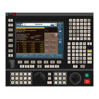
Fagor CNC 8060 Installation Manual (900 pages)
Brand:
Fagor
| Category:
Controller
| Size: 7.06 MB
Table of Contents
Table of Contents
3
About the Product
7
Declaration of Conformity
11
Declaration of Conformity
13
Version History
15
Safety Conditions
17
Warranty Terms
21
Material Returning Terms
23
CNC Maintenance
25
Chapter 1 Software Installation
27
Software Installation at the CNC
27
Work Modes and Software Protection at the CNC
29
Software Installation at the PC (Simulator)
32
Updating the Software Version
34
Software Update Since Previous Versions
35
Requirements before and after CNC Setup
36
Installation of Third-Party Software (CNC 8065 Only)
37
Software Configuration
38
MTB (Machine Tool Builder) Folder
39
USERS Folder
40
Chapter 2 Machine Parameters
43
Parameter Matching between the CNC and the Sercos Drive
43
Parameters to Verify before the Startup
45
General Machine Parameters
47
General Machine Parameters. Execution Channels
76
Machine Parameters for the Axes and Spindles
99
Machine Parameters for the Axes. Work Sets
131
Machine Parameters for JOG Mode
166
Example of How to Set the Handwheels and Jog Keys
171
Machine Parameters for the M Function Table
175
Machine Parameters for Kinetics
177
Definition of the Spindle Kinetics (Types 1 through 8)
181
Definition of the Table Kinetics (Types 9 through 12)
185
Definition of the Kinematics of the Spindle - Table (Types 13 through 16)
189
Definition of the Spindle Kinetics (Types 17 through 24)
193
Definition of the –C– Axis Kinematics (Types 41 through 42)
197
Definition of the –C– Axis Kinematics (Type 43)
199
Definition of the OEM Kinematics (Types 100 through 105)
200
Configuration of Angular Transformations
201
Machine Parameters for the Magazine
203
Chapter 7 Tool and Magazine Management
206
Types of Tool Magazine
206
Machine Parameters for HMI (Interface)
208
OEM Machine Parameters
214
Chapter 3 Introduction to the Plc
220
PLC Program
220
Modular Structure of the PLC Program
221
PLC Resources
223
Operation of a Timer
228
Monostable Mode. TG1 Input
230
Delayed Activation Mode. TG2 Input
232
Delayed Deactivation Mode. TG3 Input
234
Operation of a Counter
238
Chapter 4 Plc Programming
243
Directing Instructions
243
Consulting Instructions
247
Flank Detection Instructions
248
Comparing Instructions
249
Operators and Symbols
250
Action Instructions
251
Assignment Binary Instructions
252
Conditional Binary Instructions
253
Sequence Breaking Action Instructions
254
Arithmetic Action Instructions
255
Logic Action Instructions
257
Specific Action Instructions
259
Action Instruction of the Electronic Cam
262
Instructions for Independent Move: Positioning
264
Instructions for Independent Move: Synchronization
266
Instructions for Coordinate Latching Using a Probe or Digital Input
268
Summary Programming Commands
272
Chapter 5 Cnc-Plc Communication
276
Auxiliary –M– Functions
276
Special Considerations with the Multi-Spindle Option and Channels
277
Auxiliary –H– Functions
278
Special Considerations with the Multi-Spindle Option and Channels
279
Auxiliary –S– Function
280
Special Considerations with the Multi-Spindle Option and Channels
281
Transferring Auxiliary Functions -M-, -H
282
Synchronized Transfer
283
Non-Synchronized Transfer
284
Displaying PLC Errors and Messages
285
Chapter 6 Logic Cnc Inputs and Outputs
288
General Consulting Signals
288
Consulting Signals for Axes and Spindles
298
Consulting Signals for the Spindle
304
Consultation Signals of the Independent Interpolator
306
Tool Manager Consulting Signals
308
Keystroke Consulting Signals
310
General Modifiable Signals
314
Modifiable Signals for Axes and Spindles
323
Spindle Modifiable Signals
327
Modifiable Signals of the Independent Interpolator
331
Tool Manager Modifiable Signals
332
Keystroke Modifiable Signals
335
Types of Tool Magazine
343
Tool Table, Active Tool Table and Tool Magazine Table
345
Communication between Manager and PLC
346
Manager --> PLC Communication
347
PLC --> Manager Communication
348
Manager Emergency
350
Tool Monitoring
351
Variables Related to Tool Magazine Management
352
Tool Loading and Unloading from the Magazines
353
Magazine-Less System
354
Valid Operations and Marks Activated by the PLC with each One of Them
355
Detailed Description of the Operations of the Magazine
356
Basic PLC Programming
357
Communication between the PLC and the M06 Subroutine
363
Program of the M06 Subroutine
364
Basic PLC Programming
367
Synchronous Magazine Without Changer Arm
368
Detailed Description of the Operations of the Magazine
371
Communication between the PLC and the M06 Subroutine
374
Program of the M06 Subroutine
375
Basic PLC Programming
379
Synchronous Magazine with Changer Arm and 1 Claw
381
Valid Operations and Marks Activated by the PLC with each One of Them
382
Detailed Description of the Operations of the Magazine
384
Communication between the PLC and the M06 Subroutine
387
Program of the M06 Subroutine
388
Basic PLC Programming
393
Synchronous Magazine with Changer Arm and 2 Claws
395
Valid Operations and Marks Activated by the PLC with each One of Them
396
Detailed Description of the Operations of the Magazine
398
Communication between the PLC and the M06 Subroutine
401
Program of the M06 Subroutine
402
Basic PLC Programming
407
Asynchronous Magazine with Changer Arm
409
Valid Operations and Marks Activated by the PLC with each One of Them
410
Detailed Description of the Operations of the Magazine
412
Communication between the PLC and the M06 Subroutine
415
Program of the M06 Subroutine
416
Basic PLC Programming
422
Chapter 8 Key Codes
428
Example for Simulating the Keyboard from the PLC
428
Assigning Codes for a Spanish Keyboard
430
Advertisement
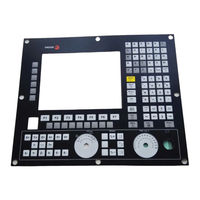
Fagor CNC 8060 Installation Manual (698 pages)
Brand:
Fagor
| Category:
Power Tool
| Size: 6.93 MB
Table of Contents
Table of Contents
3
About the Product - CNC 8060
11
About the Product - CNC 8065
15
Declaration of CE Conformity and Warranty Conditions
19
Version History - CNC 8060
21
Version History - CNC 8065
27
Safety Conditions
33
Returning Conditions
37
CNC Maintenance
39
Chapter 1 Software Installation
43
Software Installation at the CNC
43
Work Modes and Software Protection at the CNC
45
Software Installation at the PC (Simulator)
48
Updating the Software Version
50
Software Update and Incompatibilities (8060)
51
Software Update and Incompatibilities (8065)
52
Requirements before and after CNC Setup
53
Installation of Third-Party Software (CNC 8065 Only)
54
Software Configuration
55
MTB (Machine Tool Builder) Folder
56
USERS Folder
57
Machine Parameters
59
Chapter 2 Machine Parameters
61
Parameter Matching between the CNC and the Sercos Drive
61
Parameters to Verify before the Startup
63
General Machine Parameters
65
Configuring the Axes of the System
66
Configuration of a Tandem System
67
Configuration of a Gantry Axis
71
Configuration of a Multi-Axis Group
74
Configuring the Spindles of the System
76
Time Setting (System)
77
Sercos Bus Configuration
79
Mechatrolink Bus Configuration
80
CAN Bus Configuration
81
Serial Line Configuration
82
Modbus
83
Default Conditions (Sytem)
84
Arithmetic Parameters
85
Cross Compensation Table
87
Volumetric Compensation Tables
90
Execution Times
93
Numbering of the Digital Inputs (Canfagor Bus)
94
Numbering of the Digital Outputs (Canfagor Bus)
95
Numbering of the Digital Inputs (Canopen Bus)
96
Probe Setting
101
Shared PLC Memory
103
Synchronized Switching
104
PWM (Pulse-Width Modulation)
105
Gap Control
107
Leapfrog
112
Compensating the Dispersion by the CO2 Laser Path
113
Backup of Non-Volatile Data
115
Spindle Synchronization
116
PLC Type
117
Zero Offsets
118
Access to the Parameter Table of the Channel
119
General Machine Parameters. Execution Channels
120
Configuring the Axes of the Channel
121
Configuring the Spindles of the Channel
124
Configuration of the C Axis
125
Time Setting (Channel)
126
Configuration of the HSC Mode (Channel)
127
Virtual Tool Axis
131
Default Conditions (Channel)
132
Arc Center Correction
139
Behavior of the Feedrate and the Feedrate Override
140
Override of the Dynamics for HSC
141
Definition of the Subroutines
142
Tabletop Probe Position
145
Block Search
147
Machining Feedrate
148
Rapid Traverse for the Automatic Mode
149
Maximum Acceleration and Jerk on the Tool Path
150
Resonance Frequency of the Machine
151
Withdrawal the Tool
152
Machine Parameters for the Axes and Spindles
153
Type of Axis and Drive
154
Configuring a Sercos Drive
155
Configuring a Mechatrolink Drive
158
Hirth Axis
159
Axis Configuration for Lathe Type Machines
160
Synchronization of Axes and Spindles
161
Configuration of the Rotary Axes
162
Module Configuration (Rotary Axes and Spindle)
164
Configuration of the C Axis
165
Configuration of the Spindle
166
Spindle Override Change While Threading
168
Software Axis Limits
169
Work Zones
170
PLC Offset
171
Dwell for Dead Axes
172
Radius / Diameter
173
Home Search
174
Configuration of the Probing Movement
176
Repositioning of the Axes in Tool Inspection
178
Configure the Maximum Safety Limit for the Feedrate and for the Speed
179
JOG Mode
180
Leadscrew Error Compensation
185
Filters to Eliminate Resonance Frequency
188
Work Sets
191
Machine Parameters for the Axes. Work Sets
192
Loop Setting
196
Rapid Traverse for the Automatic Mode
202
Gain Setting
203
Linear Acceleration
207
Trapezoidal and Square Sine Acceleration
209
Linear Acceleration (G0 Movements)
213
Trapezoidal and Square Sine Acceleration (G0 Movements)
214
Configuration of the HSC Mode
216
Home Search
218
Following Error
223
Axis Lubrication
226
Module Configuration (Rotary Axes and Spindle)
227
Spindle Speed
228
Analog Command Setting
229
Number of the Analog Output and of the Feedback Input Associated with the Axis
230
Set the Drive Associated with the Axes of a Multi-Axis Group
233
Encoder Information
234
Endat Transmission Format
235
SSI Feedback Type
236
Delay Estimate at the Drive
241
Machine Parameters for JOG Mode
242
Configure the Jog Keys
244
Configure the User Keys as Jog Keys
246
HBLS Portable Operator Panel
247
Example of How to Set the Handwheels and Jog Keys
248
Machine Parameters for the M Function Table
252
Machine Parameters for Kinetics
254
Kinematics Configuration
255
Definition of the Spindle Kinetics (Types 1 through 8)
259
Definition of the Table Kinetics (Types 9 through 12)
263
Definition of the Kinematics of the Spindle - Table (Types 13 through 16)
268
Definition of the Spindle Kinetics (Types 17 through 24)
273
Definition of the –C– Axis Kinematics (Types 41 through 42)
277
Definition of the –C– Axis Kinematics (Type 43)
279
Vectorial Definition of Spindle Kinematics (Type 50)
280
Vectorial Definition of Table Kinematics (Type 51)
284
Vectorial Definition of Spindle-Table Kinematics (Type 52)
288
Definition of the OEM Kinematics (Types 100 through 105)
295
Configuration of Angular Transformations
296
Configuration of Angular Transformations (Parameters)
297
Machine Parameters for the Magazine
299
Magazine Data
300
Tool Magazine Management
301
Types of Tool Magazine
303
Machine Parameters for HMI (Interface)
305
Customizing the Softkeys
306
Interface Setting
307
Keyboard Configuration
309
Simulated Jog Keyboard
312
Graphics Configuration
313
OEM Machine Parameters
314
Generic OEM Parameters
316
Cam Editor
318
Chapter 3 Introduction to the Plc
320
PLC Program
320
Modular Structure of the PLC Program
321
PLC Program Execution
322
PLC Resources
323
Numbering of the Physical Inputs and Outputs
326
Operation of a Timer
328
Monostable Mode. TG1 Input
330
Delayed Activation Mode. TG2 Input
332
Operation of a Counter
338
Chapter 4 Plc Programming
347
Consulting Instructions
347
Flank Detection Instructions
348
Comparing Instructions
349
Operators and Symbols
350
Action Instructions
351
Assignment Binary Instructions
352
Conditional Binary Instructions
353
Sequence Breaking Action Instructions
354
Arithmetic Action Instructions
355
Logic Action Instructions
357
Specific Action Instructions
359
Action Instruction of the Electronic Cam
362
Instructions for Independent Move: Positioning
364
Instructions for Independent Move: Synchronization
366
Instructions for Coordinate Latching Using a Probe or Digital Input
368
Considerations for some Functions
372
Summary Programming Commands
374
Chapter 5 Cnc-Plc Communication
378
Auxiliary –M– Functions
378
Special Considerations with the Multi-Spindle Option and Channels
379
Auxiliary –H– Functions
380
Special Considerations with the Multi-Spindle Option and Channels
381
Auxiliary –S– Function
382
Special Considerations with the Multi-Spindle Option and Channels
383
Transferring Auxiliary Functions -M-, -H
384
Synchronized Transfer
385
Non-Synchronized Transfer
386
Displaying PLC Errors and Messages
387
Chapter 6 Logic Cnc Inputs and Outputs
390
General Consulting Signals
390
Consulting Signals for Axes and Spindles
400
Consulting Signals for the Spindle
406
Consultation Signals of the Independent Interpolator
408
Consulting Logic Signals; Laser
410
Tool Manager Consulting Signals
412
Keystroke Consulting Signals
414
General Modifiable Signals
418
Modifiable Signals for Axes and Spindles
429
Spindle Modifiable Signals
433
Modifiable Logic Signals; Laser
437
Modifiable Signals of the Independent Interpolator
439
Tool Manager Modifiable Signals
440
Keystroke Modifiable Signals
443
Chapter 7 Tool and Magazine Management
451
Types of Tool Magazine
451
Tool Table, Active Tool Table and Tool Magazine Table
453
Communication between Manager and PLC
454
Manager --> PLC Communication
455
PLC --> Manager Communication
456
Manager Emergency
458
Tool Monitoring
459
Variables Related to Tool Magazine Management
460
Tool Loading and Unloading from the Magazines
461
Magazine-Less System
462
Valid Operations and Marks Activated by the PLC with each One of Them
463
Detailed Description of the Operations of the Magazine
464
Turret Type Magazine
465
Valid Operations and Marks Activated by the PLC with each One of Them
466
Basic PLC Programming
473
Synchronous Magazine Without Changer Arm
474
Valid Operations and Marks Activated by the PLC with each One of Them
475
Detailed Description of the Operations of the Magazine
477
Program of the M06 Subroutine
481
Basic PLC Programming
483
Synchronous Magazine with Changer Arm and 1 Claw
484
Valid Operations and Marks Activated by the PLC with each One of Them
485
Detailed Description of the Operations of the Magazine
487
Communication between the PLC and the M06 Subroutine
490
Program of the M06 Subroutine
491
Basic PLC Programming
494
Synchronous Magazine with Changer Arm and 2 Claws
496
Valid Operations and Marks Activated by the PLC with each One of Them
497
Detailed Description of the Operations of the Magazine
499
Communication between the PLC and the M06 Subroutine
502
Program of the M06 Subroutine
503
Basic PLC Programming
506
Asynchronous Magazine with Changer Arm
508
Valid Operations and Marks Activated by the PLC with each One of Them
509
Detailed Description of the Operations of the Magazine
511
Communication between the PLC and the M06 Subroutine
515
Program of the M06 Subroutine
516
Basic PLC Programming
519
Chapter 8 Keyboard Simulation Via the Plc. Key Codes
521
Selecting the Language and the Keyboard Distribution
521
Key Codes
523
Keyboard Shortcuts. Cnc's Own Keys
524
Consulting the Last Key Accepted by the CNC
525
Key Codes Depending on Keyboard Layout
527
Scan Codes. Keyboard Distribution "English (United States)
528
Example. Keyboard Simulation Via the PLC
529
Chapter 10 General Setup
535
Configure the Name and Number of Axes and Spindles
535
Configure the Number of Axes and Spindles of the System
536
Configure the Number of Axes and Spindles of the Channels
537
Configuration Examples
538
Milling Machine with 1 Channel, 3 Axes and 1 Spindle
539
Milling Machine with 1 Channel, 5 Axes (2 Free) and 1 Spindle
540
Milling Machine with 3 Channels, 9 Axes and 2 Spindles
541
Lathe with 1 Channel, 3 Axes and 1 Spindle. Configuration of "Plane" Type Axes
543
Lathe with 1 Channel, 3 Axes and 1 Spindle. Configuration of Trihedron Type Axes
544
Lathe with 2 Channels, 4 Axes and 2 Spindles. Configuration of "Plane" Type Axes
546
Lathe with 3 Channels, 6 Axes and 2 Spindles. Configuration of "Plane" Type Axes
547
Chapter 9 Cnc Variables
535
Chapter 11 Configuring an Axis
549
Configure an Axis as Rotary Axis
549
Configure Two Axes as a Tandem Axis
552
Tandem Axis Configuration. Machine Parameters
553
Effect of the Preload
555
Tandem Axis Configuration. Block Diagram
557
Tandem Related Variables
559
Tandem Adjustment Procedure
560
Configure the Number of the Analog Output and of the Feedback Input
561
Multi-Axis Management
564
Configuration of a Multi-Axis Group. Machine Parameters
566
Configuration of a Multi-Axis Group. the PLC Routine Generates an Error
569
Changing the Set and the Gear at the CNC and at the Drive
570
Home Search
573
Home Search (Axes and Spindles)
575
Home Search (Gantry Axes)
578
Software Limits of the Axes
580
How to Set the Software Travel Limits
582
Set the Tolerance for an Axis Located at the Software Travel Limits
584
Chapter 12 Volumetric Compensation
587
Setup
587
PLC. General Modifiable Signals
589
File Containing Basic Volumetric Compensation Data
590
Sequence to Define the Values in the File
591
Variables
593
Variables. General Modifiable Signals
594
Variables. Volumetric Compensation
595
Error Messages (Cause and Solution)
596
Chapter 13 Configuring in Hsc Mode (High Speed Cutting)
600
Configuration of the HSC Mode
600
Influence of the Type of Acceleration and of the Filters in HSC Mode
604
Procedure for Analysis and Adjustment of the HSC
605
Summary of the Useful Variables to Analyze the HSC
608
Variables Associated with Feedrate Limitation
609
Variables Associated with the FEEDRATE on the Tool Path
610
Variables Associated with the Block Being Executed
611
Variables Associated with the Velocity in the Loop
612
The Loops and the Variables
613
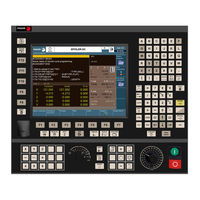
Fagor CNC 8060 Operating Manual (502 pages)
Brand:
Fagor
| Category:
Control Systems
| Size: 6.11 MB
Table of Contents
Table of Contents
3
About the Product - CNC 8060
11
About the Product - CNC 8065
15
Declaration of CE Conformity and Warranty Conditions
21
Version History - CNC 8060
23
Version History - CNC 8065
25
Safety Conditions
29
Returning Conditions
33
CNC Maintenance
35
Chapter 1 Description of the Keys
37
Monitor LCD-15. (8065)
37
1.2 Monitor Lcd-10K (Option 1). (8065).
38
Monitor LCD-10K (Option 1). (8065)
38
F1 F2 F3 F4
40
Auto Manual Edit MDI
40
Function Keys
40
Keys F1 through F12 Select the Options of the
40
Browsing Keys
40
NEXT Key
40
Configurable Key that Can Carry out One of the Following Actions
40
Access the Various Screens of the Active
40
Work Mode Sequentially, Pressing [SHIFT] at the same Time Inverts the Sequence. in the
40
PLC Mode, It Switches between the Various
40
Horizontal Keyb / Horizontal Keyb + Mouse. (8065)
42
Caps Home
43
Shift End
43
Vertical Keyb / Vertical Keyb + Mouse. (8065)
43
Horizontal Keyb. (8060)
44
Vertical Keyb. (8060)
46
Op Panel / Op Panel + Spdl Rate. (8065)
48
Op Panel. (8060)
49
Horizontal Keyb 2.0 + Touchpad (8060/8065)
50
Keyboard Shortcuts
53
Chapter 2 General Concepts
55
Turning the CNC on and off
55
Emergency Shutdown with Battery (8065 Only)
57
Work Modes and Software Protection at the CNC
58
Ethernet
61
Chapter 3 How to Operate the Cnc
63
General Description of the Interface
63
Move the Interface While Dragging It with the Mouse
64
Main Menu
65
Detailed Description of the CNC Status Bar
65
Channel Synchronization Window
67
PLC Messages
68
Horizontal Softkey Menu
69
Operating Modes
70
Work Modes
71
Description of the Various Operating Modes
72
Task Window
74
Windows for Warnings and Errors
75
PLC Errors
77
File Selection Window
78
Calculator
80
Defining Expressions
82
Cnc 8060
83
Dialog Boxes
84
Automatic Mode
85
Interface Description
85
Softkey Menus
87
Display the Status of the Program or of the Active Subroutines
88
Chapter 4 Automatic Mode
89
Program Simulation and Execution
89
Select the First and Last Blocks of the Execution
90
Execute a Program
92
Resume the Execution of a Program from the Block Where It was Canceled
93
Cancel the Execution and Resume from Another Block While Keeping the History
94
Simulated Execution of a Program
95
Execute a Program (Retrace)
98
Executing a Program in 8055 MC/TC Language
101
Executing Program Blocks Separately
102
Tool Inspection
103
Block Search
108
Treatment of Functions M, H, F, S
110
Show/Hide the Dynamic Override of the HSC
111
FFC (Fagor Feed Control)
112
Display the Status of the DMC (Dynamic Machining Control)
113
Learning Phase
114
Deactivating the DMC
115
Manual (Jog) Mode
117
Interface Description
117
Softkey Menus
119
Chapter 5 Manual (Jog) Mode
120
Operations with the Axes
120
Jogging the Axes with Handwheels
123
Moving an Axis to a Particular Position (Coordinate)
125
Spindle Control
126
Tool Selection and Tool Change
127
Setting the Feedrate and Spindle Speed
128
Setting and Activating the Zero Offsets and the Fixture Offsets
129
Chapter 6 Manual (Jog) Mode. Tool Calibration
133
Manual Calibration. Calibration Without a Probe
133
Semi-Automatic Calibration. Calibration with a Probe
137
Automatic Calibration with a Probe and a Canned Cycle
140
Lathe Model ("Plane" Geometrical Configuration)
143
Chapter 7 Jog Mode. Part Centering (Mill Model)
147
How to Define the Data
147
Data Programming
148
Basic Operation
152
EDISIMU Mode
155
Interface Description
155
Softkey Menus
157
Program Editing and Simulation
158
Chapter 8 Edisimu Mode (Editing and Simulation)
159
Editing a Program in the 8055 CNC Language
159
Program Simulation
161
Simulation Errors
163
Editing Window
164
Softkey and Hotkey Menus
166
Contextual Programming Assistance
167
Help for Programming Subroutines
168
Syntax Errors When Editing
169
Working in the Editing Window
170
Operations with Files
172
Customizing the Editor (General Options)
173
Customizing the Editor (Appearance)
175
Chapter 10 Fcas (Fagor Collision Avoidance System)
179
CHAPTER 11 Profile Editor
179
Inclined Planes (·M· Model)
180
Geometric-Help Editor
181
Graphic Assistance for the Program Editor
185
Graphics Window
186
Program Window
187
Working in the Program Window
188
Simulate Program Blocks Separately
190
Display the Status of the Program or of the Active Subroutines
191
Statistics Window
192
Time Estimates
193
Chapter 9 Fmc (Fagor Machining Calculator)
197
FMC Calculator
197
Materials Table
198
Operations Table
199
Working with the FMC
200
FCAS Status
202
FCAS Operation
203
Interface Description
205
How to Use the Profile Editor
207
Define a New Profile, Enlarge an Existing One or Import One from a File
208
Define any Profile Using Straight and Curved Sections
209
Define a Circular Profile
211
Define a Rectangular Profile
212
Import a Profile from a DXF File
213
Modify a Profile and Insert Corners
215
Configuring the Profile Editor. Displayed Area
217
Examples of How to Define Profiles
218
Profile Editor. Example 2 (Milling)
219
Profile Editor. Example 3 (Milling)
221
Profile Editor. Example 4 (Lathe)
222
Description of the Graphic Environment
223
Softkey Menus
224
Type of Graphics
225
Zoom
226
Dimensions
227
Measurement
228
Clear Screen
229
Options
230
Real Coordinates
231
Graphic Environment
233
Horizontal Softkey Menu
236
Move, Rotate and Zoom in or out on the Graphic
237
Select the Type of View
238
Configuring the Graphics Window (Properties of each Window)
239
Configure the Colors for the Tool Path and Solid
242
General Configuration of the Graphics
243
Configuration. Cancel the Graphics
244
Actions. Move the Active Sections
245
Actions. Print the Graphic
246
Editing, Displaying and Hiding Parts
247
Automatic Dimensions
248
Measure the Part
249
Viewing the Tool Paths and the Solid
250
Simulation Speed (Edisimu Mode Only)
251
Description of the Graphic Environment
253
Softkey Menus
254
Type of Graphics
255
Zoom
256
Dimensions
257
Clear Screen
258
Options
259
Real Coordinates
260
CHAPTER 12 Graphic Environment
261
HD Graphics in Automatic Mode
262
HD Graphics in Edisimu Mode
263
Horizontal Softkey Menu
264
Move, Rotate and Zoom in or out on the Graphic
265
Select the Type of View
266
Configuring the Graphics Window (Properties of each Window)
267
Configuring and Activating the Sections
268
Configure the Colors for the Tool Path and Solid
269
General Configuration of the Graphics
270
Configuration. Cancel the Graphics
271
Actions. Move the Active Sections
272
Actions. Print the Graphic
273
Editing, Displaying and Hiding Parts
274
Automatic Dimensions
275
Measure the Part
276
Viewing the Tool Paths and the Solid
277
Simulation Speed (Edisimu Mode Only)
278
MDI/MDA Mode
279
Interface Description
279
Softkey Menus
280
Chapter 15 Graphics Hd (·T· Model)
261
Chapter 16 MDI/Mda Mode
281
Edit and Execute Individual Blocks
281
Block History
282
Chapter 17 User Tables
283
User Table Presentation
283
Softkey Menus
284
Zero Offset Tables
285
Fixture Table
287
Save and Recall Tables
291
Find Text
292
Tool and Magazine Table
293
Chapter 18 Tool and Magazine Table
293
Presentation of the Tool Tables and Magazine Tables
293
Softkey Menus
294
Search for a Text in the Tables
295
Save and Load the Tables
296
Printing the Tables
298
Tool Table
299
Tool and Tool Magazine Table
301
The Tool List
302
Description of the Tool Data
303
Tool Table (Simple Mode)
312
Data of the M Tools (Standard Page - Screen-)
313
Data of the T Tools (Standard Page - Screen-)
314
Data of the M/T Tools (Offset Page - Screen-)
315
Operations with the Tool Table (Full Mode)
316
Active-Tools Table
317
Softkey Menus
318
Table for the Status of the Tool Change Process
319
Magazine Table
320
Softkey Menus
321
List of Magazine Positions
322
Magazine Information
323
Operations with the Magazine Table
325
Load / Unload a Tool to / from the Tool Changer Arm
327
Utilities Mode
329
Interface Description
329
Softkey Menus
331
Chapter 19 Utilities Mode
332
Set How to Display the List of Programs
332
Select Files and Create Folders
333
Search in Files
334
Protection Passwords
335
Data Safety Backup. Backup - Restore
337
Encrypting Files
339
Chapter 20 Plc
341
Appearance of the PLC Mode
341
Icon Description (Vertical Softkeys)
342
Programs" Service
343
Softkey Menus. PLC Project
344
Softkey Menus. Files of the PLC Project
345
Program Editing
346
Editing in C Language or Mnemonic Language
348
Softkey "Analyze
349
Softkey "Operations with Blocks
350
Softkey "Find/Replace
351
Softkey "Customize
352
Editing in Contact (Ladder) Language (Softkeys)
353
Softkey "Analyze
354
Edit" Softkey
355
Softkey "View
357
Softkey "Find
358
Program Monitoring
359
Softkey Menus. Monitoring in C Language or Mnemonic Language
360
Softkey Menus. Monitoring in Contact (Ladder) Language
361
Outputs" Service
364
Softkey Menus. Options of the "Outputs" Service
365
Logic Analyzer" Service
366
Editing Logic Analyzer Data
367
Execute and Analyze Trace
370
Monitoring" Service
371
Description of Resource Tables
372
Definition of the Table Resources
373
Options of the "Monitoring" Service (Softkeys)
374
Cross References" Service
375
Softkey Menus. Options of the "Cross Reference" Service
376
Statistics" Service
377
Softkey Menus. Options of the "Statistics" Service
378
Messages" Service
379
Softkey Menus. Options of the "Messages" Service
380
Editing the Message and Error Table
381
Displaying PLC Messages
382
Displaying PLC Errors
383
Grouping the Additional Information Text Files in a Single File
384
Save, Load and Print a Message and Error Table
385
Chapter 21 Machine Parameters
387
Appearance of the Machine Parameter Tables
387
Softkey Menus
388
Parameter Table Description
389
M" Function Setting Table
390
Compensation Table
391
Kinematics Table
392
OEM Parameters
393
Operations with Tables
394
Save and Recall Tables
395
Find Text
396
Importing and Exporting Compensation Tables
397
Chapter 22 Setup Assistance
400
Oscilloscope
400
Interface Description
401
Chapter 24 Diagnosis
402
Softkey Menus
402
Configuration Screen
405
Configure and Execute the Oscilloscope Function
406
Machine Parameter Editing
407
The Bode Diagram
410
Interface Description
411
Softkey Menus
412
Machine Parameter Editing
415
Configuration Screen
417
The Circularity (Roundness) Test
420
Interface Description
421
Softkey Menus
423
Configuring and Executing the Circularity (Roundness) Test
424
Configure the Graphic Environment
425
Define and Execute the Movement Subroutine
426
Data Capture for the Graphic
427
Adjustment of the Machine Parameters Involved
428
Validate the Changes and Save the Configuration Used
430
Machine Parameters that May be Modified
431
Chapter 23 Ddssetup
433
Appearance of the Ddssetup Mode
433
Icon Description (Vertical Softkeys)
434
List of Devices Connected to the Bus
435
Drives Accessing Level (Only Sercos)
437
Parameters and Variables– Service
438
Error Management– Service
440
Monitoring– Service
441
Information– Service
443
Configuration Diagnosis
453
Software Diagnosis
454
Hardware Diagnosis. Bus CAN, Sercos and Mechatrolink
455
Sercos Diagnosis
457
Save the CAN Configuration for the Start-Up Test
458
Report Generation
459
View the History of Errors and Warnings Issued by the CNC
460
Operating Terms
461
Generating the "Operating Terms" Codes (Only for OEM)
462
Enter the CNC Code to Activate or Cancel the Temporary User License
464
Chapter 25 Apps
466
Send Emails
466
Configure and Activate the Application
468
Configuring Network Properties
470
Chapter 26 Kinematics Calibration
473
Kinematics Calibration (Kinematic Offsets)
473
Page 2. Page to Display the Captured Position Values (Coordinates)
475
Page 3. Page to Display the Calculated Data
476
How to Calibrate a Kinematics
477
Tables to Modify Type 1 to 16 Kinematics to Vector Kinematics
478
Adapting a Type 2 Kinematics to a Type 50 Kinematics
479
Adapting a Type 3 Kinematics to a Type 50 Kinematics
480
Adapting a Type 4 Kinematics to a Type 50 Kinematics
481
Adapting a Type 5 Kinematics to a Type 50 Kinematics
482
Adapting a Type 6 Kinematics to a Type 50 Kinematics
483
Adapting a Type 7 Kinematics to a Type 50 Kinematics
484
Adapting a Type 8 Kinematics to a Type 50 Kinematics
485
Adapting a Type 9 Kinematics to a Type 51 Kinematics
486
Adapting a Type 10 Kinematics to a Type 51 Kinematics
487
Adapting a Type 11 Kinematics to a Type 51 Kinematics
488
Adapting a Type 12 Kinematics to a Type 51 Kinematics
489
Adapting a Type 13 Kinematics to a Type 52 Kinematics
490
Adapting a Type 14 Kinematics to a Type 52 Kinematics
492
Adapting a Type 15 Kinematics to a Type 52 Kinematics
494
Adapting a Type 16 Kinematics to a Type 52 Kinematics
496
Advertisement
Fagor CNC 8060 Operating Manual (172 pages)
Brand:
Fagor
| Category:
Control Systems
| Size: 4.38 MB
Table of Contents
Table of Contents
3
About the Product - CNC 8060
5
About the Product - CNC 8065
9
Declaration of CE Conformity and Warranty Conditions
13
Version History - CNC 8060
15
Version History - CNC 8065
17
Safety Conditions
19
Symbols
20
Symbols
21
Returning Conditions
23
CNC Maintenance
25
Accessing the Conversational Mode
27
Chapter 2 Operating in Jog Mode
30
Introduction
30
Auxiliary Screen of the Conversational Mode
31
Cycle Editing
33
Cycle Simulation
34
Cycle Execution
35
Operations with the Axes
36
Jogging the Axes with Handwheels
39
Moving an Axis to a Particular Position (Coordinate)
41
Spindle Control
42
Tool Selection and Tool Change
43
Setting and Activating the Zero Offsets and the Fixture Offsets
44
Tool Calibration
45
Manual Calibration. Calibration Without a Probe
46
Semi-Automatic Calibration. Calibration with a Probe
49
Automatic Calibration with a Probe and a Canned Cycle
52
CHAPTER 1 General Concepts
55
Chapter 3 Working with Operations or Cycles
56
G Functions Associated with the Execution of the Cycles
56
Configuring the Cycle Editor
57
Teach-In Mode
58
Work Planes and Shifting of the Machining Operations
59
Selecting Data, Profiles and Icons
61
Value Applied When the Value of a Parameter Is 0
62
Associate a Multiple Machining Operation with a Canned Cycle
63
Center Punching
64
Basic Operation
66
Drilling
67
Basic Operation
68
Deep Hole Drilling
69
Basic Operation
70
Tapping
74
Basic Operation
76
Thread Milling
77
Basic Operation
79
Reaming
80
Boring
82
Basic Operation
83
Boring with Spindle Orientation
84
Basic Operation
86
Simple Rectangular Pocket
87
Basic Operation
90
Rectangular Pocket with Rounding
91
Basic Operation
95
Circular Pocket
96
Basic Operation
100
Pre-Emptied Circular Pocket
101
Basic Operation
104
D Profile Pocket
106
Executable Pocket File
110
Basic Operation
111
Examples of How to Define 2D Profiles
112
D Profile Pocket with Islands
115
Executable Pocket File
121
Basic Operation
122
Examples of How to Define 3D Profiles
123
Rectangular Boss
126
Basic Operation
130
Circular Boss
131
Basic Operation
134
Surface Milling
135
Basic Operation
138
Point-To-Point Profile Milling
139
Basic Operation
142
Free Profile Milling
143
Basic Operation
146
Slot Milling
147
Basic Operation
151
Multiple Machining in Straight Line
153
Multiple Machining in Arc Pattern
154
Multiple Machining in Rectangular Pattern
156
Multiple Machining in Grid Pattern
157
Random Multiple Machining
158
Fagor CNC 8060 Translation Of The Original Manual (180 pages)
Remote modules
Brand:
Fagor
| Category:
Control Unit
| Size: 9.79 MB
Table of Contents
About the Product - Cnc 8060
5
Basic Characteristics
5
Software Options
6
About the Product - Cnc 8065
9
Declaration of Ce Conformity and Warranty Conditions
15
Warranty Terms
15
Version History - Cnc 8060
17
Version History - Cnc 8065
19
Safety Conditions
21
Safety Symbols
22
Returning Conditions
25
Cnc Maintenance
27
About this Manual
29
Installation and Start-Up
29
Hardware Structure
31
Probe Connection
34
Power Supply
38
Digital Inputs and Outputs
41
Analog Inputs and Outputs
43
Digital In/Out
64
Mechanical Characteristics
75
Electromagnetic Compatibility
75
Ambient Conditions
75
Degree of Protection
76
Installation of the Modules
81
Ground Connection
81
Shield Connection
81
Cable Connection
83
Node Configuration
88
Module Dimensions
113
Mounting the Module
114
Power Supply Requirements
115
Digital Inputs
116
Digital Outputs
116
Analog Inputs
116
Analog Outputs
116
Description of Connectors
118
DC Supply Input
119
CAN Bus Connection
123
Cable Characteristics
123
Specifications
128
Securing the Module
130
Connector Pinout
131
Module Identification
144
Parameter Setting Example
147
Type of Error
151
Error Information
159
Software Installation/Update
161
Communication Parameters
163
CAN Connector
165
Cable Handling
174
Node Identification
175
User Notes
177
Fagor CNC 8060 Manual (148 pages)
Remote modules
Brand:
Fagor
| Category:
Remote Control
| Size: 1.98 MB
Table of Contents
Table of Contents
3
About the Product
5
Declaration of Conformity
7
Version History
11
Safety Conditions
13
Warranty Terms
17
Material Returning Terms
19
CNC Maintenance
21
Chapter 1 Previous Information
27
Chapter 2 Hardware Structure
27
Chapter 3 Rio70 Remote Modules. (Canfagor Protocol)
27
Dimensions and Mounting of the Modules
27
Consumption of the Remote Modules
29
Power Supply
30
Elements (Connectors)
31
Digital Inputs and Outputs
33
Analog Inputs and Outputs
35
Feedback Inputs (Counter)
37
Elements (Connectors)
38
Electrical Characteristics of the Inputs and Outputs
39
Feedback Inputs. Technical Characteristics and Connection
40
Numbering of the Digital Inputs and Outputs
42
Numbering of the Analog Inputs and Outputs and of the Feedback Inputs
44
Probe Connection
45
Chapter 4 Rio5 Remote Modules. (Canopen Protocol)
49
Dimensions and Mounting of the Modules
49
Power Supply
50
Elements (Connectors)
52
Digital Inputs and Digital Outputs (Single Module)
56
Elements (Connectors)
59
Electrical Characteristics of the Inputs and Outputs
60
Numbering of the Digital Inputs and Outputs
61
Numbering of the Analog Inputs and Outputs and of the Temperature Sensor Inputs
63
Chapter 5 Riow Remote Modules. (Canopen Protocol)
65
Dimensions of the Modules
65
Technical and Electrical Characteristics
66
Electrical Characteristics of the Inputs and Outputs
68
RIOW-CANOPEN-ECO Module. Leading (First) Module
75
Elements (Connectors)
76
Node Configuration
77
Meaning of the Led's
79
Elements (Connectors)
83
Voltage Supply for the Module
85
Node Configuration
86
Meaning of the Led's
88
RIOW-PS24 Module
91
Elements (Connectors)
92
RIOW-8DI Module. Module of 8 Digital Inputs
93
Elements (Connectors)
94
RIOW-8DO Module. Module of 8 Digital Outputs
95
RIOW-4AI Module. Module of 4 Analog Inputs
97
RIOW-4AO Module. Module of 4 Analog Outputs
99
Elements (Connectors)
100
RIOW-2AI-PT100 Module. Module of 2 Inputs for PT100 Temperature Sensors
101
RIOW-END Module. Last Module of the Group
103
Numbering of the Digital Inputs and Outputs
104
Numbering of the Analog Inputs and Outputs and of the Temperature Sensor Inputs
106
Fagor CNC 8060 Users Quick Reference (170 pages)
Brand:
Fagor
| Category:
Control Systems
| Size: 7.82 MB
Table of Contents
Table of Contents
3
Screen and Keys
5
Work Modes
13
ISO Language
45
ISO Canned Cycles (M)
65
ISO Canned Cycles (T)
83
Conversational Mode
103
Conversational Cycles (M)
119
Conversational Cycles (T)
129
Measuring and Calibration Cycles (M)
137
Measuring and Calibration Cycles (T)
147
High Level Language
151
Fagor CNC 8060 Hardware Configuration (113 pages)
Brand:
Fagor
| Category:
Control Systems
| Size: 2.79 MB
Table of Contents
About the Product - Cnc 8060
5
Basic Characteristics
5
Software Options
6
Declaration of Ce Conformity and Warranty Conditions
9
Warranty Terms
9
Version History - Cnc 8060
11
Safety Conditions
13
Safety Symbols
14
Returning Conditions
17
Cnc Maintenance
19
About this Manual
21
Installation and Start-Up
21
Operator Panels
24
Remote Modules
25
General Diagram
26
Enclosure Requirements
27
Specifications
32
Securing the Module
39
Digital Inputs
52
Digital Outputs
52
Analog Outputs
52
Connector Pinout
55
Feedback Connection
56
Cable Characteristics
56
Transmission Speed
61
Specifications
65
General Diagram
66
Enclosure Design
68
Securing the Module
69
Changing the Input Language
72
Numeric Keypad
73
Connector Pinout
80
Ground Connection
81
Rear Connectors
81
Handwheel Connection
85
Cable Characteristics
85
CAN Connector
99
Cable Handling
106
Module Identification
107
Electrical Diagram
109
User Notes
110
Fagor CNC 8060 Manual (96 pages)
Brand:
Fagor
| Category:
Control Systems
| Size: 4.87 MB
Table of Contents
Table of Contents
3
About this Manual
5
About the Product Quercus CNC 8060
7
About the Product Quercus CNC 8065
13
Declaration of CE Conformity and Warranty Conditions
19
Safety Conditions
21
Returning Conditions
25
CNC Maintenance
27
New Features
29
Capítulo 1 Previous Notions about the Probe
32
Activate the Probe
32
Geometric Configuration of Axes and Work Planes
34
Behavior of the Feedrate in Probing Movements
35
First and Last Subroutines of the Probing Cycles
36
Subroutines Supplied by Fagor
37
Safe Probing Cycles
39
Capítulo 2 Probing
41
G100/G103. Probing
41
G101/G102. Include/Exclude the Measuring Error in the Theoretical Coordinate
44
G104. Probe Movement up to the Programmed Position
47
Properties of Measurement Related Variables
48
Capítulo 3 Canned Cycles. Iso Coded Programming
51
PROBE 1. Tool Calibration
51
Programming the Cycle
53
Basic Operation
54
PROBE 2. Tabletop Probe Calibration
56
Programming the Cycle
58
Basic Operation
59
PROBE 3. Part Measuring Along the Ordinate Axis
61
Programming the Cycle
62
Basic Operation
63
PROBE 4. Part Measuring Along the Abscissa Axis
64
Programming the Cycle
65
Basic Operation
66
Check the Data of the Canned Cycles (Variables)
67
Capítulo 4 Canned Cycles. Cycle Editor
70
How to Define the Data of the Editor
70
Tool Calibration
71
Programming the Cycle
73
Basic Operation
75
Tabletop Probe Calibration
77
Programming the Cycle
79
Basic Operation
81
Part Measuring Along the Ordinate Axis
83
Programming the Cycle
84
Basic Operation
86
Cnc 8060
86
Part Measuring Along the Abscissa Axis
87
Cnc 8065
87
Programming the Cycle
88
Basic Operation
90
Simulating a Cycle from the Editor
91
Advertisement
Related Products
Fagor CNC 8065
Fagor CNC 8055i FL EN
Fagor CNC 8055 FL
Fagor CNC 8055i FL
Fagor CNC 8055 Power
Fagor CNC 8060 LASER
Fagor CNC 8060 T FL
Fagor CNC 8060 T Power
Fagor CNC 8060 L
Fagor Quercus CNC 8065 T
Fagor Categories
Dishwasher
Refrigerator
Oven
Ventilation Hood
Hob
More Fagor Manuals
Login
Sign In
OR
Sign in with Facebook
Sign in with Google
Upload manual
Upload from disk
Upload from URL