Sign In
Upload
Manuals
Brands
Endress+Hauser Manuals
Measuring Instruments
Proline Promass F 300
Endress+Hauser Proline Promass F 300 Manuals
Manuals and User Guides for Endress+Hauser Proline Promass F 300. We have
1
Endress+Hauser Proline Promass F 300 manual available for free PDF download: Operating Instructions Manual
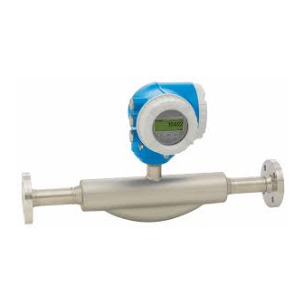
Endress+Hauser Proline Promass F 300 Operating Instructions Manual (264 pages)
Coriolis Flowmeter EtherNet / IP
Brand:
Endress+Hauser
| Category:
Measuring Instruments
| Size: 7.67 MB
Table of Contents
Table of Contents
3
1 About this Document
6
Document Function
6
Symbols Used
6
Safety Symbols
6
Electrical Symbols
6
Communication Symbols
7
Tool Symbols
7
Symbols for Certain Types of Information
7
Symbols in Graphics
8
Documentation
8
Standard Documentation
8
Symbols on Measuring Device
8
Supplementary Device-Dependent Documentation
9
Registered Trademarks
9
2 Basic Safety Instructions
10
Requirements for the Personnel
10
Designated Use
10
Workplace Safety
11
Operational Safety
11
Product Safety
12
IT Security
12
Device-Specific IT Security
12
Protecting Access Via Hardware Write Protection
12
Protecting Access Via a Password
13
Access Via Fieldbus
13
Access Via Web Server
14
Access Via CDI-RJ45 Service Interface
14
3 Product Description
15
Product Design
15
4 Incoming Acceptance and Product
16
Identification
16
Incoming Acceptance
16
Product Identification
17
Transmitter Nameplate
18
Sensor Nameplate
19
5 Storage and Transport
21
Storage Conditions
21
Transporting the Product
21
Measuring Devices Without Lifting Lugs
21
Measuring Devices with Lifting Lugs
22
Transporting with a Fork Lift
22
Packaging Disposal
22
6 Installation
23
Installation Conditions
23
Mounting Position
23
Requirements from Environment and Process
26
Special Mounting Instructions
28
Mounting the Measuring Device
30
Required Tools
30
Preparing the Measuring Device
30
Turning the Transmitter Housing
31
Turning the Display Module
31
Post-Installation Check
32
Electrical Connection
33
Connection Conditions
33
Required Tools
33
Requirements for Connecting Cable
33
Device Plugs Available
36
Pin Assignment of Device Plug
36
Terminal Assignment
36
Preparing the Measuring Device
37
Connecting the Measuring Device
37
Connecting the Transmitter
37
Integrating the Transmitter into a Network
41
Connecting the Remote Display and Operating Module DKX001
43
Ensure Potential Equalization
43
Requirements
43
Special Connection Instructions
44
Connection Examples
44
Hardware Settings
47
Setting the Device Address
47
Activating the Default IP Address
48
Ensuring the Degree of Protection
49
Post-Connection Check
49
Operation Options
50
Overview of Operation Options
50
Structure and Function of the Operating Menu
51
Structure of the Operating Menu
51
Operating Philosophy
53
Access to the Operating Menu Via the Local Display
54
Operational Display
54
Navigation View
56
Editing View
58
Operating Elements
60
Opening the Context Menu
61
Navigating and Selecting from List
62
Calling the Parameter Directly
63
Calling up Help Text
63
Changing the Parameters
64
User Roles and Related Access Authorization
64
Code
65
Disabling Write Protection Via Access
65
Enabling and Disabling the Keypad
65
Access to the Operating Menu Via the Web Browser
66
Function Range
66
Prerequisites
66
Establishing a Connection
68
Logging on
70
User Interface
71
Disabling the Web Server
72
Logging out
72
Access to the Operating Menu Via the Operating Tool
73
Connecting the Operating Tool
73
Fieldcare
77
Devicecare
78
9 System Integration
79
Overview of Device Description Files
79
Current Version Data for the Device
79
Operating Tools
79
Overview of System Files
80
Integrating the Measuring Device in the
80
Cyclic Data Transmission
80
Block Model
80
Input and Output Groups
82
Diagnostic Information Via Ethernet/Ip
93
10 Commissioning
98
Function Check
98
Switching on the Measuring Device
98
Connecting Via Fieldcare
98
Setting the Operating Language
98
Configuring the Measuring Device
99
Defining the Tag Name
101
Setting the System Units
101
Configuring the Communication
103
Interface
106
Displaying the I/O Configuration
107
Configuring the Current Input
107
Configuring the Status Input
109
Configuring the Current Output
109
Configuring the Pulse/Frequency
114
Switch Output
114
10.5.10 Configuring the Relay Output
125
10.5.11 Configuring the Local Display
128
10.5.12 Configuring the Low Flow Cut off
139
10.5.13 Configuring the Partial Filled Pipe
140
Advanced Settings
141
Using the Parameter to Enter the Access Code
142
Calculated Values
142
Carrying out a Sensor Adjustment
143
Configuring the Totalizer
144
Carrying out Additional Display Configurations
147
WLAN Configuration
158
Configuration Management
160
Using Parameters for Device Administration
161
Simulation
163
Protecting Settings from Unauthorized
167
Access
167
Write Protection Via Access Code
167
Write Protection Via Write Protection
169
Switch
169
11 Operation
170
Reading the Device Locking Status
170
Adjusting the Operating Language
170
Configuring the Display
170
Reading Measured Values
170
Measured Variables" Submenu
171
Totalizer" Submenu
173
Input Values" Submenu
173
Output Values
175
Adapting the Measuring Device to the Process
177
Conditions
177
Performing a Totalizer Reset
177
Function Scope of the "Control Totalizer" Parameter
178
Function Scope of the "Reset All Totalizers" Parameter
178
Showing Data Logging
179
12 Diagnostics and Troubleshooting
184
General Troubleshooting
184
Diagnostic Information Via Light Emitting
187
Diodes
187
Transmitter
187
Diagnostic Information on Local Display
189
Diagnostic Message
189
Calling up Remedial Measures
191
Diagnostic Information in the Web Browser
192
Diagnostic Options
192
Calling up Remedy Information
193
Diagnostic Information in Devicecare or
193
Fieldcare
193
Diagnostic Options
193
Calling up Remedy Information
194
Diagnostic Information Via Communication
194
Interface
194
Reading out Diagnostic Information
194
Adapting the Diagnostic Information
195
Adapting the Diagnostic Behavior
195
Overview of Diagnostic Information
195
Diagnostic of Sensor
195
Diagnostic of Electronic
197
Diagnostic of Configuration
201
Diagnostic of Process
205
Pending Diagnostic Events
209
12.10 Diagnostic List
210
12.11 Event Logbook
211
12.11.1 Reading out the Event Logbook
211
12.11.2 Filtering the Event Logbook
211
12.11.3 Overview of Information Events
212
12.12 Resetting the Measuring Device
213
12.12.1 Function Scope of the "Device Reset" Parameter
213
12.13 Device Information
214
12.14 Firmware History
215
13 Maintenance
216
Maintenance Tasks
216
Exterior Cleaning
216
Interior Cleaning
216
Measuring and Test Equipment
216
Endress+Hauser Services
216
14 Repairs
217
General Notes
217
Repair and Conversion Concept
217
Notes for Repair and Conversion
217
Spare Parts
217
Endress+Hauser Services
217
Return
217
Disposal
218
Removing the Measuring Device
218
Disposing of the Measuring Device
218
15 Accessories
219
Device-Specific Accessories
219
For the Transmitter
219
For the Sensor
220
Communication-Specific Accessories
220
Service-Specific Accessories
220
System Components
221
16 Technical Data
222
Application
222
Function and System Design
222
Input
223
Output
226
Power Supply
231
Performance Characteristics
232
Installation
237
Environment
237
Process
238
16.10 Mechanical Construction
242
16.11 Operability
246
16.12 Certificates and Approvals
251
16.13 Application Packages
253
16.14 Accessories
255
Supplementary Documentation
255
Index
257
Advertisement
Advertisement
Related Products
Endress+Hauser prolevel FMC 661
Endress+Hauser Levelflex FMP54
Endress+Hauser prosonic flow 92
Endress+Hauser Waterpilot FMX21
Endress+Hauser Proline Prowirl F 200
Endress+Hauser Waterpilot FMX167
Endress+Hauser Liquiphant S FTL71-**********N Series
Endress+Hauser Nivocompact FTC 131
Endress+Hauser Nivocompact FTC 231
Endress+Hauser Gammapilot FTG20
Endress+Hauser Categories
Measuring Instruments
Transmitter
Radar
Switch
Accessories
More Endress+Hauser Manuals
Login
Sign In
OR
Sign in with Facebook
Sign in with Google
Upload manual
Upload from disk
Upload from URL