Sign In
Upload
Manuals
Brands
Emerson Manuals
Measuring Instruments
Rosemount 8750W
User Manuals: Emerson Rosemount 8750W Flow Meter
Manuals and User Guides for Emerson Rosemount 8750W Flow Meter. We have
5
Emerson Rosemount 8750W Flow Meter manuals available for free PDF download: Reference Manual, Quick Start Manual
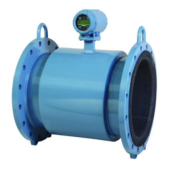
Emerson Rosemount 8750W Reference Manual (264 pages)
Magnetic Flowmeter Platform for Utility, Water, and Wastewater Applications
Brand:
Emerson
| Category:
Measuring Instruments
| Size: 16.94 MB
Table of Contents
Table of Contents
3
System Description
13
Product Recycling/Disposal
14
Introduction
15
Safety Messages
15
Transmitter Symbols
16
Pre-Installation
17
Installation Procedures
17
Transmitter Installation
17
Identify Options and Configurations
17
Mechanical Considerations
18
Electrical Considerations
21
Environmental Considerations
21
Handling and Lifting
22
Mounting
23
Upstream/Downstream Piping
23
Flow Direction
23
Sensor Location
24
Electrode Orientation
24
Sensor Installation
25
Flanged Sensors
25
Flange Bolts
25
Process Reference Connection
29
Wiring the Transmitter
31
Conduit Entries and Connections
32
Conduit Requirements
32
Connecting Sensor to Transmitter
32
Rosemount 8750W Transmitter Terminal Block Connections
36
Analog Output
37
Powering the Transmitter
40
Field Mount Transmitter Cover Jam Screw
44
Basic Configuration
44
Basic Setup
44
Introduction
49
Safety Messages
49
Hardware Switches
49
Alarm Mode
49
Transmitter Security
50
Internal/External Analog Power
50
Internal/External Pulse Power
50
Changing Hardware Switch Settings
50
Additional Loops
52
Connect Pulse Output
52
Connect Discrete Output
56
Connect Discrete Input
58
Process Reference Connection
60
Coil Housing Configuration
60
Introduction
61
Field Mount Transmitter Local Operator Interface (LOI)
61
Basic Features
62
Data Entry
62
Data Entry Examples
63
Totalizer Functionality
64
Display Lock
64
Diagnostic Messages
65
Display Symbols
65
Wall Mount Transmitter Local Operator Interface (LOI)
68
Basic Features
68
Data Entry
68
Data Entry Examples
69
Totalizer Functionality
70
Diagnostic Messages
70
Display Symbols
70
Field Communicator Interface
72
Field Communicator User Interface
72
March
73
Process Variables
94
PV - Primary Variable
94
PV - Percent of Range
94
PV - Analog Output
95
Pulse Output
95
Introduction
97
Configure Outputs
97
Analog Output
97
Pulse Output
100
Totalizer
104
Discrete Input/Output
106
Configure HART
113
Variable Mapping
113
Poll Address
115
Burst Mode
115
Configure LOI
116
Additional Parameters
118
Coil Drive Frequency
118
Process Density
119
Reverse Flow
119
Low Flow Cutoff
119
PV Damping
120
Signal Processing
120
Configure Special Units
122
Base Volume Unit
122
Conversion Factor
122
Base Time Unit
123
Special Volume Unit
123
Special Flow Rate Unit
123
Introduction
125
Licensing and Enabling
126
Licensing the Rosemount 8750W Diagnostics
127
Tunable Empty Pipe Detection
127
Tunable Empty Pipe Parameters
128
Optimizing Tunable Empty Pipe
129
Electronics Temperature
129
Turning Electronics Temperature On/Off
130
Electronics Temperature Parameters
130
Ground/Wiring Fault Detection
130
Turning Ground/Wiring Fault On/Off
131
Ground/Wiring Fault Parameters
131
High Process Noise Detection
131
Turning High Process Noise On/Off
132
High Process Noise Parameters
132
Coated Electrode Detection
133
Turning Coated Electrode Detection On/Off
133
Coated Electrode Parameters
133
4-20 Ma Loop Verification
135
Initiating 4-20 Ma Loop Verification
135
4-20 Ma Loop Verification Parameters
135
SMART™ Meter Verification
136
Sensor Baseline (Signature) Parameters
137
Establishing the Sensor Baseline (Signature)
138
SMART Meter Verification Test Criteria
139
Run Manual SMART Meter Verification
140
Test Conditions
140
Test Scope
141
Continuous SMART Meter Verification
141
SMART Meter Verification Test Results
143
SMART Meter Verification Measurements
145
Optimizing the SMART Meter Verification
148
1Optimizing Continuous SMART Meter Verification
148
Calibration Verification Report
149
Introduction
151
Safety Messages
151
High Process Noise Diagnostic
152
Process Noise Profiles
152
1/F Noise
152
Spike Noise
152
White Noise
152
Optimizing Flow Reading in Noisy Applications
153
Coil Drive Frequency
153
Auto Zero
153
Digital Signal Processing (DSP)
154
Explanation of Signal Processing Algorithm
157
Introduction
159
Safety Information
159
Installing a Local Operator Interface (LOI)
160
Replacing the Rosemount 8750W Transmitter Electronics Stack
161
Field Mount Transmitter
161
Replacing the Terminal Block
163
Removing the Terminal Block
163
Installing the Terminal Block
163
Trims
164
D/A Trim
164
Scaled D/A Trim
165
Digital Trim
165
Universal Trim
167
Review
167
Introduction
169
Safety Messages
169
Installation Check and Guide
170
Transmitter
170
Sensor
170
Remote Wiring
171
Process Fluid
171
Diagnostic Messages
172
Troubleshooting Empty Pipe
177
Troubleshooting Ground/Wiring Fault
178
Troubleshooting High Process Noise
178
Troubleshooting Coated Electrode Detection
180
Troubleshooting 4-20 Ma Loop Verification
180
Troubleshooting the SMART Meter Verification Test
181
Basic Troubleshooting
182
Sensor Troubleshooting
186
Installed Sensor Tests
187
Uninstalled Sensor Tests
189
Technical Support
190
Service
190
Field Mount Transmitter Specifications
191
A.1.1 Functional Specifications
191
A.1.2 Advanced Diagnostics Capabilities
192
A.1.3 Output Signals
193
A.1.4 Sensor Compensation
194
A.1.5 Performance Specifications
194
A.1.6 Analog Output Effects
194
A.1.7 Physical Specifications
195
Wall Mount Transmitter Specifications
195
A.2.1 Functional Specifications
195
A.2.2 Advanced Diagnostics Capabilities
197
A.2.3 Output Signals
197
A.2.4 Sensor Compensation
198
A.2.5 Performance Specifications
198
A.2.6 Analog Output Effects
198
A.2.7 Physical Specifications
199
A.3 Sensor Specifications
199
A.3.1 Functional Specifications
199
A.3.2 Physical Specifications
201
B.2 Certifications
205
Factory Mutual (FM)
205
B.2.2 Csa
206
March
206
B.1 European Directive Information
205
Electro Magnetic Compatibility (EMC)(2004/108/EC) and (2014/30/EU)
205
Low Voltage Directive (LVD) (2006/95/EC) and (2014/35/EU)
205
Ingress Protection Rating for Dust and Water
205
European Pressure Equipment Directive (PED) (97/23/EC) and (2014/68/EU)
205
B.1.5 Rosemount 8750W Flanged Flowtubes
205
B.3 IEC EC and ATEX Approval Information
210
Aappendix C: Wiring Diagrams
213
Emerson ™ 775 Wireless THUM™ Adapter
230
475 Field Communicator
231
Safety Messages
233
Universal Capability
233
D.1 Safety Messages
233
Three-Step Process
234
Rosemount Sensors
237
Rosemount 8750W Sensors to Transmitter
237
D.2 Rosemount Sensors
237
Connecting Sensors of Other Manufacturers
238
Brooks Sensors
239
Model 5000 Sensor to Rosemount 8750W Transmitter
239
D.3 Brooks Sensors
239
Model 7400 Sensor to Rosemount 8750W Transmitter
240
Endress and Hauser Sensors
241
Endress and Hauser Sensor to Rosemount 8750W Transmitter
241
Fischer and Porter Sensors
242
Model 10D1418 Sensor to Rosemount 8750W Transmitter
242
Model 10D1419 Sensor to Rosemount 8750W Transmitter
243
Model 10D1430 Sensor (Remote) to Rosemount 8750W Transmitter
244
Model 10D1430 Sensor (Integral) to Rosemount 8750W Transmitter
245
Model 10D1465 and Model 10D1475 Sensors (Integral) to Rosemount 8750W Transmitter
246
Fischer and Porter Sensor to Rosemount 8750W Transmitter
247
Foxboro Sensors
248
Series 1800 Sensor to Rosemount 8750W Transmitter
248
D.6 Foxboro Sensors
248
Series 1800 (Version 2) Sensor to Rosemount 8750W Transmitter
249
Series 2800 Sensor to 8750W Transmitter
250
Foxboro Sensor to 8750W Transmitter
251
Kent Veriflux VTC Sensor
252
Veriflux VTC Sensor to 8750W Transmitter
252
Kent Sensors
253
Kent Sensor to Rosemount 8750W Transmitter
253
D.8 Kent Sensors
253
Krohne Sensors
254
Krohne Sensor to Rosemount 8750W Transmitter
254
March
254
Taylor Sensors
255
Series 1100 Sensor to Rosemount 8750W Transmitter
255
D.10 Taylor Sensors
255
Taylor Sensor to Rosemount 8750W Transmitter
256
Yamatake Honeywell Sensors
257
Yamatake Honeywell Sensor to Rosemount 8750W Transmitter
257
Yokogawa Sensors
258
Yokogawa Sensor to Rosemount 8750W Transmitter
258
D.12 Yokogawa Sensors
258
Generic Manufacturer Sensors
259
Identify the Terminals
259
Wiring Connections
259
Advertisement
Emerson Rosemount 8750W Reference Manual (214 pages)
Transmitter with Modbus
Brand:
Emerson
| Category:
Transmitter
| Size: 10.52 MB
Table of Contents
Table of Contents
3
Chapter 1 Safety Messages
5
Chapter 2 Introduction
9
System Description
9
Product Recycling/Disposal
9
Chapter 3 Sensor Installation
11
Handling and Lifting Safety
11
Location and Position
12
Sensor Installation
14
Process Reference Connection
19
Chapter 4 Remote Transmitter Installation
23
Pre-Installation
23
Transmitter Symbols
27
Mounting
28
Wiring
29
Chapter 5 Basic Configuration
45
Cover Jam Screw (Field Mount Transmitter Only)
45
Basic Setup
45
Modbus Configuration
49
Local Operator Interface (LOI)
50
Chapter 6 Advanced Installation Details
51
Hardware Switches
51
Additional Loops
54
Chapter 7 Operation
65
Introduction
65
Local Operator Interface (LOI)
65
Chapter 8 Advanced Configuration Functionality
77
Introduction
77
Configure Outputs
77
Configure LOI
95
Additional Parameters
97
Configure Special Units
99
Chapter 9 Advanced Diagnostics Configuration
103
Introduction
103
Modbus Communication Diagnostics
104
Licensing and Enabling
105
Tunable Empty Pipe Detection
106
Electronics Temperature
108
Ground/Wiring Fault Detection
109
High Process Noise Detection
110
Coated Electrode Detection
111
SMART ™ Meter Verification
112
Run Manual SMART Meter Verification
115
Continuous SMART Meter Verification
117
SMART Meter Verification Test Results
118
SMART Meter Verification Measurements
120
Optimizing the SMART Meter Verification
121
Chapter 10 Digital Signal Processing
125
Introduction
125
Safety Messages
125
Process Noise Profiles
126
High Process Noise Diagnostic
127
Optimizing Flow Reading in Noisy Applications
127
Explanation of Signal Processing Algorithm
130
Chapter 11 Maintenance
133
Introduction
133
Safety Information
133
Installing a Local Operator Interface (Field Mount)
134
Installing a Local Operator Interface (Wall Mount)
135
Replacing Electronics Stack (Field Mount)
136
Replacing Electronics Stack (Wall Mount)
138
Replacing a Socket Module/Terminal Block
139
Trims
143
Review
145
Chapter 12 Troubleshooting
147
Introduction
147
Safety Information
148
Installation Check and Guide
148
Diagnostic Messages
150
Basic Troubleshooting
159
Sensor Troubleshooting
162
Installed Sensor Tests
164
Uninstalled Sensor Tests
166
Technical Support
169
Service
170
Appendix A Product Specifications
171
Rosemount 8700M Flowmeter Platform Specifications
171
Transmitter Specifications
175
A.2 Transmitter Specifications
175
Sensor Specifications
183
A.3 Sensor Specifications
183
Appendix B Product Certifications
189
Appendix C Mobus Coil and Register Map
191
Appendix D Wiring Diagrams
207
Installation and Wiring Drawings
208
Emerson Rosemount 8750W Reference Manual (192 pages)
Transmitter with Fieldbus Protocol
Brand:
Emerson
| Category:
Transmitter
| Size: 9.45 MB
Table of Contents
Table of Contents
3
Chapter 1 Safety Messages
7
Chapter 2 Introduction
11
System Description
11
Product Recycling/Disposal
12
Chapter 3 Sensor Installation
13
Handling and Lifting Safety
13
Location and Position
13
Sensor Installation
16
Process Reference Connection
20
Chapter 4 Remote Transmitter Installation
25
Pre-Installation
25
Transmitter Symbols
28
Mounting
28
Wiring
30
Cover Jam Screw
51
Chapter 5 Basic Configuration
53
Communication Methods
53
FOUNDATION Fieldbus Configuration
53
Basic Setup
55
Chapter 6 Advanced Installation Details
57
Hardware Switches
57
Connect Pulse Output
60
Coil Housing Configuration
65
Chapter 7 Advanced Configuration Functionality
73
Introduction
73
Configure Outputs
73
Configure Loi/Display
80
Signal Processing
81
Chapter 8 Advanced Diagnostics Configuration
85
Introduction
85
Licensing and Enabling
86
Tunable Empty Pipe Detection
87
Electronics Temperature
88
Ground/Wiring Fault Detection
89
High Process Noise Detection
90
Coated Electrode Detection
91
SMART ™ Meter Verification
92
Run Manual SMART Meter Verification
95
Continuous SMART Meter Verification
97
SMART Meter Verification Test Results
97
SMART Meter Verification Measurements
98
Optimizing the SMART Meter Verification
100
Chapter 9 Digital Signal Processing
103
Introduction
103
Process Noise Profiles
103
High Process Noise Diagnostic
103
Optimizing Flow Reading in Noisy Applications
104
Explanation of Signal Processing Algorithm
107
Chapter 10 Maintenance
109
Introduction
109
Safety Information
109
Installing a Loi/Display (Field Mount)
110
Installing a Loi/Display (Wall Mount)
111
Replacing Electronics Stack (Field Mount)
112
Replacing Electronics Stack (Wall Mount)
113
Replacing a Socket Module/Terminal Block
115
Trims
119
Review
120
Chapter 11 Troubleshooting
121
Introduction
121
Safety Information
121
Installation Check and Guide
122
Diagnostic Messages
123
Basic Troubleshooting
132
Sensor Troubleshooting
135
Installed Sensor Tests
138
Uninstalled Sensor Tests
140
Technical Support
142
Service
143
Appendix A Product Specifications
145
Basic Specifications
145
Transmitter Specifications
148
Sensor Specifications
156
Appendix B Product Certifications
161
Appendix C Transducer Block
163
Advertisement
Emerson Rosemount 8750W Quick Start Manual (52 pages)
Magnetic Flowmeter System for Utility, Water, and Wastewater Applications
Brand:
Emerson
| Category:
Measuring Instruments
| Size: 2.64 MB
Table of Contents
Table of Contents
2
Transmitter Installation
3
Environmental Considerations
7
Handling and Lifting
8
Mounting
9
Sensor Location
9
Sensor Installation
11
Process Reference Connection
16
Wiring the Transmitter
18
Analog Output
24
Basic Configuration
31
Product Certifications
36
Installation and Wiring Drawings
48
Emerson Rosemount 8750W Quick Start Manual (32 pages)
Transmitter with HART Protocol
Brand:
Emerson
| Category:
Transmitter
| Size: 6.61 MB
Table of Contents
Return Policy
4
Emerson Flow Customer Service
4
Pre-Installation
5
Conduit Requirements
10
Wiring Sensor to Transmitter
18
Powering the Transmitter
21
Analog Output
24
Basic Configuration
27
Local Operator Interface (LOI)
28
Advertisement
Related Products
Emerson Rosemount 8742C
Emerson 8700 Series
Emerson Rosemount 8732EM
Emerson Rosemount 8750WA
Emerson Rosemount 8782
Emerson Rosemount 8750WB
Emerson Rosemount 8732
Emerson 8800A
Emerson Rosemount 8800DR
Emerson Rosemount 8800DD
Emerson Categories
Controller
Control Unit
Transmitter
Measuring Instruments
Fan
More Emerson Manuals
Login
Sign In
OR
Sign in with Facebook
Sign in with Google
Upload manual
Upload from disk
Upload from URL