Emerson Rosemount 8750W Reference Manual
Magnetic flowmeter platform for utility, water, and wastewater applications
Hide thumbs
Also See for Rosemount 8750W:
- Reference manual (214 pages) ,
- Quick start manual (52 pages) ,
- Quick start manual (32 pages)

Related Manuals for Emerson Rosemount 8750W


Summary of Contents for Emerson Rosemount 8750W
- Page 1 Reference Manual 00809-0300-4750, Rev CA March 2016 Rosemount 8750W ™ Magnetic Flowmeter Platform for Utility, Water, and Wastewater Applications...
-
Page 3: Table Of Contents
Connecting sensor to transmitter ....... . 20 2.11.4 Rosemount 8750W Transmitter terminal block connections ..24 2.11.5 Analog output . - Page 4 Reference Manual Table of Contents 00809-0300-4750, Rev CA March 2016 3Section 3: Advanced Installation Details Introduction ............37 Safety messages .
- Page 5 Licensing and enabling ..........114 6.2.1 Licensing the Rosemount 8750W diagnostics .....115 Table of Contents...
- Page 6 Reference Manual Table of Contents 00809-0300-4750, Rev CA March 2016 Tunable empty pipe detection ........115 6.3.1 Tunable empty pipe parameters .
- Page 7 Installing a Local Operator Interface (LOI) ......148 Replacing the Rosemount 8750W Transmitter electronics stack ..149 8.4.1...
- Page 8 (2014/68/EU)..........193 B.1.5 Rosemount 8750W Flanged Flowtubes ......193 viii...
- Page 9 Model 10D1465 and Model 10D1475 Sensors (Integral) to Rosemount 8750W Transmitter ....... . .234 D.5.6...
- Page 10 D.8.1 Kent Sensor to Rosemount 8750W Transmitter....241 Krohne Sensors........... . . 242 D.9.1...
- Page 11 To prevent ignition of flammable or combustible atmospheres, disconnect power before servicing circuits. Do not connect a Rosemount 8750W Transmitter to a non-Rosemount sensor that is located in an explosive atmosphere. Follow national, local, and plant standards to properly earth ground the ...
- Page 12 The products described in this document are NOT designed for nuclear-qualified applications. Using non-nuclear qualified products in applications that require nuclear-qualified hardware or products may cause inaccurate readings. For information on Rosemount nuclear-qualified products, contact your local ™ Emerson Process Management Sales Representative. Title Page...
-
Page 13: System Description
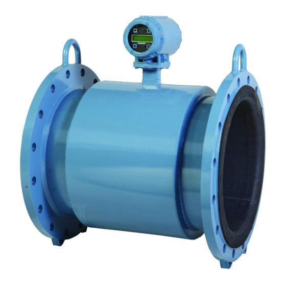
Reference Manual Introduction 00809-0300-4750, Rev CA March 2016 Section 1 Introduction System description ™ The Rosemount 8750W Magnetic Flowmeter System consists of a sensor and a transmitter. The sensor is installed in-line with the process piping; the transmitter can be remotely mounted or integrally mounted to the sensor. -
Page 14: Product Recycling/Disposal
Introduction 00809-0300-4750, Rev CA March 2016 Figure 1-4. Rosemount 8750W Cross Section The flow sensor contains two magnetic coils located on opposite sides of the sensor. Two electrodes, located perpendicular to the coils and opposite each other, make contact with the liquid. -
Page 15: Introduction
Reference Manual Quick Installation and Start-Up 00809-0300-4750, Rev CA March 2016 Section 2 Quick Installation and Start-Up Introduction ............. page 3 Safety messages . -
Page 16: Transmitter Symbols
To prevent ignition of flammable or combustible atmospheres, disconnect power before servicing circuits. Do not connect a Rosemount 8750W Transmitter to a non-Rosemount sensor that is located in an explosive atmosphere. Follow national, local, and plant standards to properly earth ground the ... -
Page 17: Pre-Installation
Only available with the Field Mount Transmitter. In most cases, it will not be necessary to change the setting of the hardware switches. If the switch settings need to be changed, follow the steps outlined in the Rosemount 8750W Reference Manual (see “Changing hardware switch settings”... -
Page 18: Mechanical Considerations
2.5.3 Mechanical considerations The mounting site for the Rosemount 8750W should provide enough room for secure mounting, easy access to conduit entries, full opening of the transmitter covers, and easy readability of the LOI screen if equipped. For remote mount transmitter installations, a mounting bracket is provided for use on a 2-in. - Page 19 Reference Manual Quick Installation and Start-Up 00809-0300-4750, Rev CA March 2016 Dimensional drawings Figure 2-1. Rosemount 8750W Remote Field Mount Transmitter 7.49 (189,8) 5.77 (146,4) 6.48 (164,6) 1.94 (49,3) 5.00 3.00 7.64 (127,0) (76,2) 8.86 (194,0) (225,1) 10.29 (261,3) 2.81 3.07...
- Page 20 Reference Manual Quick Installation and Start-Up 00809-0300-4750, Rev BA March 2016 Figure 2-3. Rosemount 8750W Wall Mount Transmitter with Standard Cover 9.01 4.31 (229) (109) 3.11 2.81 0.44 (79) (71) 12.02 (305) 11.15 (283) 2.96 (75) A. Ground lug -in. –14 NPT conduit connection (4 places) Dimensions in inches (millimeters).
-
Page 21: Electrical Considerations
March 2016 2.5.4 Electrical considerations Before making any electrical connections to the Rosemount 8750W, consider national, local and plant electrical installation requirements. Be sure to have the proper power supply, conduit, and other accessories necessary to comply with these standards. -
Page 22: Handling And Lifting
Reference Manual Quick Installation and Start-Up 00809-0300-4750, Rev BA March 2016 Handling and lifting Handle all parts carefully to prevent damage. Whenever possible, transport the system to the installation site in the original shipping container. PTFE-lined sensors are shipped with end covers that protect it from both ... -
Page 23: Mounting
Reference Manual Quick Installation and Start-Up 00809-0300-4750, Rev CA March 2016 Mounting 2.7.1 Upstream/downstream piping To ensure specified accuracy over widely varying process conditions, install the sensor with a minimum of five straight pipe diameters upstream and two pipe diameters downstream from the electrode plane (see Figure 2-6). -
Page 24: Sensor Location
Reference Manual Quick Installation and Start-Up 00809-0300-4750, Rev BA March 2016 Sensor location The sensor should be installed in a location that ensures it remains full during operation. Vertical installation with upward process fluid flow keeps the cross-sectional area full, regardless of flow rate. -
Page 25: Sensor Installation
Reference Manual Quick Installation and Start-Up 00809-0300-4750, Rev CA March 2016 Sensor installation 2.9.1 Flanged sensors Gaskets The sensor requires a gasket at each process connection. The gasket material must be compatible with the process fluid and operating conditions. Gaskets are required on each side of a grounding ring (see Figure 2-10). - Page 26 Reference Manual Quick Installation and Start-Up 00809-0300-4750, Rev BA March 2016 Suggested torque values by sensor line size and liner type are listed in Table 2-3 for ASME B16.5 flanges and Table 2-4 for EN flanges. Consult the factory if the flange rating of the sensor is not listed.
- Page 27 Reference Manual Quick Installation and Start-Up 00809-0300-4750, Rev CA March 2016 Table 2-3. Flange Bolt Torque and Load Specifications (ASME) Fluoropolymer liners Resilient liners Size code Line size Class 150 Class 300 Class 150 Class 300 (pound-feet) (pound-feet) (pound-feet) (pound-feet) 0.5-in.
- Page 28 Reference Manual Quick Installation and Start-Up 00809-0300-4750, Rev BA March 2016 Table 2-4. Flange Bolt Torque and Load Specifications (EN 1092-1) Fluoropolymer liners PN10 PN 16 V PN 25 PN 40 Size code Line size (Newton- (Newton- (Newton- (Newton- meter) meter) meter) meter)
-
Page 29: Process Reference Connection
Reference Manual Quick Installation and Start-Up 00809-0300-4750, Rev CA March 2016 Table 2-5. Flange Bolt Torque and Load Specifications Larger Line Sizes (AWWA C207) Fluoropolymer liners Size code Line size Class D Class E Class F (pound-feet) (pound-feet) (pound-feet) 30-in. (750 mm) 36-in. - Page 30 Reference Manual Quick Installation and Start-Up 00809-0300-4750, Rev BA March 2016 Table 2-7 to determine which process reference option to follow for proper installation. Table 2-7. Process Reference Installation Process reference options Grounding Reference Lining Type of pipe Grounding rings straps electrode protectors...
-
Page 31: Wiring The Transmitter
Reference Manual Quick Installation and Start-Up 00809-0300-4750, Rev CA March 2016 Figure 2-14. Grounding with Grounding Rings in Non-Conductive Pipe A. Grounding rings Figure 2-15. Grounding with Reference Electrode in Conductive Unlined Pipe Figure 2-16. Grounding for Line Sizes 10-in. and Larger 2.11 Wiring the transmitter This wiring section covers the wiring between the transmitter and sensor, the 4—20 mA... -
Page 32: Conduit Entries And Connections
Integral mount transmitters ordered with a sensor will be shipped assembled and wired at the factory using an interconnecting cable. (See Figure 2-18). Use only the interconnecting cable provided by Emerson Process Management. For replacement transmitters use the existing interconnecting cable from the original assembly. Replacement cables are available. Quick Installation and Start-Up... - Page 33 Figure 2-18. Interconnecting Cables Remote mount transmitters Cables kits are available as individual component cables or as a combination coil/electrode cable. Remote cables can be ordered direct from Emerson Process Management using the kit numbers shown in Table 2-8 Table 2-9.
- Page 34 Reference Manual Quick Installation and Start-Up 00809-0300-4750, Rev BA March 2016 Table 2-9. Combination Cable Kits Coil/Electrode cable (-20 °C to 80 °C) Cable kit number Description 08732-0065-2001 (feet) Kit, Combination cable, Standard 08732-0065-2002 (meters) 08732-0065-3001 (feet) Kit, Combination cable, Submersible (80 °C dry/60 °C Wet)(33 ft.
- Page 35 Reference Manual Quick Installation and Start-Up 00809-0300-4750, Rev CA March 2016 Figure 2-20. Combination Coil/Electrode Cable Cable Color number Blue Drain Reference Yellow White A. Electrode shield-drain B. Overlapping foil shield C. Outer jacket Cable preparation When preparing all wire connections, remove only the insulation required to fit the wire completely under the terminal connection.
-
Page 36: Rosemount 8750W Transmitter Terminal Block Connections
Reference Manual Quick Installation and Start-Up 00809-0300-4750, Rev BA March 2016 Shock Hazard Potential shock hazard across remote junction box terminals 1 and 2 (40V). Explosion Hazard Electrodes exposed to process. Use only compatible transmitter and approved installation practices. Figure 2-22. Remote Junction Box Views A. -
Page 37: Analog Output
Reference Manual Quick Installation and Start-Up 00809-0300-4750, Rev CA March 2016 Wall mount transmitter Open the lower cover of the transmitter to access the terminal block. See Figure 2-24 terminal identification or inside the cover for wiring terminal identification. To connect the pulse output and or discrete input/output, see “Connect pulse output”... - Page 38 Reference Manual Quick Installation and Start-Up 00809-0300-4750, Rev BA March 2016 Figure 2-25. Field Mount Transmitter Analog Wiring - Internal Power – 4-20mA + 4-20mA Note Terminal polarity for the analog output is reversed between internally and externally powered. External power The 4—20mA analog signal is passive and must be powered from an external power source.
- Page 39 Reference Manual Quick Installation and Start-Up 00809-0300-4750, Rev CA March 2016 Figure 2-27. Field Mount Transmitter Analog Loop Load Limitations Operating region 10.8 Power supply (Volts) = 31.25 (V — 10.8) = Power supply voltage (Volts) = Maximum loop resistance (Ohms) Wall mount transmitter The analog output signal is a 4—20mA current loop.
-
Page 40: Powering The Transmitter
Reference Manual Quick Installation and Start-Up 00809-0300-4750, Rev BA March 2016 Analog loop load limitations Maximum loop resistance is determined by the voltage level of the external power supply, as described in Figure 2-29. Figure 2-29. Wall Mount Transmitter Analog Loop Load Limitations 1000 Operating region... - Page 41 Reference Manual Quick Installation and Start-Up 00809-0300-4750, Rev CA March 2016 Figure 2-31. Wall Mount Transmitter DC Power Requirements Power supply (VDC) Figure 2-32. Field Mount Transmitter AC Power Requirements 0.26 0.24 0.22 0.20 0.18 0.16 0.14 0.12 0.10 Power supply (VAC) Power supply (VAC) Peak inrush is 35.7 A at 250 VAC supply, lasting approximately 1ms Inrush for other supply voltages can be estimated with:...
- Page 42 Disconnects Connect the device through an external disconnect or circuit breaker per national and local electrical code. Installation category The installation category for the Rosemount 8750W is OVERVOLTAGE CAT II. Quick Installation and Start-Up...
- Page 43 Reference Manual Quick Installation and Start-Up 00809-0300-4750, Rev CA March 2016 Overcurrent protection The Rosemount 8750W Transmitter requires overcurrent protection of the supply lines. Fuse rating and compatible fuses are shown in Table 2-10 Table 2-11. Table 2-10. Field Mount Transmitter Fuse Requirements...
-
Page 44: Field Mount Transmitter Cover Jam Screw
Reference Manual Quick Installation and Start-Up 00809-0300-4750, Rev BA March 2016 2.12 Field mount transmitter cover jam screw For flow meters shipped with a cover jam screw, the screw should be installed after the instrument has been wired and powered up. Follow these steps to install the cover jam screw: Verify the cover jam screw is completely threaded into the housing. - Page 45 Reference Manual Quick Installation and Start-Up 00809-0300-4750, Rev CA March 2016 Flow units (PV) Field Mount: Basic Setup, Flow Units, PV Units LOI menu path Wall Mount: UNITS 1, 3, 1 Traditional Fast Keys 2, 2, 1, 2 Device dashboard The flow units variable specifies the format in which the flow rate will be displayed.
- Page 46 Reference Manual Quick Installation and Start-Up 00809-0300-4750, Rev BA March 2016 Calibration number Field Mount: Basic Setup, Cal Number LOI menu path Wall Mount: TUBE CAL NO. 1, 3, 1 Traditional Fast Keys 2, 2, 1, 4, 1 Device dashboard The sensor calibration number is a 16-digit number generated at the Rosemount factory during flow calibration and is unique to each sensor and is located on the sensor tag.
- Page 47 Reference Manual Quick Installation and Start-Up 00809-0300-4750, Rev CA March 2016 Table 2-12. Available Flow Units Volumetric units Impgal/hr Impgal/day B42/sec (1 barrel = 42 gallons) B42/min (1 barrel = 42 gallons) B42/hr (1 barrel = 42 gallons) B42/day (1 barrel = 42 gallons) B31/sec (1 barrel = 31 gallons) B31/min (1 barrel = 31 gallons) B31/hr (1 barrel = 31 gallons)
- Page 48 Reference Manual Quick Installation and Start-Up 00809-0300-4750, Rev BA March 2016 Quick Installation and Start-Up...
-
Page 49: Introduction
Reference Manual Advanced Installation Details 00809-0300-4750, Rev CA March 2016 Section 3 Advanced Installation Details Introduction ............. page 37 Safety messages . -
Page 50: Transmitter Security
3.3.2 Transmitter security The security switch on the Rosemount 8750W allows the user to lock out any configuration changes attempted on the transmitter. No changes to the configuration are allowed when the switch is in the ON position. The flow rate indication and totalizer functions remain active at all times. - Page 51 Reference Manual Advanced Installation Details 00809-0300-4750, Rev CA March 2016 Identify the location of each switch (see Figure 3-1 Figure 3-2). Change the setting of the desired switches with a small, non-metallic tool. Replace the LOI if applicable, and the electronics compartment cover. If the cover has a cover jam screw, this must be tightened to comply with installation requirements.
-
Page 52: Additional Loops
Reference Manual Advanced Installation Details 00809-0300-4750, Rev CA March 2016 Additional loops There are three additional loop connections available on the 8750W Transmitter: Pulse output — used for external or remote totalization. Channel 1 can be configured as discrete input or discrete output. ... - Page 53 Reference Manual Advanced Installation Details 00809-0300-4750, Rev CA March 2016 Figure 3-3. Field Mount Transmitter — Maximum Frequency vs. Cable Length 10000 < 500 Ω 1 KΩ 2.5 KΩ 5 KΩ 1000 10 KΩ 1000 Cable length (feet) Complete the following steps to connect an external power supply. Ensure the power source and connecting cable meet the requirements outlined previously.
- Page 54 Reference Manual Advanced Installation Details 00809-0300-4750, Rev CA March 2016 Figure 3-4. Field Mount Transmitter — Connecting Electromechanical Totalizer/Counter with External Power Supply A. Schematic showing FET between terminal 3 and 4 B. 5—24 V DC power supply C. Electro-mechanical counter Note Total loop impedance must be sufficient to keep loop current below maximum rating.
- Page 55 Reference Manual Advanced Installation Details 00809-0300-4750, Rev CA March 2016 Internal When the pulse switch is set to internal, the pulse loop will be powered from the transmitter. Supply voltage from the transmitter can be up to 12 VDC. Refer to Figure 3-6 and connect the transmitter directly to the counter.
-
Page 56: Connect Discrete Output
Reference Manual Advanced Installation Details 00809-0300-4750, Rev CA March 2016 Figure 3-7. Wall Mount Transmitter — Connecting to an Electromechanical Totalizer/Counter A. Electromechanical counter B. 5–28 VDC power supply Figure 3-8. Wall Mount Transmitter — Connecting to an Electronic Totalizer/Counter A. - Page 57 Reference Manual Advanced Installation Details 00809-0300-4750, Rev CA March 2016 For discrete output control, connect the power source and control relay to the transmitter. To connect external power for discrete output control, complete the following steps: Ensure the power source and connecting cable meet the requirements outlined previously.
-
Page 58: Connect Discrete Input
Reference Manual Advanced Installation Details 00809-0300-4750, Rev CA March 2016 Figure 3-10. Wall Mount Transmitter — Connect Discrete Output to Relay or Control System Input A. Digital output 1 B. Digital output 2 C. 5–28 VDC power supply Note Total loop impedance must be sufficient to keep loop current below maximum rating. A resistor can be added in the loop to raise impedance. - Page 59 Reference Manual Advanced Installation Details 00809-0300-4750, Rev CA March 2016 Figure 3-11. Field Mount Transmitter – Connect Discrete Input A. Relay contact or control system output B. 5-28 V DC power supply Figure 3-12. Discrete Input Operating Range Digital input operating range 12.5 Series Resistance Ωin + Ωext (Kohms) Figure 3-13.
-
Page 60: Process Reference Connection
Reference Manual Advanced Installation Details 00809-0300-4750, Rev CA March 2016 Process reference connection Establishing a process reference for the sensor is one of the most important details of sensor installation. Proper process reference creates the lowest noise environment for the transmitter to make a stable reading. -
Page 61: Introduction
For detailed LOI configuration refer to Section 5: Advanced Configuration Functionality. Field mount transmitter Loi The optional LOI provides a communications center for the Rosemount 8750W. The LOI allows an operator to: Change transmitter configuration View flow and totalizer values ... -
Page 62: Basic Features
Reference Manual Operation 00809-0300-4750, Rev CA March 2016 4.2.1 Basic features The basic features of the LOI include a display window and four navigational arrow keys (see Figure 4-1). To activate the LOI, select the DOWN arrow two times. Select the UP, DOWN, LEFT, and RIGHT arrows to navigate the menu structure. -
Page 63: Data Entry Examples
Reference Manual Operation 00809-0300-4750, Rev CA March 2016 4.2.3 Data entry examples Select the DOWN arrow key twice to access the menu structures shown in Figure 4-2 Figure 4-3. Use the arrow keys to navigate to the desired parameters to review/change. Parameter values are classified as table values or select values. -
Page 64: Totalizer Functionality
4.2.5 Display lock The Rosemount 8750W Field Mount Transmitter has display lock functionality to prevent unintentional configuration changes. The display can be locked manually or configured to automatically lock after a set period of time. -
Page 65: Diagnostic Messages
Reference Manual Operation 00809-0300-4750, Rev CA March 2016 Auto display lock Select the DOWN arrow key twice to access the menu. See Table 4-2. Using the arrow keys, select LOI config from the Detailed Setup menu. Select DOWN arrow to highlight disp auto lock and press the RIGHT arrow to enter the menu. - Page 66 Reference Manual Operation 00809-0300-4750, Rev CA March 2016 Figure 4-2. Field Mount Transmitter LOI Menu Tree (Diagnostics and Basic Setup) Diagnostics Diag Controls Empty Pipe Coils Basic Diag Basic Setup Process Noise Electrodes Advanced Diag Detailed Setup Ground/Wiring Transmitter Variables Elec Coating Analog Output Trims...
- Page 67 Reference Manual Operation 00809-0300-4750, Rev CA March 2016 Figure 4-3. Field Mount Transmitter LOI Menu Tree (Detailed Setup) Diagnostics Basic Setup Detailed Setup More Params Coil Frequency Output Config Proc Density LOI Config PV USL PV URV Sig Processing PV LSL Empty Pipe PV LRV Device Info...
-
Page 68: Wall Mount Transmitter Local Operator Interface (Loi)
Reference Manual Operation 00809-0300-4750, Rev CA March 2016 Wall mount transmitter LOI 4.3.1 Basic features The basic features of the LOI include display control, totalizer, data entry, and transmitter parameters. These features provide control of all transmitter functions, see Figure 4-4. -
Page 69: Data Entry Examples
Reference Manual Operation 00809-0300-4750, Rev CA March 2016 Select INCR. to change the highlighted value. For numerical data, INCR. toggle through the digits 0–9, decimal point, and dash. For alphabetical data, toggle through the letters of the alphabet A–Z, digits 0– ... -
Page 70: Totalizer Functionality
Reference Manual Operation 00809-0300-4750, Rev CA March 2016 4.3.4 Totalizer functionality Start totalizer To start the totalizer, select the TOTALIZE button to bring up the totalizer screen. Select START/STOP to begin totalization. A flashing letter “T” on the LOI indicates that totalizer is activated. - Page 71 Reference Manual Operation 00809-0300-4750, Rev CA March 2016 Figure 4-5. Wall Mount Transmitter LOI Menu Tree Operation...
-
Page 72: Field Communicator Interface
Reference Manual Operation 00809-0300-4750, Rev CA March 2016 Field Communicator interface The transmitter can be configured with a Field Communicator using HART Protocol gaining access to the software functions, transmitter configurations, and diagnostic settings. Refer to the Field Communicator Manual for detailed instructions on how to connect to the device. -
Page 73: March
Reference Manual Operation 00809-0300-4750, Rev CA March 2016 The device dashboard interface Fast Keys are located in Table 4-2 on page 70. The corresponding menu tree is located Figure 4-10 on page 80 Figure 4-11 on page Table 4-1. Traditional Field Communicator Fast Keys Function Traditional Fast Keys Process variables... - Page 74 Reference Manual Operation 00809-0300-4750, Rev CA March 2016 Table 4-1. Traditional Field Communicator Fast Keys Function Traditional Fast Keys Other 1, 2, 2, 2, 4 1, 2, 2, 2, 5 Pulse Output Loop Test 1, 2, 2, 3 Tune Empty Pipe 1, 2, 2, 4 EP Value 1, 2, 2, 4, 1...
- Page 75 Reference Manual Operation 00809-0300-4750, Rev CA March 2016 Table 4-1. Traditional Field Communicator Fast Keys Function Traditional Fast Keys Manual Results 1, 2, 3, 2, 2, 1 Test Condition 1, 2, 3, 2, 2, 1, 1 Test Criteria 1, 2, 3, 2, 2, 1, 2 8714i Test Result 1, 2, 3, 2, 2, 1, 3 Simulated Velocity...
- Page 76 Reference Manual Operation 00809-0300-4750, Rev CA March 2016 Table 4-1. Traditional Field Communicator Fast Keys Function Traditional Fast Keys Measurements 1, 2, 3, 2, 5 Manual Measurements 1, 2, 3, 2, 5, 1 Coil Resistance 1, 2, 3, 2, 5, 1, 1 Coil Signature 1, 2, 3, 2, 5, 1, 2 Electrode Resistance...
- Page 77 Reference Manual Operation 00809-0300-4750, Rev CA March 2016 Table 4-1. Traditional Field Communicator Fast Keys Function Traditional Fast Keys Manual Results 1, 2, 4, 8, 1 Test Condition 1, 2, 4, 8, 1, 1 Test Criteria 1, 2, 4, 8, 1, 2 8714i Test Result 1, 2, 4, 8, 1, 3 Simulated Velocity...
- Page 78 Reference Manual Operation 00809-0300-4750, Rev CA March 2016 Table 4-1. Traditional Field Communicator Fast Keys Function Traditional Fast Keys PV Units 1, 3, 2, 1 Special Units 1, 3, 2, 2 Volume Unit 1, 3, 2, 2, 1 Base Volume Unit 1, 3, 2, 2, 2 Conversion Number 1, 3, 2, 2, 3...
- Page 79 Reference Manual Operation 00809-0300-4750, Rev CA March 2016 Table 4-1. Traditional Field Communicator Fast Keys Function Traditional Fast Keys Electrode Coat Limit 2 1, 4, 2, 1, 9, 6 -- Totalizer Limit 1 1, 4, 2, 1, 9, 7 -- Flow Limit 1 1, 4, 2, 1, 9, 8 -- Flow Limit 2...
- Page 80 Reference Manual Operation 00809-0300-4750, Rev CA March 2016 Table 4-1. Traditional Field Communicator Fast Keys Function Traditional Fast Keys Total Low Limit 1, 4, 2, 3, 5, 4 Total Limit Hysteresis 1, 4, 2, 3, 5, 5 Diagnostic Status Alert 1, 4, 2, 3, 6 Electronics Failure 1, 4, 2, 3, 6, --...
- Page 81 Reference Manual Operation 00809-0300-4750, Rev CA March 2016 Table 4-1. Traditional Field Communicator Fast Keys Function Traditional Fast Keys QV is 1, 4, 2, 7, 1, 4 Poll Address 1, 4, 2, 7, 2 Num Req Preams 1, 4, 2, 7, 3 Num Resp Preams 1, 4, 2, 7, 4 Burst Mode...
- Page 82 Reference Manual Operation 00809-0300-4750, Rev CA March 2016 Table 4-1. Traditional Field Communicator Fast Keys Function Traditional Fast Keys Sensor Tag 1, 4, 6, 8 Write protect 1, 4, 6, 9 Revision No. 1, 4, 6, 10 Universal Rev 1, 4, 6, 10, 1-- Transmitter Rev 1, 4, 6, 10, 2-- Software Rev...
- Page 83 Reference Manual Operation 00809-0300-4750, Rev CA March 2016 Table 4-2. Device Dashboard Fast Keys Function Fast Keys Message 1, 8, 1, 8 Universal Revision 1, 8, 2, 1 Device Revision 1, 8, 2, 2 Software Revision 1, 8, 2, 3 Hardware Revision 1, 8, 2, 4 DD Revision...
- Page 84 Reference Manual Operation 00809-0300-4750, Rev CA March 2016 Table 4-2. Device Dashboard Fast Keys Function Fast Keys Discrete Input/Output 2, 1, 2, 3 Totalizer 2, 1, 2, 4 Reverse Flow 2, 1, 2, 5 Burst Mode 2, 1, 2, 7 Variable Mapping 2, 1, 2, 8 Diagnostics...
- Page 85 Reference Manual Operation 00809-0300-4750, Rev CA March 2016 Table 4-2. Device Dashboard Fast Keys Function Fast Keys Polling Address 2, 2, 3, 1, 1 Burst Option 2, 2, 3, 1, 3 Primary Variable 2, 2, 3, 2, 1 Secondary Variable 2, 2, 3, 2, 2 Third Variable 2, 2, 3, 2, 3...
- Page 86 Reference Manual Operation 00809-0300-4750, Rev CA March 2016 Table 4-2. Device Dashboard Fast Keys Function Fast Keys Electrode Coating Level 2 Limit 2, 2, 5, 6, 3 Electrode Coating Maximum Value 2, 2, 5, 6, 4 Reset Maximum Electrode Coating Value 2, 2, 5, 6, 5 Diagnostic Analog Alarm 2, 2, 5, 9...
- Page 87 Reference Manual Operation 00809-0300-4750, Rev CA March 2016 Table 4-2. Device Dashboard Fast Keys Function Fast Keys Flow Limit 1 2, 3, 3 Flow Limit 2 2, 3, 4 Totalizer Limit 2, 3, 5 Analog Alarm 2, 3, 6 Discrete Output Alert 2, 3, 7 Calibration 2, 4...
- Page 88 Reference Manual Operation 00809-0300-4750, Rev CA March 2016 Table 4-2. Device Dashboard Fast Keys Function Fast Keys Continuous Simulated Velocity 3, 2, 4, 3, 1 Continuous Actual Velocity 3, 2, 4, 3, 2 Continuous Velocity Deviation 3, 2, 4, 3, 3 Continuous Analog Output Measurements 3, 2, 4, 4 Continuous Expected mA Value...
- Page 89 Reference Manual Operation 00809-0300-4750, Rev CA March 2016 Table 4-2. Device Dashboard Fast Keys Function Fast Keys Manual Transmitter Deviation 3, 4, 1, 5, 3, 3 Manual Transmitter Test Result 3, 4, 1, 5, 3, 4 Manual Test Conditions 3, 4, 1, 5, 4, 1 Manual Overall Test Result 3, 4, 1, 5, 4, 2 Continuous Meter Verification Limit...
- Page 90 Reference Manual Operation 00809-0300-4750, Rev CA March 2016 Figure 4-8. Field Communicator Traditional Menu Tree (Basic Setup and Detailed Setup) Home 1 Device Setup Device Setup 2 PV 1 Process Variables 3 PV AO 2 Diagnostics Basic Setup 4 PV LRV 3 Basic Setup 1 Tag 5 PV URV...
- Page 91 Reference Manual Operation 00809-0300-4750, Rev CA March 2016 Figure 4-9. Field Communicator Traditional Menu Tree (Process Variables and Diagnostics) Main Menu Process Variables Totalizer Setup 1 Device Setup 1 PV 1 Totalizer Units 2 PV 2 PV % rnge 2 Gross Total 3 PV Loop Current 3 PV Loop Current 3 Net Total...
- Page 92 Reference Manual Operation 00809-0300-4750, Rev CA March 2016 Figure 4-10. Field Communicator Dashboard Menu Tree (Overview and Configuring Guided/Manual Setup) Operation...
- Page 93 Reference Manual Operation 00809-0300-4750, Rev CA March 2016 Figure 4-11. Field Communicator Dashboard Menu Tree (Configuring Alert Setup and Service Tools) Operation...
-
Page 94: Process Variables
Reference Manual Operation 00809-0300-4750, Rev CA March 2016 Process variables LOI menu path 1, 1 Traditional Fast Keys Device dashboard Process variables are available through the Field Communicator or AMS software suite. These variables display flow in several ways that reflect your needs and the configuration of your flowmeter. -
Page 95: Pv - Analog Output
Reference Manual Operation 00809-0300-4750, Rev CA March 2016 4.5.3 PV - Analog output LOI menu path 1, 1, 3 Traditional Fast Keys Device dashboard The PV analog output displays the mA output of the transmitter corresponding to the measured flow rate. 4.5.4 Pulse output LOI menu path... - Page 96 Reference Manual Operation 00809-0300-4750, Rev CA March 2016 Operation...
-
Page 97: Introduction
Reference Manual Advanced Configuration Functionality 00809-0300-4750, Rev CA March 2016 Section 5 Advanced Configuration Functionality Introduction ............page 85 Configure outputs . - Page 98 Reference Manual Advanced Configuration Functionality 00809-0300-4750, Rev CA March 2016 Upper range value Field Mount: Detailed Setup, Output Config, Analog, PV URV LOI menu path Wall Mount: ANALOG OUTPUT RANGE 1, 4, 2, 1 Traditional Fast Keys 2, 2, 2, 1, 4 Device dashboard The upper range value (URV) sets the 20 mA point for the analog output.
- Page 99 Reference Manual Advanced Configuration Functionality 00809-0300-4750, Rev CA March 2016 Alarm level Field Mount: Detailed Setup, Output Config, Analog, Alarm Level LOI menu path Wall Mount: AUX. FUNCTION 1, 4, 2, 1, 8 or 1, 4, 2, 6 Traditional Fast Keys 2, 2, 9, 5, 2 Device dashboard The alarm level configuration will drive the transmitter to preset values if an alarm occurs.
-
Page 100: Pulse Output
Field Mount: Detailed Setup, Output Config, Pulse LOI menu path Wall Mount: N/A 1, 4, 2, 2 Traditional Fast Keys 2, 2, 2, 2 Device dashboard Under this function the pulse output of the Rosemount 8750W can be configured. Advanced Configuration Functionality... - Page 101 11,000Hz. For example, if you want the Rosemount 8750W to pulse every time 0.01 gallons pass through the sensor, and the flow rate is 10,000 gal/min, you will exceed the 10,000 Hz full-scale limit:...
- Page 102 Reference Manual Advanced Configuration Functionality 00809-0300-4750, Rev CA March 2016 The width, or duration, of the pulse can be adjusted to match the requirements of different counters or controllers (see Figure 5-1). These are typically lower frequency applications (< 1000 Hz). The transmitter will accept values from 0.1 ms to 650 ms. For frequencies higher than 1000 Hz, it is recommended to set the pulse mode to 50% duty cycle by setting the pulse mode to frequency output.
- Page 103 Reference Manual Advanced Configuration Functionality 00809-0300-4750, Rev CA March 2016 10 000 gpm -------------------------------------------------------- - Pulse Scaling = × ---------- - 10 000Hz -------------- - Pulse Scaling = 0.0167 pulse 1 pulse = 0.0167 gal Note Changes to pulse width are only required when there is a minimum pulse width required for external counters, relays, etc.
-
Page 104: Totalizer
Reference Manual Advanced Configuration Functionality 00809-0300-4750, Rev CA March 2016 Pulse mode Field Mount: Detailed Setup, Output Config, Pulse, Pulse Mode LOI menu path Wall Mount: N/A 1, 4, 2, 2, 3 Traditional Fast Keys 2, 2, 2, 2, 2 Device dashboard The pulse mode configures the frequency output of the pulse. - Page 105 Reference Manual Advanced Configuration Functionality 00809-0300-4750, Rev CA March 2016 Totalizer display Field Mount: Detailed Setup, Output Config, Totalizer Setup, Total Display LOI menu path Wall Mount: AUX. FUNCTION 1, 4, 3, 3 Traditional Fast Keys 2, 2, 1, 5, 3 Device dashboard The totalizer screen can be configured to display the net and gross totals or the forward and reverse totals.
-
Page 106: Discrete Input/Output
Reference Manual Advanced Configuration Functionality 00809-0300-4750, Rev CA March 2016 Note The totalizer value is stored in the non-volatile memory of the electronics every three seconds. If power to the transmitter is interrupted, the totalizer value will start at the last saved value when power is reapplied. - Page 107 Reference Manual Advanced Configuration Functionality 00809-0300-4750, Rev CA March 2016 DI/O 1 control Field Mount: Detailed Setup, Output Config, DI/DO Config, DI/O 1, DI/O Control LOI menu path Wall Mount: AUX. FUNCTION 1, 4, 2, 3, 1, 1 Traditional Fast Keys 2, 2, 4, 1, 1 Device dashboard This parameter configures the auxiliary output channel 1.
- Page 108 Reference Manual Advanced Configuration Functionality 00809-0300-4750, Rev CA March 2016 Flow limit (1 and 2) Flow 1 Flow 2 Field Mount: Detailed Setup, Output Field Mount: Detailed Setup, Output Config, DI/DO Config, Config, DI/DO Config, LOI menu path Flow Limit 1 Flow Limit 2 Wall Mount: AUX.
- Page 109 Reference Manual Advanced Configuration Functionality 00809-0300-4750, Rev CA March 2016 Mode Flow 1 Flow 2 Field Mount: Detailed Setup, Out- Field Mount: Detailed Setup, Out- put Config, DI/DO put Config, DI/DO Config, Flow Limit 1, Config, Flow Limit 2, LOI menu path Mode 1 Mode 2 Wall Mount: AUX.
- Page 110 Reference Manual Advanced Configuration Functionality 00809-0300-4750, Rev CA March 2016 Low limit Flow 1 Flow 2 Field Mount: Detailed Setup, Field Mount: Detailed Setup, Output Config, Output Config, DI/DO Config, Flow DI/DO Config, Flow LOI menu path Limit 1, Low Limit 1 Limit 2, Low Limit 2 Wall Mount: AUX.
- Page 111 Reference Manual Advanced Configuration Functionality 00809-0300-4750, Rev CA March 2016 Total limit Field Mount: Detailed Setup, Output Config, Totalizer, Total Limit LOI menu path Wall Mount: AUX. FUNCTION 1, 4, 2, 3, 5 Traditional Fast Keys 2, 2, 4, 5 Device dashboard Configure the parameters that will determine the criteria for activating a HART alert if the measured net total falls within a set of configured criteria.
- Page 112 Reference Manual Advanced Configuration Functionality 00809-0300-4750, Rev CA March 2016 Total high limit Field Mount: Detailed Setup, Output Config, Totalizer, Total Limit, Tot Hi Limit LOI menu path Wall Mount: AUX. FUNCTION 1, 4, 2, 3, 5, 3 Traditional Fast Keys 2, 2, 4, 5, 1 Device dashboard Set the net total value that corresponds to the high limit set point for the total high limit...
-
Page 113: Configure Hart
1. Only available on Field Mount Transmitter. Configure HART The Rosemount 8750W has four HART variables available as outputs. The variables can be configured for dynamic readings including flow, total, and diagnostic values. The HART output can also be configured for burst mode or multi-drop communication if required. - Page 114 Reference Manual Advanced Configuration Functionality 00809-0300-4750, Rev CA March 2016 Secondary variable (SV) Field Mount: Detailed Setup, Output Config, Hart, Variable Map, SV LOI menu path Wall Mount: N/A 1, 4, 2, 7, 1, 2 Traditional Fast Keys 2, 2, 3, 2, 2 Device dashboard The secondary variable maps the second variable of the transmitter.
-
Page 115: Poll Address
2, 2, 3, 1, 2 Device dashboard The Rosemount 8750W includes a burst mode function that can be enabled to broadcast the primary variable or all dynamic variables approximately three to four times per second. Burst mode is a specialized function used in very specific applications. The burst mode function enables you to select the variables that are broadcast while in the burst mode. -
Page 116: Configure Loi
Wall Mount: N/A 1, 4, 2, 7, 3 Traditional Fast Keys Device dashboard Request preambles is the number of preambles required by the Rosemount 8750W for HART communications. Response preambles Field Mount: Detailed Setup, Output Config, HART, Resp Preams LOI menu path... - Page 117 Reference Manual Advanced Configuration Functionality 00809-0300-4750, Rev CA March 2016 Flow display Field Mount: Detailed Setup, LOI Config, Flow Display LOI menu path Wall Mount: AUX. FUNCTION 1, 4, 3, 2 Traditional Fast Keys 2, 2, 1, 5, 2 Device dashboard Use flow display to configure the parameters that will appear on the LOI flowrate screen.
-
Page 118: Additional Parameters
Reference Manual Advanced Configuration Functionality 00809-0300-4750, Rev CA March 2016 LOI error mask Field Mount: Detailed Setup, LOI Config, LOI Err Mask LOI menu path Wall Mount: N/A Traditional Fast Keys Device dashboard Use LOI error mask to turn off the analog output power error message (AO No Power). This may be desired if the analog output is not being used. -
Page 119: Process Density
Reference Manual Advanced Configuration Functionality 00809-0300-4750, Rev CA March 2016 5.4.2 Process density Field Mount: Detailed Setup, More Params, Proc Density LOI menu path Wall Mount: AUX. FUNCTION 1,4,3,1 Traditional Fast Keys 2,2,8,2 Device dashboard Use the process density value to convert from a volumetric flow rate to a mass flow rate using the following equation: Qm = Qv x p Where:... -
Page 120: Pv Damping
Traditional Fast Keys 2, 2, 8, 6 Device dashboard The Rosemount 8750W contains several advanced functions that can be used to stabilize erratic outputs caused by process noise. The signal processing menu contains this functionality. If the 37 Hz coil drive mode has been set, and the output is still unstable, the damping and signal processing function should be used. - Page 121 2, 2, 8, 6, 1 Device dashboard DSP can be turned on or off. When on is selected, the Rosemount 8750W output is derived using a running average of the individual flow inputs. DSP is a software algorithm that examines the quality of the electrode signal against user-specified tolerances. This average is updated at the rate of 10 samples per second with a coil drive frequency of 5 Hz, and 75 samples per second with a coil drive frequency of 37 Hz.
-
Page 122: Configure Special Units
10 seconds. In some cases this may be unacceptable. By setting the time limit, you can force the Rosemount 8750W to clear the value of the running average and re-establish the output and average at the new flow rate once the time limit has elapsed. This parameter limits the response time added to the loop. -
Page 123: Base Time Unit
The Field Communicator will display a special units designator as the units format for your primary variable. The actual special units setting you define will not appear. Four characters are available to store the new units designation. The Rosemount 8750W LOI will display the four character designation as configured. - Page 124 Reference Manual Advanced Configuration Functionality 00809-0300-4750, Rev CA March 2016 Advanced Configuration Functionality...
-
Page 125: Introduction
Reference Manual Advanced Diagnostics Configuration 00809-0300-4750, Rev CA March 2016 Section 6 Advanced Diagnostics Configuration Introduction ............page 113 Licensing and enabling . -
Page 126: Licensing And Enabling
See the detailed procedures below for entering the license key and enabling the advanced diagnostics. To obtain a permanent or trial ™ license key, contact your local Emerson Process Management representative. Trial license is only available on the Field Mount Transmitter. -
Page 127: Licensing The Rosemount 8750W Diagnostics
Advanced Diagnostics Configuration 00809-0300-4750, Rev CA March 2016 6.2.1 Licensing the Rosemount 8750W diagnostics For licensing the advanced diagnostics, follow the steps below. Power up the transmitter. Verify the software version is 5.4.4 software or later Field Mount: Detailed Setup, Device Info, Revision Num LOI menu path Wall Mount: AUX. -
Page 128: Tunable Empty Pipe Parameters
Reference Manual Advanced Diagnostics Configuration 00809-0300-4750, Rev CA March 2016 Turning empty pipe on/off Field Mount: Diagnostics, Diag Controls, Empty Pipe LOI menu path Wall Mount: AUX. FUNCTION 1, 2, 1, 1 Traditional Fast Keys 2, 2, 5, 1, 1 Device dashboard The tunable empty pipe detection diagnostic can be turned on or off as required by the application. -
Page 129: Optimizing Tunable Empty Pipe
Example: Set the counts to 10 Electronics temperature The Rosemount 8750W continuously monitors the temperature of the internal electronics. If the measured electronics temperature exceeds the operating limits of –40 to 140 °F (–40 to 60 °C) the transmitter will go into alarm and generate an alert. -
Page 130: Turning Electronics Temperature On/Off
Reference Manual Advanced Diagnostics Configuration 00809-0300-4750, Rev CA March 2016 6.4.1 Turning electronics temperature on/off Field Mount: Diagnostics, Diag Controls, Elect Temp LOI menu path Wall Mount: AUX. FUNCTION 1, 2, 1, 1, -- Traditional Fast Keys 2, 2, 5, 1, 4 Device dashboard This item is in a list format without numeric labels. -
Page 131: Turning Ground/Wiring Fault On/Off
Reference Manual Advanced Diagnostics Configuration 00809-0300-4750, Rev CA March 2016 6.5.1 Turning ground/wiring fault on/off Field Mount: Diagnostics, Diag Controls, Ground/Wiring LOI menu path Wall Mount: AUX. FUNCTION 1, 2, 1, 1, -- Traditional Fast Keys 2, 2, 5, 1, 3 Device dashboard This item is in a list format without numeric labels. -
Page 132: Turning High Process Noise On/Off
Reference Manual Advanced Diagnostics Configuration 00809-0300-4750, Rev CA March 2016 6.6.1 Turning high process noise on/off Field Mount: Diagnostics, Diag Controls, Process Noise LOI menu path Wall Mount: AUX. FUNCTION 1, 2, 1, 1, -- Traditional Fast Keys 2, 2, 5, 1, 2 Device dashboard 1. -
Page 133: Coated Electrode Detection
Reference Manual Advanced Diagnostics Configuration 00809-0300-4750, Rev CA March 2016 Coated electrode detection The coated electrode detection diagnostic provides a means of monitoring insulating coating buildup on the measurement electrodes. If coating is not detected, buildup over time can lead to a compromised flow measurement. This diagnostic can detect if the electrode is coated and if the amount of coating is affecting the flow measurement. - Page 134 Reference Manual Advanced Diagnostics Configuration 00809-0300-4750, Rev CA March 2016 Electrode coating (EC) level 1 limit Field Mount: Diagnostics, Advanced Diag, Elec Coat, EC Limit 1 LOI menu path Wall Mount: N/A 1, 2, 3, 1, 2 Traditional Fast Keys 2, 2, 5, 6, 2 Device dashboard Set the criteria for the electrode coating limit 1 which indicates when coating is starting to...
-
Page 135: 4-20 Ma Loop Verification
Reference Manual Advanced Diagnostics Configuration 00809-0300-4750, Rev CA March 2016 4-20 mA loop verification The 4-20 mA loop verification diagnostic provides a means of verifying the analog output loop is functioning properly. This is a manually initiated diagnostic test. This diagnostic checks the integrity of the analog loop and provides a health status of the circuit. -
Page 136: Smart™ Meter Verification
Reference Manual Advanced Diagnostics Configuration 00809-0300-4750, Rev CA March 2016 4 mA measurement LOI menu path Traditional Fast Keys 3, 4, 3, 2 Device dashboard Shows the measured value of the 4 mA loop verification test. 12 mA measurement LOI menu path Traditional Fast Keys 3, 4, 3, 3 Device dashboard... -
Page 137: Sensor Baseline (Signature) Parameters
Reference Manual Advanced Diagnostics Configuration 00809-0300-4750, Rev CA March 2016 provides a review of the transmitter and sensor's critical parameters as a means to document verification of calibration. The results of this diagnostic provide the deviation amount from expected values and a pass/fail summary against user-defined criteria for the application and conditions. -
Page 138: Establishing The Sensor Baseline (Signature)
Reference Manual Advanced Diagnostics Configuration 00809-0300-4750, Rev CA March 2016 Electrode circuit resistance Field Mount: Diagnostics, Advanced Diag, Meter Verify, Sensr Baseline, Values, Electrode Res LOI menu path Wall Mount: XMTR INFO 1, 2, 3, 2, 3, 1, 3 Traditional Fast Keys 2, 2, 6, 1, 3 Device dashboard The electrode circuit resistance is a measurement of the electrode circuit health. -
Page 139: Smart Meter Verification Test Criteria
Reference Manual Advanced Diagnostics Configuration 00809-0300-4750, Rev CA March 2016 6.9.3 SMART Meter Verification test criteria The SMART Meter Verification diagnostic provides the ability to customize the test criteria to which the verification must be tested. The test criteria can be set for each of the flow conditions discussed above. -
Page 140: Run Manual Smart Meter Verification
Reference Manual Advanced Diagnostics Configuration 00809-0300-4750, Rev CA March 2016 Continuous limit Field Mount: Diagnostics, Advanced Diag, Meter Verify, Test Criteria, Continual LOI menu path Wall Mount: N/A 1, 2, 3, 2, 4, 4 Traditional Fast Keys 2, 2, 6, 4, 1 Device dashboard Set the test criteria for the continuous SMART Meter Verification diagnostic. -
Page 141: Test Scope
Reference Manual Advanced Diagnostics Configuration 00809-0300-4750, Rev CA March 2016 6.10.2 Test scope The manually initiated SMART Meter Verification test can be used to verify the entire flowmeter installation or individual parts such as the transmitter or sensor. This parameter is set at the time that the SMART Meter Verification test is manually initiated. - Page 142 Reference Manual Advanced Diagnostics Configuration 00809-0300-4750, Rev CA March 2016 Coils Field Mount: Diagnostics, Diag Controls, Cont Meter Ver, Coils LOI menu path Wall Mount: N/A 1, 2, 1, 3, 1 Traditional Fast Keys 2, 2, 6, 4, 2, 1 Device dashboard Continuously monitor the sensor coil circuit by enabling this continuous SMART Meter Verification parameter.
-
Page 143: Smart Meter Verification Test Results
Reference Manual Advanced Diagnostics Configuration 00809-0300-4750, Rev CA March 2016 6.12 SMART Meter Verification test results If the SMART Meter Verification test is manually initiated, the transmitter will make several measurements to verify the transmitter calibration, sensor calibration, coil circuit health, and electrode circuits health. - Page 144 Reference Manual Advanced Diagnostics Configuration 00809-0300-4750, Rev CA March 2016 Table 6-2. Manual Smart Meter Verification Test Result Parameters Field mount LOI menu path Device Parameter (Diagnostics, Variables, MV Results, Traditional Dashboard Manual Results) Fast Keys Fast Keys Test Condition Test Condition 1, 2, 3, 2, 2, 1, 1 3, 4, 1, 5, 4, 1...
-
Page 145: Smart Meter Verification Measurements
Reference Manual Advanced Diagnostics Configuration 00809-0300-4750, Rev CA March 2016 6.13 SMART Meter Verification measurements The SMART Meter Verification test will make measurements of the coil resistance, coil signature, and electrode resistance and compare these values to the values taken during the sensor signature process to determine the sensor calibration deviation, the coil circuit health, and the electrode circuit health. - Page 146 Reference Manual Advanced Diagnostics Configuration 00809-0300-4750, Rev CA March 2016 Electrode circuit resistance Manual Continuous Field Mount: Diagnostics, Advanced Field Mount: Diagnostics, Advanced Diag, Meter Verify, Diag, Meter Verify, Measurements, Measurements, LOI menu path Manual Measure, Continual Meas, Electrode Res Electrode Res Wall Mount: XMTR INFO Wall Mount: N/A...
- Page 147 Reference Manual Advanced Diagnostics Configuration 00809-0300-4750, Rev CA March 2016 4-20 mA expected value Manual Continuous Field Mount: Diagnostics, Advanced Field Mount: Diagnostics, Advanced Diag, 4-20 mA Verify, Diag, Meter Verify, View Results Measurements, LOI menu path Continual Meas, 4-20 mA Expect Wall Mount: N/A Wall Mount: N/A...
-
Page 148: Optimizing The Smart Meter Verification
Reference Manual Advanced Diagnostics Configuration 00809-0300-4750, Rev CA March 2016 6.14 Optimizing the SMART Meter Verification The SMART Meter Verification diagnostic can be optimized by setting the test criteria to the desired levels necessary to meet the compliance requirements of the application. The following examples below will provide some guidance on how to set these levels. -
Page 149: Calibration Verification Report
Reference Manual Advanced Diagnostics Configuration 00809-0300-4750, Rev CA March 2016 6.15 Calibration Verification Report Calibration verification report parameters User Name:_________________________________ Calibration Conditions: Internal External Tag Number: ________________________________ Test Conditions: Flowing No Flow, Full Pipe Empty Pipe Flowmeter information and configuration Software Tag: _______________________________ PV URV (20 mA scale):______________________________________________... - Page 150 Reference Manual Advanced Diagnostics Configuration 00809-0300-4750, Rev CA March 2016 Advanced Diagnostics Configuration...
-
Page 151: Introduction
(37 Hz vs. 5 Hz) to isolate the flow signal from the process noise, the Rosemount 8750W microprocessor has digital signal processing capable of rejecting the noise specific to the application. This section explains the different types of process noise, provides instructions for optimizing the flow reading in noisy applications, and provides a detailed description of the digital signal processing functionality. -
Page 152: Process Noise Profiles
Reference Manual Digital Signal Processing 00809-0300-4750, Rev CA March 2016 Process noise profiles 7.3.1 1/f noise This type of noise has higher amplitudes at lower frequencies, but generally degrades over increasing frequencies. Potential sources of 1/f noise include chemical mixing and slurry flow particles rubbing against the electrodes. -
Page 153: Optimizing Flow Reading In Noisy Applications
00809-0300-4750, Rev CA March 2016 Optimizing flow reading in noisy applications If the flow reading of the Rosemount 8750W is unstable, first check the wiring, grounding, and process reference associated with the magnetic flowmeter system. Ensure the following conditions are met: Ground straps are attached to the adjacent flange or ground ring ... -
Page 154: Digital Signal Processing (Dsp)
Traditional Fast Keys 2, 2, 8, 6 Device dashboard The Rosemount 8750W contains several advanced functions that can be used to stabilize erratic outputs caused by process noise. The signal processing menu contains this functionality. If the 37 Hz coil drive frequency has been set, and the output is still unstable, the damping and signal processing function should be used. - Page 155 2, 2, 8, 6, 1 Device dashboard Enable or disable the DSP capabilities. When ON is selected, the Rosemount 8750W output is derived using a running average of the individual flow inputs. Signal processing is a software algorithm that examines the quality of the electrode signal against user-specified tolerances.
- Page 156 In some cases this may be unacceptable. Setting the time limit forces the Rosemount 8750W to clear the value of the running average and re-establish the output and average at the new flow rate once the time limit has elapsed. This parameter limits the response time added to the loop.
-
Page 157: Explanation Of Signal Processing Algorithm
Reference Manual Digital Signal Processing 00809-0300-4750, Rev CA March 2016 Explanation of signal processing algorithm An example plotting flow rate versus time is given below to help visualize the signal processing algorithm. Figure 7-1. Signal Processing Functionality Flow rate % limit Time limit 10 samples = 1 second Time... - Page 158 Reference Manual Digital Signal Processing 00809-0300-4750, Rev CA March 2016 Digital Signal Processing...
-
Page 159: Introduction
Installing a Local Operator Interface (LOI) ........page 148 Replacing the Rosemount 8750W Transmitter electronics stack ....page 149 Replacing the terminal block . -
Page 160: Installing A Local Operator Interface (Loi)
Reference Manual Maintenance 00809-0300-4750, Rev CA March 2016 Installing a Local Operator Interface (LOI) Figure 8-1. Field Mount Transmitter–Installing a LOI A. Mounting screws x3 If the transmitter is installed in a control loop, secure the loop. Remove power from the transmitter. Remove the cover on the electronics compartment of the transmitter housing. -
Page 161: Replacing The Rosemount 8750W Transmitter Electronics Stack
Verify the model number is Rosemount 8750WM. If the transmitter model is not Rosemount 8750WM, then these electronics are not compatible. See Figure 8-2 the location of the model number. Consult the Rosemount 8750W Product Data Sheet (document number 00813-0100-4750) for details on ordering a new transmitter. - Page 162 Rosemount 8732EM housing Rosemount 8732ES housing Correct Incorrect A. Key indicators Confirm the electronics stack is for an Rosemount 8750W Transmitter. Refer to the picture on the left in Figure 8-4. Figure 8-4. Field Mount – Electronics Stack Identification Rosemount 8732EM stack board...
-
Page 163: Replacing The Terminal Block
Reference Manual Maintenance 00809-0300-4750, Rev CA March 2016 Replacing the terminal block 8.5.1 Removing the terminal block Disconnect power to the transmitter and the remote cabling connected to the terminal block. To disconnect the terminal block from the junction box housing, remove the two mounting screws and the two divider mounting screws (if applicable). -
Page 164: Trims
Reference Manual Maintenance 00809-0300-4750, Rev CA March 2016 Trims Field Mount: Diagnostics, Trims LOI menu path Wall Mount: AUX. FUNCTION 1, 2, 5 Traditional Fast Keys 3, 4 Device dashboard Trims are used to calibrate the analog loop, calibrate the transmitter, re-zero the transmitter, and calibrate the transmitter with another manufacturer's sensor. -
Page 165: Scaled D/A Trim
Digital trim is the function by which the factory calibrates the transmitter. This procedure is rarely needed by users. It is only necessary if the Rosemount 8750W is suspected to be no longer accurate. A Rosemount 8714D Calibration Standard is required to complete a digital trim. - Page 166 Reference Manual Maintenance 00809-0300-4750, Rev CA March 2016 To simulate a nominal sensor with the Rosemount 8714D Calibration Standard, change/verify the following five parameters in the Rosemount 8750W: Calibration Number-1000015010000000 Units-ft/s PV URV-20mA = 30.00 ft/s PV LRV-4mA = 0 ft/s...
-
Page 167: Universal Trim
2, 4, 1 Device dashboard The universal auto trim function enables the Rosemount 8750W to calibrate sensors that were not calibrated at the Rosemount factory. The function is activated as one step in a procedure known as in-process calibration. If a Rosemount sensor has a 16-digit calibration number, in-process calibration is not required. - Page 168 Reference Manual Maintenance 00809-0300-4750, Rev CA March 2016 Maintenance...
-
Page 169: Introduction
Emerson Process Management representative to determine if the material should be returned to the factory. Emerson offers several diagnostics that aid in the troubleshooting process. Instructions and procedures in this section may require special precautions to ensure the safety of the personnel performing the operations. -
Page 170: Installation Check And Guide
Reference Manual Troubleshooting 00809-0300-4750, Rev CA March 2016 Installation check and guide Use this guide to check new installations of Rosemount magnetic flowmeter systems that appear to malfunction. 9.3.1 Transmitter Before applying power to the magnetic flowmeter system, perform the following transmitter checks: Record the transmitter model number and serial number. -
Page 171: Remote Wiring
Reference Manual Troubleshooting 00809-0300-4750, Rev CA March 2016 9.3.3 Remote wiring The electrode signal and coil drive wires must be separate cables, unless Rosemount specified combo cable is used. See “Wiring the transmitter” on page The electrode signal wire and coil drive wire must be twisted shielded cable. Rosemount recommends 20 AWG twisted shielded cable for the electrode signal and 14 AWG twisted shielded cable for the coil drive. -
Page 172: Diagnostic Messages
Reference Manual Troubleshooting 00809-0300-4750, Rev CA March 2016 Diagnostic messages Problems in the magnetic flowmeter system are usually indicated by incorrect output readings from the system, error messages, or failed tests. Consider all sources in identifying a problem in the system. Table 9-1. - Page 173 Reference Manual Troubleshooting 00809-0300-4750, Rev CA March 2016 Table 9-1. Basic Diagnostic Messages Error message Potential cause Corrective action Reverse Flow Electrode or coil wires reverse •Verify wiring between sensor and transmitter Flow is reverse •Turn ON Reverse Flow Enable to read flow Sensor installed backwards •Install sensor correctly, or switch either the electrode wires (18 and 19) or the coil wires (1 and 2)
- Page 174 Reference Manual Troubleshooting 00809-0300-4750, Rev CA March 2016 Table 9-1. Basic Diagnostic Messages Error message Potential cause Corrective action No AO Power Improper wiring •Check the analog loop wiring - see “Wiring the transmitter” on page 19 No external loop power •Verify the analog power switch position (internal/external) •For externally powered loop, verify power supply requirements - see...
- Page 175 Reference Manual Troubleshooting 00809-0300-4750, Rev CA March 2016 Table 9-2. Advanced Process Diagnostic Messages Error message Potential cause Corrective action Grounding/Wiring Improper installation of wiring •See “Wiring the transmitter” on page 19 Fault Coil/electrode shield not •See “Wiring the transmitter” on page 19 connected Improper process grounding •See...
- Page 176 Reference Manual Troubleshooting 00809-0300-4750, Rev CA March 2016 Table 9-3. Advanced Meter Verification Messages Error message Potential cause Corrective action 8714i Failed Transmitter calibration •Verify pass/fail criteria ™ verification test failed •Rerun SMART Meter Verification (8714i) under no flow conditions •Verify calibration using 8714 Calibration Standard •Perform digital trim •Replace electronics board...
-
Page 177: Troubleshooting Empty Pipe
Reference Manual Troubleshooting 00809-0300-4750, Rev CA March 2016 Table 9-3. Advanced Meter Verification Messages Error message Potential cause Corrective action Coil Resistance Out of Moisture in the terminal block of •Perform sensor tests - see Table 9-8 on page 175 Spec the sensor or shorted coil •If the problem persists, replace the sensor... -
Page 178: Troubleshooting Ground/Wiring Fault
Reference Manual Troubleshooting 00809-0300-4750, Rev CA March 2016 9.4.2 Troubleshooting ground/wiring fault If transmitter detects high levels (greater than 5mV) 50/60 Hz noise caused by improper wiring or poor process grounding: Verify the transmitter is earth grounded. Connect ground rings, grounding electrode, or grounding straps. Grounding diagrams can be found in “Process reference connection”... - Page 179 Reference Manual Troubleshooting 00809-0300-4750, Rev CA March 2016 Verify sensor is electrically connected to the process with process reference electrode, grounding rings with grounding straps, or lining protector with grounding straps. If possible, redirect chemical additions downstream of the magmeter. Verify process fluid conductivity is above 10 microsiemens/cm.
-
Page 180: Troubleshooting Coated Electrode Detection
Reference Manual Troubleshooting 00809-0300-4750, Rev CA March 2016 White noise This type of noise results in a high amplitude signal that is relatively constant over the frequency range. Common sources of white noise include chemical reactions or mixing that occurs as the fluid passes through the flowmeter and high concentration slurry flows where the particulates are constantly passing over the electrode head. -
Page 181: Troubleshooting The Smart Meter Verification Test
Reference Manual Troubleshooting 00809-0300-4750, Rev CA March 2016 9.4.6 Troubleshooting the SMART Meter Verification test In the event that the SMART Meter Verification test fails, use the following table to determine the appropriate course of action. Begin by reviewing the SMART Meter Verification results to determine the specific test that failed. -
Page 182: Basic Troubleshooting
Reference Manual Troubleshooting 00809-0300-4750, Rev CA March 2016 Basic troubleshooting When troubleshooting a magmeter, it is important to identify the issue. Table 9-7 below provides common symptoms displayed by a magmeter that is not functioning properly. This table provides potential causes and suggested corrective actions for each symptom. Table 9-7. - Page 183 •Replace the batteries in the Field Communicator – see the Communicator communicator manual for instructions. •Old revision of software in the •Consult your Emerson Process Management representative Field Communicator about updating to the latest revision of software. Error Messages •Many possible causes depending •See...
- Page 184 Reference Manual Troubleshooting 00809-0300-4750, Rev CA March 2016 Table 9-7. Common Magmeter Issues Symptom Potential cause Corrective action Reading does •Transmitter, control system, or •Check all configuration variables for the transmitter, sensor, not appear to be other receiving device not communicator, and/or control system within rated configured properly...
- Page 185 Reference Manual Troubleshooting 00809-0300-4750, Rev CA March 2016 Table 9-7. Common Magmeter Issues Symptom Potential cause Corrective action Noisy process •Chemical additives upstream of •See “Troubleshooting high process noise” on page 166 magnetic flowmeter •Move injection point downstream of magnetic flowmeter, or move magnetic flowmeter •Sludge flows–mining/coal/ •Decrease flow rate below 10 ft/s...
-
Page 186: Sensor Troubleshooting
Reference Manual Troubleshooting 00809-0300-4750, Rev CA March 2016 Sensor troubleshooting This section describes manual tests that can be performed on the sensor to verify the health of individual components. The tests will require the use of a digital multimeter capable of measuring conductance in nanosiemens and an LCR meter. -
Page 187: Installed Sensor Tests
Reference Manual Troubleshooting 00809-0300-4750, Rev CA March 2016 9.6.1 Installed sensor tests If a problem with an installed sensor is identified, refer to to assist in Table 9-8 on page 175 troubleshooting the sensor. Disconnect or turn off power to the transmitter before performing any of the sensor tests. - Page 188 Reference Manual Troubleshooting 00809-0300-4750, Rev CA March 2016 To test the sensor, a multimeter capable of measuring conductance in nanosiemens is preferred. Conductance is the reciprocal of resistance. 1 nanosiemens = ----------------------------- - 1gigaohm ------------------------------- - 1 nanosiemens = × 1 10 Figure 9-2.
-
Page 189: Uninstalled Sensor Tests
Reference Manual Troubleshooting 00809-0300-4750, Rev CA March 2016 9.6.2 Uninstalled sensor tests Sensor troubleshooting can also be performed on an uninstalled sensor. If test results from installed sensor tests are inconclusive, the next step is remove the sensor and perform the tests outlined in Table 9-9. -
Page 190: Technical Support
Reference Manual Troubleshooting 00809-0300-4750, Rev CA March 2016 Technical support Email addresses: Worldwide: flow.support@emerson.com Asia-Pacific: APflow.support@emerson.com Middle East and Africa: FlowTechnicalSupport@emerson.com North and South America Europe and Middle East Asia Pacific United States 800-522-6277 U.K. 0870 240 1978 Australia 800 158 727... -
Page 191: Field Mount Transmitter Specifications
Specifications and Reference Data Reference Manual March 2016 00809-0300-4750, Rev CA Appendix A Specifications and Reference Data Field mount transmitter specifications ........page 179 Wall mount transmitter specifications . -
Page 192: A.1.2 Advanced Diagnostics Capabilities
Specifications and Reference Data Reference Manual March 2016 00809-0300-4750, Rev CA DC supply current requirements Transient protection rating Units powered by 12 VDC power supply may draw up to Built in transient protection that conforms to: 1.2 A of current steady state. IEC 61000-4-4 for burst currents ... -
Page 193: A.1.3 Output Signals
Specifications and Reference Data Reference Manual March 2016 00809-0300-4750, Rev CA ™ SMART Meter Verification (DA2) Internally powered: Outputs up to 12 VDC SMART Meter Verification (continuous or on-demand) Externally powered: Input 5 - 28 VDC 4-20 mA loop verification Output testing A.1.3 Output signals Analog output test... -
Page 194: A.1.4 Sensor Compensation
A.1.6 Analog output effects Rosemount 8750W transmitters and other manufacturers’ sensors can be calibrated at known process conditions or at Analog output has the same accuracy as frequency output the Rosemount NIST-Traceable Flow Facility. -
Page 195: A.1.7 Physical Specifications
Specifications and Reference Data Reference Manual March 2016 00809-0300-4750, Rev CA A.2 Wall mount transmitter A.1.7 Physical specifications specifications Materials of construction Standard housing Low copper aluminum Type 4X and IEC 60529 IP66 Paint Polyurethane coat (1.3 to 5 mils thick) Optional housing Type 4X and IEC 60529 IP66 A.2.1 Functional specifications... - Page 196 Specifications and Reference Data Reference Manual March 2016 00809-0300-4750, Rev CA Ambient temperature limits Figure A-4. Wall Mount Transmitter AC Power Requirements Operating 0.26 –40 to 165 °F (–40 to 74 °C) without local operator interface 0.24 0.22 –20 to 140 °F (–29 to 60 °C) with local 0.20 operator interface 0.18...
-
Page 197: A.2.2 Advanced Diagnostics Capabilities
Specifications and Reference Data Reference Manual March 2016 00809-0300-4750, Rev CA A.2.2 Advanced diagnostics capabilities The analog output is automatically scaled to provide 4mA at lower range value and 20 mA at upper range value. Full Basic scale continuously adjustable between -39 and 39 ft/s (-12 to 12 m/sec), 1 ft/s (0.3 m/s) minimum span. -
Page 198: A.2.4 Sensor Compensation
±0.1% of reading Rosemount 8750W transmitters and other manufacturers’ Response time (Analog Output) sensors can be calibrated at known process conditions or at 20 ms max response time to step change in input the Rosemount NIST-Traceable Flow Facility. -
Page 199: A.2.7 Physical Specifications
9 - 17 Ω Terminal block screws: 6-32 (No. 6) suitable for up to 14 Interchangeability AWG wire. Rosemount 8750W Sensors are interchangeable with Vibration rating Rosemount 8750W Transmitters. System accuracy is 2G per IEC 61298 maintained regardless of line size or optional features. Each... - Page 200 Steel 203.1 psi 203.1 ps.i 203.1 psi The remote mount Rosemount 8750W sensor is rated IP68 Liner temperature limits must also be considered. for submergence. IP68 rating requires the transmitter must be remote mount. Installer must use IP68 approved cable glands, conduit connections, and/or conduit plugs.
-
Page 201: A.3.2 Physical Specifications
Specifications and Reference Data Reference Manual March 2016 00809-0300-4750, Rev CA Electrodes Table A-4. Temperature vs. Pressure Limits for 316L SST, Nickel Alloy 276 (UNS N10276), Tantalum, GB/T 9119 Flanges 80% Platinum-20% Iridium, Titanium Pressure (Mpa) Flange Flange Flat-faced flanges @ 100 °C @ 150°C material... - Page 202 Process reference electrode - (optional) A process reference electrode can be installed similarly to the measurement electrodes through the sensor lining on Rosemount 8750W sensors. It will be made of the same material as the measurement electrodes. Grounding rings - (optional) Grounding rings can be installed between the flange and the sensor face on both ends of the sensor.
- Page 203 Product Certifications Reference Manual March 2016 00809-0300-4750, Rev CA Appendix B Product Certifications European Directive Information ......... . . page 193 Certifications .
- Page 204 Product Certifications Reference Manual March 2016 00809-0300-4750, Rev CA Table B-2. Approval Markings and Logos Marking or Region Meaning of marking or symbol Symbol symbol name Compliance with all applicable European Union European Union Directives Compliance with Equipment and Protective ATEX European Union systems intended for use in Potentially Explosive...
-
Page 205: B.1 European Directive Information
(NRTL) as accredited by the Federal IP69K Occupational Safety and Health Administration (OSHA). B.1.4 European Pressure Equipment Directive Rosemount 8750W Magnetic Flowtube and Transmitter (PED) (97/23/EC) and (2014/68/EU) All Flowtubes and Integral or Remote Mount Transmitters (Transmitter mount codes T or R) PED Certification requires the “PD”... -
Page 206: B.2.2 Csa
(NRTL) as accredited by the Federal Occupational Safety and Health Administration (OSHA). Rosemount 8750W Magnetic Flowtube and Transmitter Non-Incendive for Class I, Division 2, Groups ABCD: T4 Dust-Ignition Proof for Class II/III, Division 1, Groups EFG: T4 ≤... - Page 207 Product Certifications Reference Manual March 2016 00809-0300-4750, Rev CA Figure B-1. Rosemount 8750W Declaration of Conformity Product Certifications...
- Page 208 Product Certifications Reference Manual March 2016 00809-0300-4750, Rev CA Product Certifications...
- Page 209 Product Certifications Reference Manual March 2016 00809-0300-4750, Rev CA Product Certifications...
-
Page 210: B.3 Iec Ec And Atex Approval Information
Product Certifications Reference Manual March 2016 00809-0300-4750, Rev CA B.3 IEC EC and ATEX Approval Information 1. Equipment markings: Rosemount 8750W Flow Transmitter a. Type Examination Certificate (ATEX): DEKRA 15ATEX0003 X 250 V b. Certificate of Conformity (IECEx): Coil IECEx DEK 15.0001X... - Page 211 Extended temperature component Rosemount 8750W Transmitter DC Power Supply only. Rosemount 8750W Flow Tube only. Rosemount 8750W Transmitter AC and DC Power Supply and Rosemount 8750W Flow Tube. Subject to special conditions for safe use. Length = xx 10-ft, max. 500-ft.
- Page 212 Product Certifications Reference Manual March 2016 00809-0300-4750, Rev CA Product Certifications...
-
Page 213: Aappendix C: Wiring Diagrams
Wiring Diagrams Reference Manual March 2016 00809-0300-4750, Rev CA Appendix C Wiring Diagrams ™ Figure C-1. Rosemount 8750W Transmitter Installation and Wiring Wiring Diagrams... - Page 214 Wiring Diagrams Reference Manual March 2016 00809-0300-4750, Rev CA Wiring Diagrams...
- Page 215 Wiring Diagrams Reference Manual March 2016 00809-0300-4750, Rev CA Wiring Diagrams...
- Page 216 Wiring Diagrams Reference Manual March 2016 00809-0300-4750, Rev CA Wiring Diagrams...
- Page 217 Wiring Diagrams Reference Manual March 2016 00809-0300-4750, Rev CA Figure C-2. FM Hazardous Location Installation Wiring Diagrams...
- Page 218 Wiring Diagrams Reference Manual March 2016 00809-0300-4750, Rev CA Wiring Diagrams...
- Page 219 Wiring Diagrams Reference Manual March 2016 00809-0300-4750, Rev CA Wiring Diagrams...
- Page 220 Wiring Diagrams Reference Manual March 2016 00809-0300-4750, Rev CA Wiring Diagrams...
- Page 221 Wiring Diagrams Reference Manual March 2016 00809-0300-4750, Rev CA Figure C-3. IEC EC and ATEX Hazardous Area Installation Wiring Diagrams...
- Page 222 Wiring Diagrams Reference Manual March 2016 00809-0300-4750, Rev CA Wiring Diagrams...
- Page 223 Wiring Diagrams Reference Manual March 2016 00809-0300-4750, Rev CA Wiring Diagrams...
- Page 224 Wiring Diagrams Reference Manual March 2016 00809-0300-4750, Rev CA Wiring Diagrams...
- Page 225 Wiring Diagrams Reference Manual March 2016 00809-0300-4750, Rev CA Wiring Diagrams...
- Page 226 Wiring Diagrams Reference Manual March 2016 00809-0300-4750, Rev CA Figure C-4. CSA Hazardous Area Installation Wiring Diagrams...
- Page 227 Wiring Diagrams Reference Manual March 2016 00809-0300-4750, Rev CA Wiring Diagrams...
- Page 228 Wiring Diagrams Reference Manual March 2016 00809-0300-4750, Rev CA Wiring Diagrams...
- Page 229 Wiring Diagrams Reference Manual March 2016 00809-0300-4750, Rev CA Wiring Diagrams...
-
Page 230: Emerson ™ 775 Wireless Thum™ Adapter
™ Emerson 775 Wireless THUM Adapter Figure C-5. Emerson 775 Wireless THUM Adapter with Field Mount Internal Analog Power Wiring guide Red to XMTR (+) pin 1 Black to XMTR (-) pin 2 and 250 Ω Yellow to 250 Ω... -
Page 231: 475 Field Communicator
Wiring Diagrams Reference Manual March 2016 00809-0300-4750, Rev CA 475 Field Communicator Figure C-7. 475 Field Communicator with Field Mount Internal Analog Power A. AC neutral or DC - C. Transmitter power B. AC line or DC + D. 475 Field Communicator Wiring Diagrams... - Page 232 Wiring Diagrams Reference Manual March 2016 00809-0300-4750, Rev CA Figure C-8. 475 Field Communicator with Field Mount External Analog Power A. AC neutral or DC - D. 475 Field Communicator B. AC line or DC + E. 24 VDC C. Transmitter power Wiring Diagrams...
-
Page 233: Safety Messages
8750W Magnetic Flowmeter has not been evaluated for use with other manufacturers' magnetic flowmeter sensors in hazardous (Ex or Classified) areas. Special care should be taken by the end-user and installer that the Rosemount 8750W Transmitter meets the safety and performance requirements of the other manufacturer’s equipment. -
Page 234: Three-Step Process
Fast Keys 1, 2, 5, 5 The universal auto trim function enables the Rosemount 8750W Transmitter to determine a calibration number for sensors that were not calibrated at the Rosemount factory. The function is activated as one step in a procedure known as in-process calibration. If the sensor has a 16-digit Rosemount calibration number, in-process calibration is not required. - Page 235 Any trademarked names used herein regarding sensors not manufactured by Rosemount are owned by the particular manufacturer of the sensor. Table D-1. Transmitter and Sensor Reference Rosemount transmitter Sensor manufacturer Page number Rosemount Rosemount 8750W Rosemount 8750W page 225 Brooks Rosemount 8750W Model 5000 page 227...
- Page 236 Reference Manual March 2016 00809-0300-4750, Rev CA Table D-1. Transmitter and Sensor Reference Rosemount transmitter Sensor manufacturer Page number Kent Rosemount 8750W Veriflux VTC page 240 Rosemount 8750W Generic Wiring for Sensors page 241 Krohne Rosemount 8750W Generic Wiring for Sensors...
-
Page 237: Rosemount Sensors
Rosemount 8750W Sensors to transmitter Connect coil drive and electrode cables as shown in Figure D-1 on page 225. Figure D-1. Wiring to a Rosemount 8750W Transmitter Table D-2. Rosemount 875W Sensor Wiring Connections Rosemount 8750W Transmitters Rosemount 8750W Sensors Do not connect mains or line power to the magnetic flowtube sensor or to the transmitter coil excitation circuit. -
Page 238: Connecting Sensors Of Other Manufacturers
Implementing a Universal Transmitter Reference Manual March 2016 00809-0300-4750, Rev CA D.2.2 Connecting sensors of other manufacturers Before connecting another manufacturer’s sensor to the transmitter, it is necessary to perform the following functions. Turn off the AC power to the sensor and transmitter. Failure to do so could result in electrical shock or damage to the transmitter. -
Page 239: Brooks Sensors
Connect coil drive and electrode cables as shown in Figure D-2. D.3.1 Model 5000 Sensor to Rosemount 8750W Transmitter Figure D-2. Wiring for Brooks Sensor Model 5000 and Rosemount 8750W A. Brooks model 5000 B. Rosemount 8750W Transmitter Refer to Figure D-1 on page 225 for actual terminal block configuration drawing. -
Page 240: Model 7400 Sensor To Rosemount 8750W Transmitter
Model 7400 Sensor to Rosemount 8750W Transmitter Connect coil drive and electrode cables as shown in Figure D-3. Figure D-3. Wiring for Brooks Sensor Model 7400 and Rosemount 8750W A. Brooks model 7400 B. Rosemount 8750W Transmitter Refer to Figure D-1 on page 225 for actual terminal block configuration drawing. -
Page 241: Endress And Hauser Sensors
Endress and Hauser Sensors Connect coil drive and electrode cables as shown in Figure D-4. D.4.1 Endress and Hauser Sensor to Rosemount 8750W Transmitter Figure D-4. Wiring for Endress and Hauser Sensors and Rosemount 8750W Endress Rosemount and Hauser 8750W sensors Transmitter A. -
Page 242: Fischer And Porter Sensors
Table D-6. Fischer and Porter Model 10D1418 Sensor Wiring Connections Rosemount 8750W Fischer and Porter Model 10D1418 Sensors Chassis ground Do not connect mains or line power to the magnetic flowtube sensor or to the transmitter coil excitation circuit. -
Page 243: Model 10D1419 Sensor To Rosemount 8750W Transmitter
Implementing a Universal Transmitter Reference Manual March 2016 00809-0300-4750, Rev CA D.5.2 Model 10D1419 Sensor to Rosemount 8750W Transmitter Connect coil drive and electrode cables as shown in Figure D-6. Figure D-6. Wiring for Fischer and Porter Sensor Model 10D1419 and Rosemount... -
Page 244: Model 10D1430 Sensor (Remote) To Rosemount 8750W Transmitter
Implementing a Universal Transmitter Reference Manual March 2016 00809-0300-4750, Rev CA D.5.3 Model 10D1430 Sensor (Remote) to Rosemount 8750W Transmitter Connect coil drive and electrode cables as shown in Figure D-7. Figure D-7. Wiring for Fischer and Porter Sensor Model 10D1430 (Remote) and... -
Page 245: Model 10D1430 Sensor (Integral) To Rosemount 8750W Transmitter
Implementing a Universal Transmitter Reference Manual March 2016 00809-0300-4750, Rev CA D.5.4 Model 10D1430 Sensor (Integral) to Rosemount 8750W Transmitter Connect coil drive and electrode cables as shown in Figure D-8. Figure D-8. Wiring for Fischer and Porter Sensor Model 10D1430 (Integral) and... -
Page 246: Model 10D1465 And Model 10D1475 Sensors (Integral) To Rosemount 8750W Transmitter
March 2016 00809-0300-4750, Rev CA D.5.5 Model 10D1465 and Model 10D1475 Sensors (Integral) to Rosemount 8750W Transmitter Connect coil drive and electrode cables as shown in Figure D-9. Figure D-9. Wiring for Fischer and Porter Sensor Model 10D1465 and Model 10D1475... -
Page 247: Fischer And Porter Sensor To Rosemount 8750W Transmitter
00809-0300-4750, Rev CA D.5.6 Fischer and Porter Sensor to Rosemount 8750W Transmitter Connect coil drive and electrode cables as shown in Figure D-10. Figure D-10. Generic Wiring for Fischer and Porter Sensors and Rosemount 8750W Fischer and Rosemount Porter 8750W Sensors Transmitter A. -
Page 248: Foxboro Sensors
Connect coil drive and electrode cables as shown in Figure D-11. D.6.1 Series 1800 sensor to Rosemount 8750W Transmitter Figure D-11. Wiring for Foxboro Series 1800 and Rosemount 8750W Foxboro Series 1800 Sensor Rosemount 8750W Transmitter A. Electrode connections E. White lead B. -
Page 249: Series 1800 (Version 2) Sensor To Rosemount 8750W Transmitter
Series 1800 (version 2) Sensor to Rosemount 8750W Transmitter Connect coil drive and electrode cables as shown in Figure D-12. Figure D-12. Wiring for Foxboro Series 1800 (Version 2) and Rosemount 8750W Foxboro Series 1800 Rosemount 8750W Sensor (Version 2) Transmitter... -
Page 250: Series 2800 Sensor To 8750W Transmitter
00809-0300-4750, Rev CA D.6.3 Series 2800 Sensor to 8750W Transmitter Connect coil drive and electrode cables as shown in Figure D-13. Figure D-13. Wiring for Foxboro Series 2800 and Rosemount 8750W Foxboro Series 2800 Rosemount 8750W Sensor Transmitter White Black A. -
Page 251: Foxboro Sensor To 8750W Transmitter
March 2016 00809-0300-4750, Rev CA D.6.4 Foxboro Sensor to 8750W Transmitter Connect coil drive and electrode cables as shown in Figure D-14. Figure D-14. Generic Wiring for Foxboro Sensors and Rosemount 8750W Foxboro Rosemount 8750W Sensor Transmitter White Black A. Electrodes C. -
Page 252: Kent Veriflux Vtc Sensor
Kent Veriflux VTC Sensor Connect coil drive and electrode cables as shown in Figure D-15. D.7.1 Veriflux VTC Sensor to 8750W Transmitter Figure D-15. Wiring for Kent Veriflux VTC Sensor and Rosemount 8750W Kent Veriflux Rosemount 8750W VTC Sensor Transmitter A. Electrode connections B. -
Page 253: Kent Sensors
00809-0300-4750, Rev CA Kent Sensors Connect coil drive and electrode cables as shown in Figure D-16. D.8.1 Kent Sensor to Rosemount 8750W Transmitter Figure D-16. Generic Wiring for Kent Sensors and Rosemount 8750W Kent Rosemount 8750W Sensors Transmitter SIG2 SIG1... -
Page 254: Krohne Sensors
Krohne Sensors Connect coil drive and electrode cables as shown in Figure D-17. D.9.1 Krohne Sensor to Rosemount 8750W Transmitter Figure D-17. Generic Wiring for Krohne Sensors and Rosemount 8750W Krohne Rosemount 8750W Sensors Transmitter A. Electrodes C. Electrode shield B. -
Page 255: Taylor Sensors
Connect coil drive and electrode cables as shown in Figure D-18. D.10.1 Series 1100 Sensor to Rosemount 8750W Transmitter Figure D-18. Wiring for Taylor Series 1100 Sensors and Rosemount 8750W Taylor Series 1100 Sensor Rosemount 8750W Transmitter L N G 1 2 3 4 White... -
Page 256: Taylor Sensor To Rosemount 8750W Transmitter
00809-0300-4750, Rev CA D.10.2 Taylor Sensor to Rosemount 8750W Transmitter Connect coil drive and electrode cables as shown in Figure D-19. Figure D-19. Generic Wiring for Taylor Sensors and Rosemount 8750W Taylor Sensors Rosemount 8750W Transmitter S1 and S2 Green White Black A. -
Page 257: Yamatake Honeywell Sensors
Yamatake Honeywell Sensors Connect coil drive and electrode cables as shown in Figure D-20. D.11.1 Yamatake Honeywell Sensor to Rosemount 8750W Transmitter Figure D-20. Generic Wiring for Yamatake Honeywell Sensors and Rosemount 8750W Yamatake Rosemount Honeywell 8750W Sensors Transmitter D. Chassis ground E. -
Page 258: Yokogawa Sensors
D.12 Yokogawa Sensors Connect coil drive and electrode cables as shown in Figure D-21. D.12.1 Yokogawa Sensor to Rosemount 8750W Transmitter Figure D-21. Generic Wiring for Yokogawa Sensors and Rosemount 8750W Yokogawa Rosemount 8750W Sensors Transmitter Ex 2 Ex 1 D. -
Page 259: Generic Manufacturer Sensors
Connect the electrode terminals to Rosemount 8750W Transmitter terminals 18 and 19. The electrode shield should be connected to terminal 17. Connect the coil terminals to Rosemount 8750W Transmitter terminals 1, 2, and 3 If the Rosemount 8750W Transmitter indicates a reverse flow condition, switch the coil wires connected to terminals 1 and 2. - Page 260 Implementing a Universal Transmitter Reference Manual March 2016 00809-0300-4750, Rev CA Implementing a Universal Transmitter...
- Page 261 Reference Manual Index 00809-0300-4750, Rev CA March 2016 Index ........13 Analog Output Gaskets .
- Page 262 Reference Manual Index 00809-0300-4750, Rev AB March 2016 Specifications Model 8705 and Model 8707 ......... 32 .
- Page 264 Standard Terms and Conditions of Sale can be found at: Emerson.com/en-us/pages/Terms-of-Use.aspx Emerson Process Management The Emerson logo is a trademark and service mark of Emerson Electric Co. Emerson FZE P.O. Box 17033, Rosemount and Rosemount logotype are trademarks of Emerson Process...
Need help?
Do you have a question about the Rosemount 8750W and is the answer not in the manual?
Questions and answers
Can the size of a sensor be changed from 1" to 3" in an 8750 transmitter