Sign In
Upload
Manuals
Brands
Emerson Manuals
Controller
Powerdrive F300
Emerson Powerdrive F300 Controller Manuals
Manuals and User Guides for Emerson Powerdrive F300 Controller. We have
3
Emerson Powerdrive F300 Controller manuals available for free PDF download: Reference Manual, User Manual, Getting Started Manual
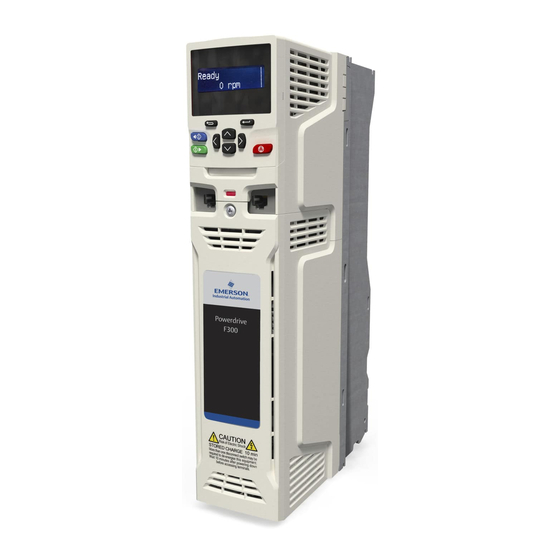
Emerson Powerdrive F300 User Manual (289 pages)
Universal Variable Speed AC drive for induction and permanent magnet motors
Brand:
Emerson
| Category:
Controller
| Size: 34.17 MB
Table of Contents
How to Use this Guide
3
Table of Contents
4
1 Safety Information
8
Warnings, Cautions and Notes
8
Electrical Safety - General Warning
8
System Design and Safety of Personnel
8
Environmental Limits
8
Access
8
Fire Protection
8
Compliance with Regulations
8
Motor
8
Adjusting Parameters
8
Electrical Installation
9
2 Product Information
10
AC Drive for Fans, Pumps and Compressors
10
Model Number
10
Ratings
11
Normal Duty
11
Operation of Motor Protection
11
200 V Drive Ratings
11
400 V Drive Ratings
12
575 V Drive Ratings
13
690 V Drive Ratings
13
Operating Modes
14
Typical Short Term Overload Limits
14
Open Loop Mode
14
RFC-A/S Mode
14
Drive Features
15
Nameplate Description
17
Typical Drive Rating Labels
17
Options Available with the Drive
18
Option Module Identification
19
Keypad Identification
19
Additional Options
19
Items Supplied with the Drive
20
Parts Supplied with the Drive
20
3 Mechanical Installation
22
Planning the Installation
22
Environmental/Fire Protection
22
Cooling
22
Safety Information
22
Electromagnetic Compatibility
23
Hazardous Areas
23
Terminal Cover Removal
23
Removing the Terminal Covers
24
Location and Identification of Terminal Covers
24
Removing the Size 3 Terminal Covers
26
Removing the Size 4 Terminal Covers
26
Removing the Size 5 Terminal Covers
27
Removing the Size 6 Terminal Covers
27
Removing the Finger-Guard and DC Terminal Cover Break-Outs
28
Removing the Size 7 to 11 Terminal Covers
28
Removing the Finger-Guard Break-Outs
28
Grommet Kits
28
Removing the Size 3 and 4 DC Terminal Cover Break-Outs
29
Installing / Removing Option Modules and Keypads
30
Installation of a Standard Option Module
30
Installing the First Option Module
30
Removal of a Standard Option Module
31
Installation and Removal of the KI-Keypad
31
Dimensions and Mounting Methods
32
Surface Mounting the Size 3 Drive
32
Surface Mounting the Size 4 Drive
33
Surface Mounting the Size 5 Drive
33
Surface Mounting the Size 6 Drive
34
Surface Mounting the Size 7 Drive
34
Surface Mounting the Size 8 Drive
35
Surface Mounting the Size 9A Drive
36
Surface Mounting the Size 9E and 10
37
Surface Mounting the Size 11E
38
Through-Panel Mounting the Size 3 Drive
39
Through Panel Mounting the Size 4 Drive
40
Through Panel Mounting the Size 5 Drive
40
Through Panel Mounting the Size 6 Drive
41
Through Panel Mounting the Size 7 Drive
41
Through Panel Mounting the Size 8 Drive
42
Through-Panel Mounting the Size 9A
42
Through-Panel Mounting the Size 9E and 10
43
Through-Panel Mounting the Size 11E
44
Mounting Brackets
45
Enclosure for Standard Drives
46
Recommended Spacing between the Drives
46
Spacing Required between the Drives
46
Enclosure Layout
47
Spacing Required between Drive / Enclosure and Drive / EMC Filter
47
Enclosure Sizing
49
Calculating the Size of a Sealed Enclosure
49
Calculating the Air-Flow in a Ventilated Enclosure
49
Enclosure Having Front, Sides and Top Panels Free to Dissipate Heat
49
Enclosure Design and Drive Ambient Temperature
50
Heatsink Fan Operation
50
Enclosing Standard Drive for High Environmental Protection
50
Example of IP65 Layout
50
Installing the Gasket
51
Through Panel Mounting
51
Installation of High IP Insert for Size 3
51
Installation of High IP Insert for Size 4
52
Installation of High IP Insert for Size 5
52
Environment Considerations
52
Example of IP54 Size 9 to 11 Through-Panel Layout
53
Option 2 for Achieving IP54 Size 9 to 11 Through-Panel Mounting
54
Description of Fixings
54
Option 3 for Achieving IP54 Size 9 to 11 through Panel Mounting
55
Environmental Considerations
55
Power Losses from the Front of the Drive When Through-Panel Mounted
55
External EMC Filter
56
Footprint Mounting the EMC Filter
57
Bookcase Mounting the EMC Filter
57
Size 7 to 10 Mounting of the EMC Filter
57
Size 3 External EMC Filter Dimensions
57
Size 4 External EMC Filter Dimensions
58
Size 5 External EMC Filter Dimensions
58
Size 7 External EMC Filter Dimensions
58
Size 8 External EMC Filter Dimensions
58
Size 9A External EMC Filter Dimensions
59
Size 9E and 10 External EMC Filter Dimensions
60
Size 11 External EMC Filter Dimensions
61
Line Reactor Mounting Dimensions for Size 9E, 10E and 11E
62
Input Line Reactor for Size 9 and 10
62
Input Line Reactor Force Cooled
62
Input Line Reactor for Size 11
62
Electrical Terminals
63
Location of the Power and Ground Terminals
63
Terminal Sizes and Torque Settings
65
Drive Power Terminal Data
65
Drive Control and Relay Terminal Data
65
Plug-In Terminal Block Maximum Cable Sizes
65
Routine Maintenance
66
Real Time Clock Battery Replacement
66
KI-HOA Keypad RTC (Rear View)
66
Fan Removal Procedure
67
Removal of the Size 3, 4 and 5 Heatsink Fan
67
Removal of the Size 6 Heatsink Fan
67
4 Electrical Installation
68
Power Connections
69
AC and DC Connections
69
Size 3 Power Connections
69
Size 4 Power Connections
70
Size 5 Power Connections
71
Size 6 Power Connections
72
Size 7 and 8 Power Connections
73
Size 9A Power Connections
73
Size 9E and 10E Power Connections
74
Size 11E Power Connections
74
Ground Connections
75
Size 3 and 4 Ground Connections
75
Size 5 Ground Connections
75
Size 6 Ground Connections
75
AC Supply Requirements
76
Size 7 to 10 Ground Connections
76
Size 11E Ground Connections
76
Protective Ground Cable Ratings
76
Supply Types
77
Supplies Requiring Line Reactors
77
Input Line Reactor Specification for Size 9E, 10E and 11E
78
Input Inductor Calculation
78
Size 9E, 10E and 11E Model and Line Reactor Part Number
78
Input Line Reactor Ratings
78
Supplying the Drive with DC
79
DC Bus Paralleling
79
24 VDC Supply
80
DC Bus Paralleling Kit Part Numbers
80
24 VDC Supply Connections
80
Location of the 24 VDC Power Supply Connection on Size 6
80
Heatsink Fan Supply
81
Location of the 24 VDC Power Supply Connection on Size 8 to 11
81
Ratings
81
AC Input Current and Fuse Ratings (200 V)
82
AC Input Current and Fuse Ratings (400 V)
82
AC Input Current and Fuse Ratings (575 V)
83
AC Input Current and Fuse Ratings (690 V)
83
Cable Ratings (200 V)
84
Cable Ratings (400 V)
84
Cable Ratings (575 V)
85
Cable Ratings (690 V)
85
Output Circuit and Motor Protection
86
Main AC Supply Contactor
86
Cable Types and Lengths
86
Fuse Types
86
High-Capacitance/Reduced Diameter Cables
87
Motor Winding Voltage
87
Multiple Motors
87
Maximum Motor Cable Lengths
87
Ground Leakage
88
EMC (Electromagnetic Compatibility)
88
Output Contactor
88
Use of Residual Current Device (RCD)
88
Grounding Hardware
89
Drive and EMC Filter Cross Reference
89
Installation of Grounding Clamp
89
Internal EMC Filter
90
Installation of Grounding Clamp (Size 5)
90
Installation of Grounding Clamp (Size 6)
90
Installation of Grounding Bracket (All Sizes -Size 3 Shown)
90
Removal of the Size 3/4/5/6 Internal EMC Filters
91
Removal of Size 7,8,9A Internal EMC Filter and Line to Ground Varistor
91
Line to Ground Varistors
92
Removal of Size 9E and 10E Line to Ground Varistors
92
Removal of Line to Ground Varistors
92
General Requirements for EMC
93
Ground (Earth) Connections
93
General EMC Enclosure Layout Showing Ground Connections
93
Compliance with en 61800-3:2004
94
Compliance with Generic Emission Standards
94
Cable Layout
94
Drive Cable Clearances
94
Supply and Ground Cable Clearance
95
Sensitive Signal Circuit Clearance
95
Grounding the Drive, Motor Cable Shield and Filter
95
Variations in the EMC Wiring
96
Interruptions to the Motor Cable
96
Terminal Block in the Enclosure
96
Using a Motor Isolator / Disconnect-Switch
96
Communications Connections
97
Isolation of the 485 Serial Communications Port
97
Surge Suppression for Digital and Unipolar Inputs and Outputs
97
Surge Suppression for Analog and Bipolar Inputs and Outputs
97
Control Connections
98
General
98
Default Terminal Functions
98
Control Terminal Specification
99
Safe Torque off (STO)
102
5 Getting Started
103
Understanding the Display
103
Keypad Operation
103
KI-HOA Keypad RTC
103
Power-Up Modes if Pr 01.052 = 3
104
Display Modes
104
Quick Access Mode
105
Keypad Shortcuts
105
Mode Examples
105
Menu Structure
106
Menu 0
106
Parameter Navigation
106
Menu 0 Copying
106
Advanced Menus
107
Display Messages
107
Advanced Menu Descriptions
107
KI-Keypad Set-Up Parameters
107
Changing the Operating Mode
108
Saving Parameters
108
Alarm Indications
108
Option Module and NV Media Card/Other Status Indications at Power-Up
108
Restoring Parameter Defaults
109
Parameter Access Level and Security
109
User Security Level / Access Level
109
User Security Code
109
Displaying Parameters with Non-Default Values Only
110
Displaying Destination Parameters Only Communications
110
485 Serial Communications
110
USB/EIA232 to EIA485 Communications
110
6 Basic Parameters
111
Menu 0: Basic Parameters
111
Menu 0 Logic Diagram
114
Parameter Descriptions
116
Pr MM.000
116
Commonly Used Functions in XX.000
116
Functions in Pr MM.000
117
Full Descriptions
118
Parameter X.00
118
Speed Limits
118
Ramps, Speed Reference Selection, Current Limit
118
Voltage Boost, (Open-Loop), Speed-Loop PID Gains
119
Monitoring
120
Ramp Mode Selector, Stop and Torque Mode Selectors
120
Fixed and Variable V/F Characteristics
120
Standard Ramp
120
Standard Ramp with Motor Voltage Boost
121
Motor Parameters
125
Operating-Mode Selection
126
Status Information
126
Additional Parameters for RFC-S Sensorless Control
127
Fire Mode
129
Advanced Process PID
130
7 Running the Motor
134
Quick Start Connections
134
Basic Requirements
134
Minimum Control Connection Requirements for each Control Mode
134
Changing the Operating Mode
134
Minimum Connections to Get the Motor Running in any Operating Mode
135
Quick Start Commissioning / Start-Up
139
Open Loop
139
RFC - a Sensorless
140
Induction Motor Without Position Feedback
140
RFC-S Sensorless
141
Permanent Magnet Motor Without Position Feedback
141
RFC-S Mode Dyneo LSRPM Motor Set-Up with V01.12.02.00 Onwards Firmware
142
Dyneo LSRPM 1500/1800 Rpm Motors
143
Dyneo LSRPM 2400/3000 Rpm Motors
144
Dyneo LSRPM 3600/4500/5500 Rpm Motors
145
Power-Up the Drive
146
Quick Start Commissioning / Start-Up Using Powerdrive F300 Connect (V02.00.00.00 Onwards)
146
Use of Motor Database for LSRPM Motor for Use in RFC-S Sensorless Mode
148
8 Optimization
151
Motor Map Parameters
151
Open Loop Motor Control
151
RFC-A Sensorless Mode
154
RFC-S Sensorless Mode
157
Motor Thermal Protection
159
Switching Frequency
160
High Speed Operation
160
Field Weakening (Constant Power) Operation
160
Sample Rates for Various Control Tasks at each Switching Frequency
160
Permanent Magnet Motor High Speed Operation
161
Maximum Speed / Frequency
161
Quasi-Square Wave
161
Torque and Rated Voltage against Speed
161
9 NV Media Card Operation
162
Introduction
162
NV Media Card Support
162
Installation of the NV Media Card
162
Transferring Data
163
Writing to the NV Media Card
163
Reading from the NV Media Card
163
SMARTCARD and SD Card Codes
163
Data Block Header Information
164
Auto Saving Parameter Changes
164
Booting up from the NV Media Card on Every Power up
164
Setting and Clearing the NV Media Card Warning Suppression Flag
164
NV Media Card Parameters
165
Key to Parameter Table Coding
165
NV Media Card Trips
166
10 Onboard PLC
167
Onboard PLC and Machine Control Studio
167
Benefits
167
Features
167
Tasks
167
Onboard PLC Parameters
168
11 Advanced Parameters
169
Menu Descriptions
169
Powerdrive F300 User Guide Issue Number
169
Feature Look-Up Table
170
Parameter Ranges and Variable Minimum/Maximums
172
Voltage Ratings Dependant Values
178
Menu 1: Frequency / Speed Reference
180
Menu 1 Logic Diagram
180
Menu 2: Ramps
184
Menu 2 Logic Diagram
184
Menu 3: Frequency Slaving, Speed Feedback and Speed Control
187
Menu 3 Open-Loop Logic Diagram
187
Menu 3 RFC-A, RFC-S Logic Diagram
188
Menu 4: Torque and Current Control
191
Menu 4 Open Loop Logic Diagram
191
Menu 4 RFC-A Logic Diagram
192
Menu 4 RFC-S Logic Diagram
193
Menu 5: Motor Control
195
Menu 5 Open-Loop Logic Diagram
195
Menu 5 RFC-A, RFC-S Logic Diagram
196
Menu 6: Sequencer and Clock
200
Menu 6 Logic Diagram
200
Menu 7: Analog I/O
203
Menu 7 Logic Diagram
203
Menu 8: Digital I/O
206
Menu 8 Logic Diagram
206
Menu 9: Programmable Logic, Motorized Pot, Binary Sum and Timers
210
Menu 9 Logic Diagram: Programmable Logic
210
Menu 9 Logic Diagram: Motorized Pot and Binary Sum
211
Menu 9 Logic Diagram: Timers
212
Menu 9 Logic Diagram: Scope Function
213
Menu 10: Status and Trips
216
Defaults for Pr 10.030, Pr 10.031 and Pr 10.061
217
Menu 11: General Drive Set-Up
218
Menu 12: Threshold Detectors and Variable Selectors
220
Menu 12 Logic Diagram
220
Menu 12: Threshold Detectors and Variable Selectors
222
Menu 14: User PID Controller
224
Menu 14 Logic Diagram
224
Menus 15, 16 and 17: Option Module Set-Up
228
Parameters Common to All Categories
228
Location of Option Module Slots and Their Corresponding Menu Numbers
228
Menu 18: Application Menu 1
229
Menu 19: Application Menu 2
229
Menu 20: Application Menu 3
229
Menu 22: Additional Menu 0 Set-Up
230
Menu 29: Dyneo LSRPM Motor Configuration
231
Drive Technical Data
232
Power and Current Ratings
232
Maximum Permissible Continuous Output Current 40 °C Ambient
232
Permissible Continuous Output 40°C Ambient with IP Insert Installed
234
Maximum Permissible Continuous Output Current 50°C
235
Power Dissipation
237
Losses 40° C Ambient
237
Losses 40°C Ambient with High IP Insert Installed
239
Losses 50° C Ambient
240
Supply Requirements
242
Line Reactors
242
Storage
242
IP / UL Rating
242
Corrosive Gasses
243
Vibration
243
Starts Per Hour
243
Accuracy and Resolution
243
Acoustic Noise
244
Overall Dimensions
244
Weights
244
Safe Torque off Data
244
Cable Ratings (200/400V)
248
Cable Ratings (575/690 V)
249
Size 9E And10 Model and Line Reactor Part Number
250
Input Line Reactor Dimensions
250
Maximum Motor Cable Lengths (200/400 V Drives)
251
Maximum Motor Cable Lengths (575/690 V Drives)
252
Torque Settings
253
External EMC Filter Terminal Data
254
Electromagnetic Compatibility (EMC)
255
Emission
255
Immunity Compliance
255
Size 3 Emission Compliance (200/400 V Drives)
255
Size 5 Emission Compliance (400/575 V Drives)
256
Size 6 Emission Compliance (200/400/575 V Drives)
256
Size 7 Emission Compliance (200/400/575/690 V Drives)
256
Size 8 Emission Compliance (200 V Drives)
256
Size 8 Emission Compliance (400/575/690 V Drives)
257
Size 9E and 10E Emission Compliance (200/400/575/690 V Drives)
257
Optional External EMC Filters
258
EMC Filter Ratings
258
EMC Filter Cross Reference
258
Optional External EMC Filter Details
258
Overall EMC Filter Dimensions
259
EMC Filter Torque Settings
259
Optional External EMC Filter Dimensions
259
Optional External EMC Filter Terminal Data
259
Trip Indications
260
Location of the Status LED
260
Status Modes (Keypad and LED Status)
260
Identifying a Trip / Trip Source
261
Trips Associated with Xxyzz Sub-Trip Number
261
Sub-Trip Identification
261
Key to Sub-Trip Number
261
Trips, Sub-Trip Numbers
262
Serial Communications Look up Table
280
Trip Categories
281
Internal / Hardware Trips
282
Status Indications
282
Programming Error Indications
282
Option Module/Nv Media Card and Other Status Indications at Power-Up
282
Displaying the Trip History
283
Behaviour of the Drive When Tripped
283
14 UL Listing Information
284
Overload, Overcurrent and Overspeed Protection
284
Short-Circuit Protection for Branch Circuits
284
Control Circuit Protection
284
General
284
Wiring Terminal Markings
284
Mounting
285
Listed Accessories
285
Cul Marking Requirements
285
Option Modules
285
Environment
285
Index
286
Advertisement
Emerson Powerdrive F300 Reference Manual (342 pages)
Brand:
Emerson
| Category:
DC Drives
| Size: 3.82 MB
Emerson Powerdrive F300 Getting Started Manual (111 pages)
Frame Sizes 3 to 11
Brand:
Emerson
| Category:
Controller
| Size: 14.47 MB
Table of Contents
Safety Information
5
Product Information
7
Nameplate Description
8
Ratings
9
Drive Features
14
Options / Accessories
16
Mechanical Installation
18
Drive Dimensions
19
Surface Mounting
21
Terminal Size and Torque Settings
25
Enclosure
26
EMC Filters
28
Electrical Installation
33
Supply Types
34
Power Connections
35
Ground Connections
43
Shield Connections
44
Communications Connections
45
Getting Started
46
Keypad Operation
47
Menu
50
Advanced Menus
51
Changing the Operating Mode
52
Restoring Parameter Defaults
53
Parameter Descriptions
57
Running the Motor
62
Quick Start / Start-Up
67
Diagnostics
83
Optimization
85
Motor Thermal Protection
96
Switching Frequency
98
High Speed Operation
99
NV Media Card Operation
101
NV Media Card Support
102
Transferring Data
103
Further Information
104
UL Listing Information
105
Short-Circuit Protection for Branch Circuits
106
Wiring Terminal Markings
107
Listed Accessories
108
Advertisement
Advertisement
Related Products
Emerson FXMP25
Emerson Fisher Type 667 size 100
Emerson Fisher PRX Series
Emerson FieldQ Q40
Emerson FieldQ Q65
Emerson FieldQ Q950
Emerson FieldQ Q150
Emerson EL-O-Matic FS 0350 Series
Emerson EL-O-Matic FS 0200 Series
Emerson EL-O-Matic FD 0065 Series
Emerson Categories
Controller
Control Unit
Transmitter
Measuring Instruments
Fan
More Emerson Manuals
Login
Sign In
OR
Sign in with Facebook
Sign in with Google
Upload manual
Upload from disk
Upload from URL