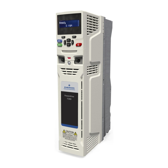
Emerson Powerdrive F300 User Manual
Universal variable speed ac drive for
induction and permanent magnet
motors
Hide thumbs
Also See for Powerdrive F300:
- Reference manual (342 pages) ,
- Getting started manual (111 pages)

Related Manuals for Emerson Powerdrive F300


Summary of Contents for Emerson Powerdrive F300
- Page 1 User Guide Powerdrive F300 Model size 3 to 11 Universal Variable Speed AC drive for induction and permanent magnet motors Part Number: 0479-0003-02 Issue: 2...
-
Page 2: Issue Number
This may also apply to drives returned from an Emerson Industrial Automation Service Centre or Repair Centre. If there is any doubt please contact the supplier of the product. - Page 3 How to use this guide This user guide provides complete information for installing and operating the drive from start to finish. The information is in logical order, taking the reader from receiving the drive through to fine tuning the performance. NOTE There are specific safety warnings throughout this guide, located in the relevant sections.
-
Page 4: Table Of Contents
Heatsink fan supply ..........81 Ratings ..............81 Output circuit and motor protection .....86 Ground leakage ...........88 4.10 EMC (Electromagnetic compatibility) ....88 4.11 Communications connections ......97 4.12 Control connections ..........98 4.13 Safe Torque Off (STO) ........102 Powerdrive F300 User Guide Issue Number: 2... -
Page 5: Table Of Contents
............284 14.3 Short-circuit protection for branch circuits ..284 14.4 Control circuit protection ........284 14.5 Wiring terminal markings ........284 14.6 Environment ............285 14.7 Mounting ............285 14.8 Listed Accessories ..........285 14.9 cUL Marking requirements ........285 Powerdrive F300 User Guide Issue Number: 2... - Page 6 16915 Angoulême Cedex 9 SY16 3BE France This declaration applies to Powerdrive F300 variable speed drive The AC variable speed drive products listed above have been designed products, comprising models numbers as shown below: and manufactured in accordance with the following European...
- Page 7 CS10015 16915 Angoulême Cedex 9 SY16 3BE France This declaration applies to the Powerdrive F300 variable speed drive The harmonized standards used are shown below: product range, comprising model numbers composed as shown below: Adjustable speed electrical power drive Faaa-bbbbbbbbb Valid characters: EN 61800-5-1:2007 systems.
-
Page 8: Safety Information
Environmental limits Instructions in this User Guide regarding transport, storage, installation and use of the drive must be complied with, including the specified environmental limits. Drives must not be subjected to excessive physical force. Powerdrive F300 User Guide Issue Number: 2... -
Page 9: Electrical Installation
The drive contains capacitors that remain charged to a potentially lethal voltage after the AC supply has been disconnected. If the drive has been energized, the AC supply must be isolated at least ten minutes before work may continue. Powerdrive F300 User Guide Issue Number: 2... -
Page 10: Product Information
AC drive for fans, pumps and compressors Powerdrive F300 is an AC drive primarily aimed at energy-saving projects in fan pump and compressor applications. Features include sensor less motor control for both induction and permanent magnet motors for best-in-class energy efficiency. Fan and pump features for easy integration and user programming for application flexibility. -
Page 11: Ratings
Frame size 6 06200580 63.8 07200750 18.5 82.5 Frame size 7 07200940 103.4 07201170 128.7 08201490 163.9 Frame size 8 08201800 09202160 237.6 Frame size 9 09202660 292.6 10203250 357.5 Frame size 10 10203600 Powerdrive F300 User Guide Issue Number: 2... - Page 12 * These ratings are for 2 kHz switching frequency. For ratings at 3 kHz switching frequency refer to section 12.1.1 Power and current ratings (Derating for switching frequency and temperature) on page 232. Powerdrive F300 User Guide Issue Number: 2...
- Page 13 * These ratings are for 2 kHz switching frequency. For ratings at 3 kHz switching frequency refer to section 12.1.1 Power and current ratings (Derating for switching frequency and temperature) on page 232. Powerdrive F300 User Guide Issue Number: 2...
-
Page 14: Operating Modes
Flux control is not required because the motor is self excited by the permanent magnets which form part of the rotor. Full torque is available all the way down to zero speed, with salient motors. Powerdrive F300 User Guide Issue Number: 2... -
Page 15: Drive Features
17. Ground connections 3. Identification label 8. Relay connections 13. DC bus + 4. Status LED 9. Control connections 14. DC bus - 5. Option module slot 1 10. Communications port 15. Motor connections Powerdrive F300 User Guide Issue Number: 2... - Page 16 7. Option module slot 3 11. NV media card slot 15. Motor connections 4. Status LED 8. Relay connections 12. Ground connections * Common AC supply connections are internally linked on 6 pulse drives. Powerdrive F300 User Guide Issue Number: 2...
-
Page 17: Nameplate Description
The letters go in alphabetical order, starting with A in 1990 (B in 1991, C in 1992 etc). Example: A date code of W28 would correspond to week 28 of year 2013. Powerdrive F300 User Guide Issue Number: 2... -
Page 18: Options
2. Option module slot 1 5. CT Comms cable 3. Option module slot 2 6. NV media card Be aware of possible live terminals when inserting or removing the NV media card. WARNING Powerdrive F300 User Guide Issue Number: 2... - Page 19 Type Option Name Further Details SD Card Adaptor SD Card Adaptor Allows the drive to use an SD card for drive back-up Back-up SMARTCARD SMARTCARD www.controltechniques.com Used for parameter back-up with the drive Powerdrive F300 User Guide Issue Number: 2...
-
Page 20: Items Supplied With The Drive
24 V power supply connector Grounding bracket Surface mounting brackets Grounding clamp DC terminal cover grommets Terminal nuts M6 x 11 M8 x 12 M10 x 12 Supply and motor connector Finger guard grommets Powerdrive F300 User Guide Issue Number: 2... - Page 21 Table 2-10 Parts supplied with the drive (size 9A, 9E, 10E and 11E) Description Size 9A/9E Size 10E Size 11E Control connectors Relay connector 24 V power supply connector Grounding bracket Fan power supply connector Surface mounting brackets Powerdrive F300 User Guide Issue Number: 2...
-
Page 22: Mechanical Installation
) B o t t o m o f f i r e Bottom of fire enclosure e n c l o s u r e Powerdrive F300 User Guide Issue Number: 2... -
Page 23: Terminal Cover Removal
If the drive has failed in a manner that causes the display to go blank immediately, it is possible the capacitors will not be discharged. In this case, consult Control Techniques or their authorized distributor. Powerdrive F300 User Guide Issue Number: 2... - Page 24 AC / DC terminal cover AC / DC terminal cover 9A 9E 10E Motor terminal Control terminal Motor terminal Control terminal cover cover cover cover Control terminal Motor terminal cover cover Powerdrive F300 User Guide Issue Number: 2...
- Page 25 Optimization Diagnostics information information installation installation started parameters the motor Operation parameters data information Figure 3-4 Location and identification of terminal covers (size 11) AC terminal cover Control terminal cover Motor terminal cover Powerdrive F300 User Guide Issue Number: 2...
- Page 26 On size 4 drives, the Control / AC / Motor terminal cover must be removed before removal of the DC / Terminal cover. When replacing the terminal covers, the screws should be tightened to a maximum torque of 1 N m (0.7 lb ft). Powerdrive F300 User Guide Issue Number: 2...
- Page 27 On size 5 drives, the Control terminal cover must be removed before removal of the DC / Terminal cover right. When replacing the terminal covers, the screws should be tightened to a maximum torque of 1 N m (0.7 lb ft). Figure 3-8 Removing the size 6 terminal covers Powerdrive F300 User Guide Issue Number: 2...
- Page 28 Kit of 8 x double entry grommets 3470-0107-00 Size 11E- Kit of 8 x double entry grommets A: All sizes. B: Size 5 only. C: Size 6 only. D: Size 7 to 10. Powerdrive F300 User Guide Issue Number: 2...
- Page 29 (2). Remove any flash / sharp edges once the break- outs are removed. Use the DC terminal cover grommets supplied in the accessory box (Table 2-9 on page 20) to maintain the seal at the top of the drive. Powerdrive F300 User Guide Issue Number: 2...
-
Page 30: Installing / Removing Option Modules And Keypads
Installing the third option module • Repeat the above process. The drive has the facility for all three option module slots to be used at the same time, image (6) shows the three option modules installed. Powerdrive F300 User Guide Issue Number: 2... - Page 31 To remove, reverse the installation instructions. NOTE The keypad can be installed / removed while the drive is powered up and running a motor, providing that the drive is not operating in keypad mode. Powerdrive F300 User Guide Issue Number: 2...
-
Page 32: Dimensions And Mounting Methods
The inner holes (6.5 mm) x 2 are used for Unidrive SP size 1 retrofit applications. See Table 3-2 for further information. Powerdrive F300 User Guide Issue Number: 2... - Page 33 106 mm (4.17 in) 143 mm (5.63 in) (0.32 in) Æ 7.0 mm (0.28 in) NOTE The outer holes in the mounting bracket are to be used for surface mounting. See Table 3-2 for further information. Powerdrive F300 User Guide Issue Number: 2...
- Page 34 The outer holes in the mounting bracket are to be used for surface mounting. See Table 3-2 for further information. Figure 3-19 Surface mounting the size 7 drive 25 mm (0.98 in) 220 mm (8.66 in) 9.5 mm (0.39 in) 280 mm (11.02 in) 270 mm (10.63 in) Æ 9mm (0.35 in) Powerdrive F300 User Guide Issue Number: 2...
- Page 35 Figure 3-20 Surface mounting the size 8 drive 26 mm (1.02 in) 259 mm (10.20 in) 310 mm (12.21 in) 290 mm (11.42 in) 285 mm (11.22 in) 10 mm (0.39 in) Æ9 mm (0.35 in) (4 holes) Powerdrive F300 User Guide Issue Number: 2...
- Page 36 Figure 3-21 Surface mounting the size 9A drive 26 mm 259 mm (10.18 in) (1.01 in) 310 mm (12.20 in) 290 mm (11.42 in) (0.35 in) 285 mm (11.22 in) ∅ 9.0 mm (0.35 in) x 4 holes Powerdrive F300 User Guide Issue Number: 2...
- Page 37 Figure 3-22 Surface mounting the size 9E and 10 310 mm (12.21 in) 288 mm (11.34 in) 26 mm 259 mm (10.20 in) 285 mm (11.22 in) (1.02 in) 9 mm (0.35 in) Æ9.0 mm (0.35 in) x 4 holes Powerdrive F300 User Guide Issue Number: 2...
- Page 38 Figure 3-23 Surface mounting the size 11E 26 mm (1.02 in) 259 mm (10.19 in) Æ 9mm (0.35 in) 310 mm (12.21 in) 312 mm (12.28 in) x 4 holes 285 mm (11.22 in) 12 mm (0.47 in) Powerdrive F300 User Guide Issue Number: 2...
- Page 39 400 mm (14.37 in) (14.13 in) (15.75 in) 109 mm (4.29 in) Radius 1.0 mm (0.04 in) 38.5 mm 38.5 mm 67 mm (1.52 in) (1.52 in) (2.64 in) 77 mm (3.03 in) Powerdrive F300 User Guide Issue Number: 2...
- Page 40 (1.02 in) Æ5.0 mm (0.20 in) (x 4 holes) 68 mm (2.67 in) 68 mm (2.67 in) Radius 1.0 mm Æ6.5 mm (0.3 in) (0.04 in) (x 4 holes) 136 mm (5.35 in) Powerdrive F300 User Guide Issue Number: 2...
- Page 41 330 mm (12.99 in) 92 mm (3.62 in) 310 mm (12.20 in) 270 mm (10.63 in) 252 mm (9.92 in) 188 mm (7.40 in) 245 mm (9.65 in) 220 mm (8.66 in) ∅ 9mm (0.35 in) Powerdrive F300 User Guide Issue Number: 2...
- Page 42 100 mm Æ9.0 mm (0.35 in) 190 mm (7.48 in) 259 mm (10.18 in) 285 mm (11.22 in) (3.94 in) x 4 holes Æ5.0 mm (0.21 in) x 8 holes 32 mm (1.24 in) Powerdrive F300 User Guide Issue Number: 2...
- Page 43 259 mm (10.20 in) 310 mm (12.21 in) Æ9.0 mm (0.35 in) 285 mm (11.22 in) x 4 holes Æ5.5 mm (0.22 in) n5.5 typ. 8 places x 8 holes 31 mm (1.22 in) Powerdrive F300 User Guide Issue Number: 2...
- Page 44 190 mm (7.48 in) 122 mm 310 mm (12.21 in) 259 mm (10.19 in) x 4 holes (4.80 in) 285 mm (11.22 in) Æ 5.5 mm (0.21 in) x 12 holes 32 mm (1.26 in) Powerdrive F300 User Guide Issue Number: 2...
- Page 45 Hole size: 9 mm (0.35 in) Hole size: 9 mm (0.35 in) Hole size: 5.5 mm (0.22 in) 9E and 10E Hole size: 9 mm (0.35 in) Hole size: 9 mm (0.35 in) Powerdrive F300 User Guide Issue Number: 2...
-
Page 46: Enclosure For Standard Drives
* 50°C derating applies, refer to Table 12-3 Maximum permissible continuous output current @ 50 °C (122 °F) on page 235. NOTE When through-panel mounted, ideally drives should be spaced 45 mm (1.77 in) to maximize panel stiffness. Powerdrive F300 User Guide Issue Number: 2... - Page 47 2. Power cabling must be at least 100 mm (4 in) from the drive in all directions Table 3-5 Spacing required between drive / enclosure and drive / EMC filter (size 3 to 8) Drive Size Spacing (B) 0 mm (0.00 in) 30 mm (1.18 in) Powerdrive F300 User Guide Issue Number: 2...
- Page 48 Optional braking resistor and overload Table 3-6 Spacing required between drive / enclosure and drive / EMC filter (size 9 to 11) Drive Size Spacing (B) 9A/9E 45 mm (1.77 in) 10E/11E Powerdrive F300 User Guide Issue Number: 2...
- Page 49 Ratio of Where: is the air pressure at sea level is the air pressure at the installation Typically use a factor of 1.2 to 1.3, to allow also for pressure-drops in dirty air-filters. Powerdrive F300 User Guide Issue Number: 2...
-
Page 50: Enclosure Design And Drive Ambient Temperature
Refer to section 3.13.2 Fan removal procedure on page 67 for information on fan removal. Size 6 to 11 are also installed with a variable speed fan to ventilate the capacitor bank. Powerdrive F300 User Guide Issue Number: 2... - Page 51 3. Close the hinged baffle as shown (1). To remove the high IP insert, reverse the above instructions. The guidelines in Table 3-7 should be followed. Through panel securing bracket Through panel securing bracket Powerdrive F300 User Guide Issue Number: 2...
- Page 52 A current derating must be applied to the drive if the high IP insert is installed. Derating information is provided in section 12.1.1 Power and current ratings (Derating for switching frequency and temperature) on page 232. Failure to do so may result in nuisance tripping. Powerdrive F300 User Guide Issue Number: 2...
- Page 53 3. If an internal backplate is not available a separate clamp can be used to simulate option 2. See Figure 3-45 on page 55. 4 off sealing clamps are supplied in the through panel mounting kit. Powerdrive F300 User Guide Issue Number: 2...
- Page 54 (9.96 in) placed centrally 817 mm along (32.17 in) length 5 mm (0.2 in) 817 mm (32.17 in) Table 3-8 Description of fixings Item Description Bolt Flat washer Nylon washer Flat washer Spring washer Powerdrive F300 User Guide Issue Number: 2...
- Page 55 Table 3-10 Power losses from the front of the drive when through-panel mounted Frame size Power loss ≤ 50 W ≤ 75 W ≤ 100 W ≤ 100 W ≤ 204 W ≤ 347 W ≤ 480 W 9A/9E/10E/11E Powerdrive F300 User Guide Issue Number: 2...
-
Page 56: External Emc Filter
11502480 to 11503150 4200-0690 690 V 07600230 to 07600730 4200-0672 08600860 to 08601080 4200-1662 9.35 9.35 09601250 to 09601550 (9A) 4200-1660 09601250 to 09601550 (9E) 4200-2210 10601720 to 10601970 4200-2210 11602250 to 11603050 4200-0690 Powerdrive F300 User Guide Issue Number: 2... - Page 57 56 mm 41 mm 426 mm 83 mm 5.5 mm 5.5 mm 2.5 mm (15.12 in) (16.30 in) (2.21 in) (1.61 in) (16.77 in) (3.27 in) (0.22 in) (0.22 in) 4200-3480 (14 AWG) Powerdrive F300 User Guide Issue Number: 2...
- Page 58 240 mm 255 mm 55 mm 150 mm 205 mm 270 mm 90 mm 6.5 mm (9.45 in) (10.04 in) (2.17 in) (5.90 in) (8.07 in) (10.63 in) (3.54 in) (10.26 in) 4200-1662 Powerdrive F300 User Guide Issue Number: 2...
- Page 59 210 mm 2 mm 40 mm 339 mm 73 mm 60 mm 230 mm (8.66 in) (6.70 in) (4.72 in) (8.27 in) (0.08 in) (1.57 in) (13.34) (2.87 in) (2.36 in) (9.06 in) 4200-1660 Powerdrive F300 User Guide Issue Number: 2...
- Page 60 180 mm 57 mm 105 mm 225 mm 40 mm 360 mm 245 mm 11 mm 4200-2210 (11.02) (7.09) (2.24 mm) (4.13 in) (8.86 in) (1.57 in) (14.7 in) (9.65 in) (0.43 in) Powerdrive F300 User Guide Issue Number: 2...
- Page 61 (12.05 in) (1.46 in) (0.32 in) (5.32 in) (0.47 in) (4.72 in) (15.20 in) (2.36 in) (9.25 in) (0.08 in) (0.79 in) (8.27 in) (10.2 in) (0.41 in) (0.98 in) (0.59 in) 4200-0690 Powerdrive F300 User Guide Issue Number: 2...
-
Page 62: Line Reactor Mounting Dimensions For Size 9E, 10E And 11E
Æ 9 mm x 5 mm between centres (0.35 in x 0.20 in) For overall dimensions and other details, refer to section 4.2.3 Input line reactor specification for size 9E, 10E and 11E on page 78. Powerdrive F300 User Guide Issue Number: 2... -
Page 63: Electrical Terminals
Figure 3-57 Locations of the power and ground terminals (size 3 to 8) 1. Control terminals 4. Ground connections 7. DC bus - 2. Relay terminals 5. AC power terminals 8. DC bus + 3. Additional ground connection 6. Motor terminals Powerdrive F300 User Guide Issue Number: 2... - Page 64 Figure 3-58 Location of the power and ground terminals (size 9A/9E, 10E and 11E) 9A/9E/10E 1. Control terminals 3. Ground connections 5. Motor terminals 2. Relay terminals 4. AC power terminals 6. DC bus + Powerdrive F300 User Guide Issue Number: 2...
- Page 65 (1.70 Ib ft) (3.7 lb ft) (6 AWG) 4200-3690 4200-3021 25 N m 4200-4460 (18.4 lb ft) 4200-1660 25 N m 4200-2210 (18.4 lb ft) 4200-0400 25 N m (18.4 lb ft) 4200-0690 Powerdrive F300 User Guide Issue Number: 2...
-
Page 66: Routine Maintenance
1. To remove the battery cover insert a flat head screwdriver into the slot as shown (1), push and turn anti-clockwise until the battery cover is released. 2. Replace the battery (the battery type is: CR2032). 3. Reverse point 1 above to replace battery cover. NOTE Ensure the battery is disposed of correctly. Powerdrive F300 User Guide Issue Number: 2... - Page 67 C: Depress and hold the locking release on the fan cable lead as shown (2). D: With the locking release depressed (2), take hold of the fan supply cable and carefully pull to separate the connectors. Powerdrive F300 User Guide Issue Number: 2...
- Page 68 If the motor load is capable of rotating the motor when the supply is disconnected, then the motor must be isolated from the drive before WARNING gaining access to any live parts. Powerdrive F300 User Guide Issue Number: 2...
-
Page 69: Power Connections
Figure 4-1 Size 3 power connections Ground connection studs Additional ground connection AC Connections Optional EMC filter Optional line reactor Fuses Motor Supply Mains Optional ground Supply Ground connection See Figure 4-9 for information on ground connections. Powerdrive F300 User Guide Issue Number: 2... - Page 70 If the heatsink mounted resistor is used, an overload protection device is not required. The resistor is designed to fail safely under fault conditions. See Figure 4-9 for information on ground connections. Powerdrive F300 User Guide Issue Number: 2...
- Page 71 If the heatsink mounted resistor is used, an overload protection device is not required. The resistor is designed to fail safely under fault conditions. See Figure 4-10 for further information on ground connections. Powerdrive F300 User Guide Issue Number: 2...
- Page 72 Figure 4-4 Size 6 power connections Supply Connections Motor Connections Ground connection studs Optional EMC filter Optional line reactor Fuses Motor Mains Supply Optional ground Supply Ground connection See Figure 4-11 for further information on ground connections. Powerdrive F300 User Guide Issue Number: 2...
- Page 73 Optional EMC filter Motor connections Motor connections Motor Optional ground connection See Figure 4-12 for further information on ground connections. Motor Optional ground connection See Figure 4-12 for further information on ground connections. Powerdrive F300 User Guide Issue Number: 2...
- Page 74 Table 4-3 and Table 4-2 on page 78 must be used with size Optional ground 9E and10E. Failure to provide sufficient reactance could connection damage or reduce the service life of the drive. CAUTION * Connect to either terminal. Powerdrive F300 User Guide Issue Number: 2...
- Page 75 On size 5, the supply and motor ground connections are made using the M5 studs located near the plug-in power connector. Refer to Figure 4-10 for additional ground connection. Figure 4-10 Size 5 ground connections 1. Ground connection studs 1. Ground connection studs. Powerdrive F300 User Guide Issue Number: 2...
-
Page 76: Ac Supply Requirements
Maximum supply imbalance: 2 % negative phase sequence (equivalent to 3 % voltage imbalance between phases). Frequency range: 45 to 66 Hz For UL compliance only, the maximum supply symmetrical fault current must be limited to 100 kA Powerdrive F300 User Guide Issue Number: 2... - Page 77 The current rating of the line reactors should be as follows: Continuous current rating: Not less than the continuous input current rating of the drive Repetitive peak current rating: Not less than twice the continuous input current rating of the drive Powerdrive F300 User Guide Issue Number: 2...
- Page 78 To calculate the inductance required (at Y%), use the following equation: --------- - ------ - ----------- - × × 2πfI Where: I = drive rated input current (A) L = inductance (H) f = supply frequency (Hz) V = voltage between lines Powerdrive F300 User Guide Issue Number: 2...
-
Page 79: Supplying The Drive With Dc
Figure 4-16 DC bus paralleling (size 3 shown) There are limitations to the combinations of drives which can be used in this configuration. For application data, contact the supplier of the drive. Powerdrive F300 User Guide Issue Number: 2... -
Page 80: Vdc Supply
Maximum power supply requirement at 24 V 40 W Recommended fuse 3 A, 50 Vdc Minimum and maximum voltage values include ripple and noise. Ripple and noise values must not exceed 5 %. Powerdrive F300 User Guide Issue Number: 2... -
Page 81: Heatsink Fan Supply
The AC supply to the drive must be installed with suitable protection against overload and short-circuits. Table 4-7 shows recommended fuse ratings. Failure to observe this requirement will cause risk of fire. WARNING Powerdrive F300 User Guide Issue Number: 2... - Page 82 CC, J or T** 06400380 06400480 CC, J or T** 06400630 07400790 07400940 CC, J or T** 07401120 08401550 08401840 09402210 09402660 10403200 10403610 11404370 11404870 11405070 ** These fuses are fast acting. Powerdrive F300 User Guide Issue Number: 2...
- Page 83 Refer to local wiring regulations for the correct size of cables. CAUTION Powerdrive F300 User Guide Issue Number: 2...
- Page 84 2 x 150 2 x 150 2 x 350 2 x 300 11404370 2 x 185 4 x 3/0 11404870 4 x 95 2 x 400 2 x 240 4 x 4/0 11405070 Powerdrive F300 User Guide Issue Number: 2...
- Page 85 B1 - Separate cables in conduit. A fuse or other protection must be included in all live connections to the B2 - Multicore cable in conduit. AC supply. C - Multicore cable in free air. Powerdrive F300 User Guide Issue Number: 2...
-
Page 86: Output Circuit And Motor Protection
125 m 90 m 250 m (820 ft) (607 ft) (410 ft) (295 ft) 08401840 09402210 250 m (820 ft) 09402660 10403200 250 m (820 ft) 10403610 11404370 11404870 250 m (820 ft) 11405070 Powerdrive F300 User Guide Issue Number: 2... - Page 87 For details of inductor sizes refer to the supplier of the drive. capacitance; if a cable of this type is used, the maximum cable length is half that quoted in the tables, (Figure 4-20 shows how to identify the two types). Powerdrive F300 User Guide Issue Number: 2...
-
Page 88: Ground Leakage
- long cables and connections outside a building on WARNING interrupted with the motor running at high current and low page 96 for increased surge immunity of control circuits where control speed. wiring is extended. Powerdrive F300 User Guide Issue Number: 2... - Page 89 This includes the internal WARNING EMC filter. NOTE The installer of the drive is responsible for ensuring compliance with the EMC regulations that apply in the country in which the drive is to be used. Powerdrive F300 User Guide Issue Number: 2...
- Page 90 28 mA for size 3 is unacceptable. See section 4.10.2 for details of removing and installing the internal EMC filter. Powerdrive F300 User Guide Issue Number: 2...
- Page 91 The Internal EMC filter on size 9E, 10E and 11E cannot be removed. Remove the three M4 terminal nuts (1). Lift away the cover (2) to expose the M4 Torx internal EMC filter removal screw. Finally remove the M4 Powerdrive F300 User Guide Issue Number: 2...
- Page 92 To electrically disconnect the line to ground varistors, remove the two screws highlighted (1) above and remove the bracket (2). NOTE The line to ground varistors should only be removed in special circumstances. Powerdrive F300 User Guide Issue Number: 2...
- Page 93 It must not be connected directly to the power earth busbar. Optional ground connection Powerdrive F300 User Guide Issue Number: 2...
- Page 94 Operation in the second environment In all cases a shielded motor cable must be used, and an EMC filter is required for all drives with a rated input current of less than 100 A. Powerdrive F300 User Guide Issue Number: 2...
- Page 95 Figure 4-38 Sensitive signal circuit clearance ≥300 mm (12 in) Sensitive signal cable Avoid placing sensitive signal circuits in a zone 300 mm (12 in) in the area immediately surrounding the power module. Ensure good EMC grounding. Powerdrive F300 User Guide Issue Number: 2...
- Page 96 The input/output ports for the control circuits are designed for general use within machines and small systems without any special precautions. These circuits meet the requirements of EN 61000-6-2:2005 (1 kV surge) provided the 0 V connection is not grounded. Powerdrive F300 User Guide Issue Number: 2...
-
Page 97: Communications Connections
Table 4-21 Isolated serial comms lead details Part number Description 4500-0096 CT USB Comms cable The “isolated serial communications” lead has reinforced insulation as defined in IEC60950 for altitudes up to 3,000 m. Powerdrive F300 User Guide Issue Number: 2... -
Page 98: Control Connections
The shield of these signal cables must be connected to ground close to the point of exit of the motor cable, to avoid this noise current spreading through the control system. Powerdrive F300 User Guide Issue Number: 2... - Page 99 Reset resistance User defined in Pr 07.056 [07.061] Short-circuit detection resistance 50 Ω ± 40 % Common to all modes 12 bits (11 bits plus sign) Resolution 4 ms Sample / update period Powerdrive F300 User Guide Issue Number: 2...
- Page 100 -3 V to +30 V voltage range >2 mA @15 V from IEC 61131-2, type 1, Impedance 6.6 k Ω Input thresholds 10 V ±0.8 V from IEC 61131-2, type 1 Sample / Update period 2 ms Powerdrive F300 User Guide Issue Number: 2...
- Page 101 To prevent the risk of a fire hazard in the event of a fault, a fuse or other over-current protection must be installed in the Default contact condition Closed when power applied and drive OK relay circuit. WARNING Update period 4 ms Powerdrive F300 User Guide Issue Number: 2...
-
Page 102: Safe Torque Off (Sto)
1 ms, so that it is compatible with safety controllers whose outputs are subject to a dynamic test with a pulse width not exceeding 1 ms. Note on the use of servo motors, other permanent-magnet motors, reluctance motors and salient-pole induction motors. Powerdrive F300 User Guide Issue Number: 2... -
Page 103: Getting Started
Table 5-3. Character ABCD 32 bit number with decimal point 21474836.47 Table 5-3 Hand/Off/Auto mode 16 bit binary number 0100001011100101 Pr 01.052 Power up Hand/Off/Auto disabled Auto Mode Off Mode See table Table 5-4 Powerdrive F300 User Guide Issue Number: 2... - Page 104 The navigation keys can only be used to move between menus if Pr 00.049 has been set to show 'All Menus'. Refer to section 5.9 Parameter access level and security on page 109. Powerdrive F300 User Guide Issue Number: 2...
- Page 105 NOTE For new parameter-values to apply after the line power supply to the drive is interrupted, new values must be saved. Refer to section 5.7 Saving parameters on page 108. Powerdrive F300 User Guide Issue Number: 2...
-
Page 106: Menu Structure
* The option module menus (S.mm.ppp) are only displayed if option modules are installed. Where S signifies the option module slot number and the mm.ppp signifies the menu and the parameter number of the option module's internal menus and parameter. Powerdrive F300 User Guide Issue Number: 2... -
Page 107: Advanced Menus
The motor pre-heat function is active Enabled set-up menu. The drive is performing a ‘phasing test on Phasing Enabled enable’ To exit from the keypad set-up menu press the escape button. Below are the keypad set-up parameters. Powerdrive F300 User Guide Issue Number: 2... -
Page 108: Changing The Operating Mode
* If the drive is in the under voltage state (i.e. when the control terminal 1 & 2 are being supplied from a low voltage DC supply) a value of 1001 must be entered into Pr mm.000 to perform a save function. Powerdrive F300 User Guide Issue Number: 2... -
Page 109: Restoring Parameter Defaults
0 and press the button. The User Security has now been disabled, and will not have to be unlocked each time the drive is powered up to allow read / write access to the parameters. Powerdrive F300 User Guide Issue Number: 2... -
Page 110: Displaying Parameters With Non-Default Values Only
1200 (2), via a option module or via the The Powerdrive F300 drive offers a 2 wire 485 interface. This enables 2400 (3), comms interface itself. If it is the drive set-up, operation and monitoring to be carried out with a PC or... -
Page 111: Basic Parameters
±VM_SPEED_FREQ_REF Hz / rpm 0.0 Hz / rpm RW Num ±VM_SPEED_ Preset Reference 3 {01.023} 0.0 Hz RW Num FREQ_REF Hz 00.026 Overspeed Threshold {03.008} 0 to 40000 rpm 0 rpm RW Num Powerdrive F300 User Guide Issue Number: 2... - Page 112 , Non- 00.054 {05.064} salient Speed Mode salient Low Speed 0.0 to 00.055 Sensorless {05.071} 20.0 % RW Num 1000.0 % Mode Current 0.000 to 0.000 00.056 No-load Lq {05.072} 500.000 RW Num Powerdrive F300 User Guide Issue Number: 2...
- Page 113 Number parameter Bit parameter Text string Binary parameter Filtered No default value Not copied Protected parameter Rating dependent User save Power-down save Destination IP address Mac address Date Date parameter Time Time parameter Powerdrive F300 User Guide Issue Number: 2...
- Page 114 Read-only (RO) Read-only (RO) Output Output 00.XXX 00.XXX parameter parameter terminals terminals The parameters are all shown in their default settings The parameters are all shown in their default settings Powerdrive F300 User Guide Issue Number: 2...
- Page 115 Voltage Boost 00.009 Speed Dynamic V to F Feedback Select 00.010 Power stage Maximum Switching 00.041 Sensorless Frequency position 00.011 Output Frequency estimator RFC-A Current RFC-S Magnitude 00.013 00.012 Torque Producing Current Magnetising Current Powerdrive F300 User Guide Issue Number: 2...
-
Page 116: Parameter Descriptions
1244 [Reset 60Hz Defs] Load parameters with US (60 Hz) defaults 1070 [Reset modules] Reset all option modules 11001 [Read Enc. NP P1] No function on the F300 11051 [Read Enc. NP P2] Powerdrive F300 User Guide Issue Number: 2... - Page 117 ** These functions do not require a drive reset to become active. All other functions require a drive reset to initiate the function. To allow easy access to some commonly used functions, refer to the table overleaf. Equivalent values and strings are also provided in the table above. Powerdrive F300 User Guide Issue Number: 2...
-
Page 118: Full Descriptions
Set Pr 00.001 at the required minimum output frequency of the drive for both directions of rotation. The drive speed reference is scaled between Pr 00.001 and Pr 00.002. [00.001] is a nominal value; slip compensation may cause the actual frequency to be higher. Powerdrive F300 User Guide Issue Number: 2... - Page 119 RFC-S Open-loop Set Pr 00.009 (05.013) at 0 when the V/f characteristic applied to the motor is to be fixed. It is then based on the rated voltage and frequency of the motor. Powerdrive F300 User Guide Issue Number: 2...
- Page 120 (Open-loop modes) or the torque producing current controller (RFC-A or RFC-S modes). The gain of these controllers can be modified with Pr 04.013 and Pr 04.014. Powerdrive F300 User Guide Issue Number: 2...
- Page 121 In modes 2 and 3, a current loop loss trip is generated if the current falls below 3 mA. In modes -4, -3, 2 and 3 the analog input level goes to 0.0 % if the input current falls below 3 mA. Powerdrive F300 User Guide Issue Number: 2...
- Page 122 Program ±VM_SPEED_FREQ_ RFC-A 0.0 Hz / rpm Card REF Hz / rpm Auto Auto save RFC-S Boot Boot mode For further information, please refer tosection 9 NV Media Card Operation on page 162. Powerdrive F300 User Guide Issue Number: 2...
- Page 123 The master should wait at least 20 ms before send a new message using the new protocol. (Note: ANSI uses 7 data Powerdrive F300 User Guide Issue Number: 2...
- Page 124 Compensation (05.059) and Current At Maximum Deadtime currently selected ramps up to a frequency of Rated Frequency Compensation (05.060). If Enable Stator Compensation (05.049) = Powerdrive F300 User Guide Issue Number: 2...
- Page 125 The full range of switching frequencies are not available on all ratings of RFC-S 690 V drive: 690 V the Powerdrive F300. See section 8.3 Switching frequency on page 160 for the maximum available switching frequency for each drive rating. Open-loop and RFC-A 6.3.7...
- Page 126 The parameter displays the software version of the drive. Open-loop (1) 00.051 {10.037} Action On Trip Detection Open-loop (1), RFC-A (2), RFC-A RFC-A (2) RFC-S (3) RFC-S RFC-S (3) RFC-A 00000 to 11111 00000 RFC-S Powerdrive F300 User Guide Issue Number: 2...
- Page 127 Output Voltage (05.002) Output Power (05.003) Output Power (05.003) D.c. Bus Voltage (05.005) DC Bus Voltage (05.005) Analog Input 1 (07.001)* Analog Input 1 (07.001)* Analog Input 2 (07.002)* Analog Input 2 (07.002)* Powerdrive F300 User Guide Issue Number: 2...
- Page 128 No-load Lq then no compensation is made to the value of Lq with changes in Iq. RFC-A RFC-S 0.0000 to 500.000 mH 0.000 mH Motor q axis inductance with no current in the motor. Powerdrive F300 User Guide Issue Number: 2...
- Page 129 User Security be applied to further reduce the risk (see section 5.9 Parameter access level and security on page 109). These parameters may also be changed via serial communications so adequate precautions should be taken if this functionality is utilized. Powerdrive F300 User Guide Issue Number: 2...
- Page 130 Pr 14.001 is the output (limited by Pr 14.013 and Pr 14.014) from PID 1 to 100% following a 0 to 100% step change in input. before scaling (Pr 14.015) is applied. It is derived from the following algorithm: Powerdrive F300 User Guide Issue Number: 2...
- Page 131 14.015 PID 1 output scaling 14.024 PID 1 feedback scaling 14.045 PID 2 output scaling 14.054 PID 2 feedback scaling 0.000 to 4.000 1.000 0.000 to 4.000 1.000 Powerdrive F300 User Guide Issue Number: 2...
- Page 132 Analog reference profile 0.000 to 4.000 0.000 Pr 14.058 allows scaling to be applied to the combined feedback signal from PID controller 1 and PID controller 2 after the square root function has been applied. Powerdrive F300 User Guide Issue Number: 2...
- Page 133 Maximum frequency 1.006 Minimum frequency 1.007 Maximum reference Minimum reference 7.044 7.041 NOTE Parameters Pr 07.041 and Pr 07.044 are 8 bit parameters so these only have a resolution of 1%. Powerdrive F300 User Guide Issue Number: 2...
-
Page 134: Running The Motor
• Toggle the reset digital input • Carry out a drive reset through serial communications by setting Pr 10.038 to 100 (ensure that Pr. mm.000 returns to 0). Powerdrive F300 User Guide Issue Number: 2... - Page 135 L1 L2 L3 U V W SAFE TORQUE OFF (drive enable) U V W Keypad optional item, must be installed for hand mode Fuses Induction or permanent magnet motor RFC-A RFC-S Sensorless Sensorless L1 L2 Powerdrive F300 User Guide Issue Number: 2...
- Page 136 L1 L2 L3 SAFE TORQUE OFF (drive enable) U V W Keypad U V W Optional item, must be installed for hand mode Fuses Induction or permanent magnet motor L1 L2 RFC-S RFC-A Sensorless Sensorless Powerdrive F300 User Guide Issue Number: 2...
- Page 137 L1 L2 L3 U V W SAFE TORQUE OFF (drive enable) Keypad Optional item, must be installed for hand mode U V W Fuses Induction or permanent magnet motor L1 L2 RFC-S RFC-A Sensorless Sensorless Powerdrive F300 User Guide Issue Number: 2...
- Page 138 Safe Torque Off (drive enable) Keypad U V W Optional item, must be installed for hand mode Induction or permanent magnet motor RFC-S RFC-A Sensorless Sensorless * Required for size 9E,10E and 11E. Powerdrive F300 User Guide Issue Number: 2...
-
Page 139: Quick Start Commissioning / Start-Up
Select 'Save Parameters' in Pr mm.000 (alternatively enter a value of 1000 in Pr mm.000) and Save parameters press the red reset button or toggle the reset digital input. Drive is now ready to run Powerdrive F300 User Guide Issue Number: 2... - Page 140 Select 'Save Parameters' in Pr mm.000 (alternatively enter a value of 1000 in Pr mm.000) and press red Save parameters reset button or toggle the reset digital input. Drive is now ready to run Powerdrive F300 User Guide Issue Number: 2...
- Page 141 Select 'Save Parameters' in Pr mm.000 (alternatively enter a value of 1000 in Pr mm.000) and press red parameters reset button or toggle the reset digital input. Drive is now ready to run Powerdrive F300 User Guide Issue Number: 2...
- Page 142 4.90 CN = 14.5Nm 50 1445 2.20 0.76 8.50 values in RFC-S mode for the Powerdrive F300 are set to match those required by the Dyneo LSRPM 4.90 CN = 14.4Nm CTP- VEN 1PHASE 1=0,46A P=110W R.F 32MN motor.
- Page 143 * From firmware version 01.12.xx.xx onwards, the rated current from the motor nameplate is entered into Pr 05.007 / Pr 00.046 and will be updated automatically to the sensorless value after an autotune. Powerdrive F300 User Guide Issue Number: 2...
- Page 144 * From firmware version 01.12.xx.xx onwards, the rated current from the motor nameplate is entered into Pr 05.007 / Pr 00.046 and will be updated automatically to the sensorless value after an autotune. Powerdrive F300 User Guide Issue Number: 2...
- Page 145 * From firmware version 01.12.xx.xx onwards, the rated current from the motor nameplate is entered into Pr 05.007 / Pr 00.046 and will be updated automatically to the sensorless value after an autotune. Powerdrive F300 User Guide Issue Number: 2...
- Page 146 / start-up and monitoring, drive parameters can be uploaded, downloaded and compared and simple or custom menu listings can be created. Drive menus can be displayed in standard list format or as live block diagrams. Powerdrive F300 Connect is able to communicate with a single drive or a network.
- Page 147 3. Select ‘Setup’ and perform the steps highlighted (dotted lines indicate a step which may not need to be performed (see overleaf): Action Detail Powerdrive F300 Connect contains a database for induction motors and permanent magnet motors. Provision is also made to enter motor nameplate data. Motor Setup The next section describes the use of the motor database for a Leroy Somer LSRPM motor used in RFC-S Sensorless mode.
- Page 148 Use of the motor database for a Leroy Somer LSRPM motor for use in RFC-S Sensorless mode. Select 'Motor Setup' from the 'Dashboard'. On the 'Motor Setup' screen, select 'Choose a motor'. Select the required motor database: Select the required motor from the list and click 'OK'. Powerdrive F300 User Guide Issue Number: 2...
- Page 149 Operation parameters data information The data for the selected motor is displayed on the 'Motor Setup' screen. Click 'Send to drive' to set the associated parameters. Powerdrive F300 User Guide Issue Number: 2...
-
Page 150: Diagnostics
Diagnostics If the drive trips, it is possible to interrogate the trip log from within Powerdrive F300 Connect. Select 'Drive Trip Log' from the 'Dashboard'. The drive trip log shows the trip responsible for stopping the autotune and a description of the trip. -
Page 151: Optimization
It is important that this parameter is set up correctly. The drive can measure the motor rated power factor by performing a rotating autotune (see Autotune (Pr 00.040), below). Powerdrive F300 User Guide Issue Number: 2... - Page 152 This mode is suitable for variable torque applications like fans and pumps where the load is proportional to the square of the speed of the motor shaft. This mode should not be used if a high starting torque is required. Powerdrive F300 User Guide Issue Number: 2...
- Page 153 If too small a value is entered in Pr 00.045, the motor will run faster than the demanded frequency. The synchronous speeds for 50 Hz motors with different numbers of poles are as follows: 2 pole = 3000 rpm, 4 pole = 1500 rpm, 6pole =1000 rpm, 8 pole = 750 rpm Powerdrive F300 User Guide Issue Number: 2...
- Page 154 The stator inductance can be measured by the drive by performing a rotating autotune (see Autotune (Pr 00.040), later in this table). Powerdrive F300 User Guide Issue Number: 2...
- Page 155 In some applications where it is necessary for the reference frame used by the drive to dynamically follow the flux very closely (i.e. high speed Sensorless RFC-A induction motor applications) the integral gain may need to have a significantly higher value. Powerdrive F300 User Guide Issue Number: 2...
- Page 156 1 / (s + 1), where = 1/ bw and ω bw = Bandwidth (03.020). In this case the damping factor is meaningless, and Damping Factor (03.021) and Compliance Angle (03.019) have no effect. Powerdrive F300 User Guide Issue Number: 2...
- Page 157 The values for the current loop gains can be calculated by performing a stationary or rotating autotune (see Autotune Pr 00.040, earlier in this table) the drive measures the Stator Resistance (05.017) and Transient Inductance (05.024) of the motor and calculates the current loop gains. Powerdrive F300 User Guide Issue Number: 2...
- Page 158 1 / (s τ ω ω 1), where = 1/ bw and bw = Bandwidth (03.020). In this case the damping factor is meaningless, and Damping Factor (03.021) and Compliance Angle (03.019) have no effect. Powerdrive F300 User Guide Issue Number: 2...
-
Page 159: Motor Thermal Protection
The default setting of the thermal time constant (Pr 04.015) is 89 s which is equivalent to an overload of 150 % for 60 s from cold. Powerdrive F300 User Guide Issue Number: 2... -
Page 160: Switching Frequency
The drive can be used to run an induction machine above synchronous speed into the constant power region. The speed continues to increase and the available shaft torque reduces. The characteristics below show the torque and output voltage characteristics as the speed is increased above the rated value. Powerdrive F300 User Guide Issue Number: 2... - Page 161 The disadvantage is that the machine current will be distorted as the modulation depth increases above unity, and will contain a significant amount of low order odd harmonics of the fundamental output frequency. The additional low order harmonics cause increased losses and heating in the motor. Powerdrive F300 User Guide Issue Number: 2...
-
Page 162: Nv Media Card Operation
NV Media Card Operation The Powerdrive F300 is not able to read any other type of Unidrive SP data block on the card. Although it is possible to transfer difference from default data blocks from a Unidrive SP into the Powerdrive F300, the... -
Page 163: Transferring Data
Pr 06.066 Low Under Voltage Threshold option module categories are different are not updated from the card and will contain their default values after the copying action. The drive will Powerdrive F300 User Guide Issue Number: 2... -
Page 164: Data Block Header Information
It is possible to create a bootable parameter data block by setting Pr mm.000 to 2001 and initiating a drive reset. This data block is created in one operation and is not updated when further parameter changes are made. Powerdrive F300 User Guide Issue Number: 2... -
Page 165: Nv Media Card Parameters
Off (0) or On (1) Displays the version number of the file selected in Pr 11.037. RFC-S NV Media Card Read-only Flag (11.075) shows the state of the read- only flag for the currently installed card. Powerdrive F300 User Guide Issue Number: 2... -
Page 166: Nv Media Card Trips
After an attempt to read, write or erase data from a NV Media Card a trip is initiated if there has been a problem with the command. See Chapter 13 Diagnostics on page 260 for more information on NV Media Card trips. Powerdrive F300 User Guide Issue Number: 2... -
Page 167: Onboard Plc
Operation parameters data information Onboard PLC 10.3 Features The Powerdrive F300 Onboard PLC user program has the following 10.1 Onboard PLC and Machine Control features: Studio 10.3.1 Tasks The Onboard PLC allows use of two tasks. The drive has the ability to store and execute a 16 kB Onboard PLC user •... -
Page 168: Onboard Plc Parameters
This parameter shows the number of times the freewheeling task has started per second. 11.051 Onboard User Program: Clock Task Time Used 0.0 to 100.0 % This parameter shows the percentage of the available time used by the user program clock task. Powerdrive F300 User Guide Issue Number: 2... -
Page 169: Powerdrive F300 User Guide Issue Number
Protected: cannot be used as a destination. User save: parameter saved in drive EEPROM when the user initiates a parameter save. Power-down save: parameter automatically saved in drive EEPROM when the under volts (UV) trip occurs. Powerdrive F300 User Guide Issue Number: 2... - Page 170 09.002 09.014 09.015 09.016 09.017 09.018 09.019 09.020 Maximum speed 01.006 Menu 0 set-up Menu 22 Minimum speed 01.007 10.004 Modules - number of 11.035 Motor map 05.006 05.007 05.008 05.009 05.010 05.011 Powerdrive F300 User Guide Issue Number: 2...
- Page 171 01.039 01.040 Voltage controller 05.031 Voltage mode 05.014 05.017 05.023 05.015 Voltage rating 11.033 05.009 05.005 Voltage supply 06.044 06.046 05.005 Warning 10.019 10.012 10.017 10.018 10.040 Zero speed indicator bit 03.005 10.003 Powerdrive F300 User Guide Issue Number: 2...
- Page 172 VM_AMC_ROLL_OVER Range applied the position parameters in the advanced motion controller Units User units Range of [MIN] 0 or -2 Range of [MAX] 0 or -2 VM_AMC_ROLL_OVER[MAX] = 2 Definition VM_AMC_ROLL_OVER[MIN] = 2 Powerdrive F300 User Guide Issue Number: 2...
- Page 173 Full Scale Current Kc (11.061). Definition VM_DRIVE_CURRENT[MIN] = - VM_DRIVE_CURRENT[MAX] VM_DRIVE_CURRENT_UNIPOLAR Unipolar version of VM_DRIVE_CURRENT Units Range of [MIN] 0.000 Range of [MAX] 0.000 to 99999.999 VM_DRIVE_CURRENT_UNIPOLAR[MAX] = VM_DRIVE_CURRENT[MAX] Definition VM_DRIVE_CURRENT_UNIPOLAR[MIN] = 0.000 Powerdrive F300 User Guide Issue Number: 2...
- Page 174 / Pr 05.007) x 100 % MaxRef Where: is the lower of 0.9 x Pr 11.061 or 1.1 x Pr 11.060. MaxRef For VM_MOTOR2_CURRENT_LIMIT[MAX] use Pr 21.007 instead of Pr 05.007 and Pr 21.010 instead of Pr 05.010. Powerdrive F300 User Guide Issue Number: 2...
- Page 175 VM_POSITIVE_REF_CLAMP1[MIN] = 0.0 VM_POSITIVE_REF_CLAMP2 is defined in the same way as VM_POSITIVE_REF_CLAMP1 except VM_POSITIVE_REF_CLAMP2[MAX] defines the range of the positive reference clamp, M2 Maximum Reference Clamp (21.001), which in turn limits the references. Powerdrive F300 User Guide Issue Number: 2...
- Page 176 If Pr 01.008 = 1: VM_SPEED_FREQ_REF[MAX] = Pr 01.006 or |Pr 01.007|, whichever is larger. If the second motor map is selected (Pr 11.045 = 1) Pr 21.001 is used instead of Pr 01.006 and Pr 21.002 instead of Definition Pr 01.007. VM_SPEED_FREQ_REF[MIN] = -VM_SPEED_FREQ_REF[MAX]. Powerdrive F300 User Guide Issue Number: 2...
- Page 177 Definition VM_SUPPLY_LOSS_LEVEL[MIN] is drive voltage rating dependent. See Table 11-4 VM_SWITCHING_FREQUENCY Range applied the switching frequency parameters Units Range of [MIN] Range of [MAX] VM_SWITCHING_FREQUENCY[MAX] = Power stage dependent Definition VM_SWITCHING_FREQUENCY[MIN] = 0 Powerdrive F300 User Guide Issue Number: 2...
- Page 178 VM_USER_CURRENT_HIGH_RES[MIN] = -VM_USER_CURRENT_HIGH_RES[MAX] Table 11-4 Voltage ratings dependant values Voltage level (V) Variable min/max 200 V 400 V 575 V 690 V VM_DC_VOLTAGE_SET(MAX] 1150 VM_DC_VOLTAGE(MAX] 1190 VM_AC_VOLTAGE_SET(MAX] VM_AC_VOLTAGE[MAX] VM_STD_UNDER_VOLTS[MIN] VM_SUPPLY_LOSS_LEVEL{MIN] VM_HIGH_DC_VOLTAGE 1500 1500 1500 1500 Powerdrive F300 User Guide Issue Number: 2...
- Page 179 Safety Product Mechanical Electrical Getting Basic Running NV Media Card Onboard Advanced Technical UL listing Optimization Diagnostics information information installation installation started parameters the motor Operation parameters data information Powerdrive F300 User Guide Issue Number: 2...
-
Page 180: Menu 1: Frequency / Speed Reference
Keypad Control Mode Reference (01.017) 01.017 AUTO HAND Reset Keypad Control Mode Reference Input Read-write (RW) mm.ppp terminals parameter Read-only (RO) Output mm.ppp parameter terminals The parameters are all shown in their default settings Powerdrive F300 User Guide Issue Number: 2... - Page 181 Skip Freq./ Skip Freq./ Skip Freq./ Speed 1 Speed 2 Speed 3 Velocity Feed-Forward 01.030 01.032 01.034 [01.006] Reference Skip Freq./ Skip Freq./ Skip Freq./ Speed band Speed band Speed band [01.006] [01.007] Powerdrive F300 User Guide Issue Number: 2...
- Page 182 Off (0) or On (1) Off (0) RW Read / Write Read only Num Number parameter Bit parameter Text string Binary parameter Filtered No default value Not copied Protected parameter Rating dependent User save Power-down save Destination Powerdrive F300 User Guide Issue Number: 2...
- Page 183 Safety Product Mechanical Electrical Getting Basic Running NV Media Card Onboard Advanced Technical UL listing Optimization Diagnostics information information installation installation started parameters the motor Operation parameters data information Powerdrive F300 User Guide Issue Number: 2...
-
Page 184: Menu 2: Ramps
Indicator Reverse Forward Accel. Rate Accel. Rate Acceleration Ramp Control 02.003 Ramp Hold Ramp Mode 02.004 Pre-Ramp Speed 01.003 Reference Standard Ramp Voltage* 02.008 Deceleration Fail 02.009 Detection Disable Ramp Rate Units 02.039 Powerdrive F300 User Guide Issue Number: 2... - Page 185 Deceleration Rate 8 Preset Selected 01.050 Indicator Forward Reverse Decel. rate Decel. rate Deceleration Post-Ramp Ramp Control Reference S-Ramp Enable** 02.006 02.001 02.007 Maximum Rate Of Change 02.040 S-Ramp Percentage S-Ramp Set-up Mode 02.041 Powerdrive F300 User Guide Issue Number: 2...
- Page 186 Single (0), Percentage (1), Independent (2) Single (0) RW Read / Write Read only Num Number parameter Bit parameter Text string Binary parameter Filtered No default value Not copied Protected parameter Rating dependent User save Power-down save Destination Powerdrive F300 User Guide Issue Number: 2...
-
Page 187: Menu 3: Frequency Slaving, Speed Feedback And Speed Control
03.009 010.007 Absolute At-Speed 03.007 Select Above Set-Speed Input At Speed Read-write (RW) mm.ppp terminals Upper Limit parameter Read-only (RO) Output mm.ppp parameter terminals The parameters are all shown in their default settings Powerdrive F300 User Guide Issue Number: 2... - Page 188 Post-Ramp VM_SPEED_FREQ_REF[MAX] Final Speed Reference Reference 02.001 03.001 VM_SPEED_FREQ_REF[MIN] Sensorless Mode Active 03.078 03.079 Sensorless Mode Filter NOTE * Automatic change over if the relevant ‘bit’ of Position Feedback Initialized (03.076) is 0. Powerdrive F300 User Guide Issue Number: 2...
- Page 189 Absolute At Speed 03.007 Select At Speed Above Set Speed Upper Limit Input Read-write (RW) mm.ppp terminals parameter Read-only (RO) mm.ppp Output parameter terminals The parameters are all shown in their default settings Powerdrive F300 User Guide Issue Number: 2...
- Page 190 4 (0) ms RW Read / Write Read only Num Number parameter Bit parameter Text string Binary parameter Filtered No default value Not copied Protected parameter Rating dependent User save Power-down save Destination Powerdrive F300 User Guide Issue Number: 2...
-
Page 191: Menu 4: Torque And Current Control
Current Limit Braking Resistor Motor Alarm Load Reached Active Thermal Protection Accumulator Accumulator Input Read-write (RW) mm.ppp terminals parameter Read-only (RO) mm.ppp Output parameter terminals The parameters are all shown in their default settings Powerdrive F300 User Guide Issue Number: 2... - Page 192 Current Limit Braking Energy Motor Motor Current Read-only (RO) Load Indicator Active Overload Overload Overload Alarm Output mm.ppp parameter Indicator Indicator Accumulator Indicator terminals The parameters are all shown in their default settings Powerdrive F300 User Guide Issue Number: 2...
- Page 193 Current Limit Braking Energy Motor Motor Current Read-only (RO) mm.ppp Load Active Overload Indicator Overload Overload Alarm Output parameter Indicator Indicator Accumulator Indicator terminals The parameters are all shown in their default settings Powerdrive F300 User Guide Issue Number: 2...
- Page 194 0 to 100 % RW Read / Write Read only Num Number parameter Bit parameter Text string Binary parameter Filtered No default value Not copied Protected parameter Rating dependent User save Power-down save Destination Powerdrive F300 User Guide Issue Number: 2...
-
Page 195: Menu 5: Motor Control
Torque Magnitude Producing Current 04.002 04.001 04.020 Percentage Load Input 04.017 Read-write (RW) mm.ppp terminals Magnetising parameter Current Read-only (RO) Output mm.ppp parameter terminals The parameters are all shown in their default settings Powerdrive F300 User Guide Issue Number: 2... - Page 196 05.012 Autotune Low frequency Voltage Boost 05.015 Voltage Controller Gain 05.031 Input Read-write (RW) mm.ppp terminals parameter Read-only (RO) Output mm.ppp parameter terminals The parameters are all shown in their default settings Powerdrive F300 User Guide Issue Number: 2...
- Page 197 Flux Controller Rated 05.009 Voltage Output 05.002 RFC-A Voltage Output Flux Optimization 05.013 Select Power RFC-S Power Calculation (V x 1) 05.003 Enable High 05.022 Speed Mode Current Magnitude 04.001 04.002 04.017 Magnetising Current Powerdrive F300 User Guide Issue Number: 2...
- Page 198 05.042 Off (0) or On (1) Off (0) Sequence Injection (0), Non- 05.064 RFC Low Speed Mode Non-salient (1) salient (1) Disabled (0), 05.065 Saliency Torque Control low (1), Off (0) high (2) Powerdrive F300 User Guide Issue Number: 2...
- Page 199 ND NC PT RW Read / Write Read only Num Number parameter Bit parameter Text string Binary parameter Filtered No default value Not copied Protected parameter Rating dependent User save Power-down save Destination Powerdrive F300 User Guide Issue Number: 2...
-
Page 200: Menu 6: Sequencer And Clock
DC Bus Voltage 05.005 Drive power supply monitor Active Supply 06.044 Low voltage supply Input Read-write (RW) mm.ppp terminals parameter Read-only (RO) mm.ppp Output parameter terminals The parameters are all shown in their default settings Powerdrive F300 User Guide Issue Number: 2... - Page 201 0.5 s (0) 06.059 Output Phase Loss Detection Enable Disabled (0), Enabled (1) Disabled (0) 06.060 Standby Mode Enable Off (0) or On (1) Off (0) 06.061 Standby Mode Mask 0000000 to 1111111 0000000 Powerdrive F300 User Guide Issue Number: 2...
- Page 202 Text string Binary parameter Filtered No default value Not copied Protected parameter Rating dependent User save Power-down save Destination IP address Mac address Date Date parameter Time Time parameter Slot,menu,parameter Character parameter Version number Powerdrive F300 User Guide Issue Number: 2...
-
Page 203: Menu 7: Analog I/O
Analog Output 2 parameter Torque Read-only (RO) Output mm.ppp Producing parameter ??.?? terminals Current 07.023 07.024 04.002 The parameters are all shown in their default settings Analog Analog ??.?? Output 2 Output 2 Mode Scaling Powerdrive F300 User Guide Issue Number: 2... - Page 204 0 to 29999 RW Read / Write Read only Num Number parameter Bit parameter Text string Binary parameter Filtered No default value Not copied Protected parameter Rating dependent User save Power-down save Destination Powerdrive F300 User Guide Issue Number: 2...
- Page 205 Safety Product Mechanical Electrical Getting Basic Running NV Media Card Onboard Advanced Technical UL listing Optimization Diagnostics information information installation installation started parameters the motor Operation parameters data information Powerdrive F300 User Guide Issue Number: 2...
-
Page 206: Menu 8: Digital I/O
I/O 3 Invert Logic Polarity parameter ??.??? Run Forward 06.030 x(-1) ??.??? Input Read-write (RW) mm.ppp terminals parameter Read-only (RO) Output mm.ppp parameter terminals The parameters are all shown in their default settings Powerdrive F300 User Guide Issue Number: 2... - Page 207 DI/O 09 State 08.009 08.010 An Option Module with External Trip Generator 06.029 Combine with I/O input (Menu 6) safety functions can External Trip Mode open these switches Hardware Enable 08.040 DI/O 10 State Powerdrive F300 User Guide Issue Number: 2...
- Page 208 08.062 08.052 unprotected bit parameter ??.??? Auxiliary Button 00.000 ??.??? x(-1) Toggle Input Read-write (RW) mm.ppp terminals parameter Read-only (RO) mm.ppp Output parameter terminals The parameters are all shown in their default settings Powerdrive F300 User Guide Issue Number: 2...
- Page 209 0000000000000000 to 1111111111111111 0000000000000000 RW Read / Write Read only Num Number parameter Bit parameter Text string Binary parameter Filtered No default value Not copied Protected parameter Rating dependent User save Power-down save Destination Powerdrive F300 User Guide Issue Number: 2...
-
Page 210: Menu 9: Programmable Logic, Motorized Pot, Binary Sum And Timers
??.??? Input-2 Invert Delay ??.??? ??.??? x(-1) 09.016 Function-2 Input-2 Source Parameter Input Read-write (RW) mm.ppp terminals parameter Read-only (RO) Output mm.ppp parameter terminals The parameters are all shown in their default settings Powerdrive F300 User Guide Issue Number: 2... - Page 211 Function disabled if set to a non valid destination 09.031 Binary-Sum Input Logic Fours(MSB) Read-write (RW) mm.ppp terminals parameter Read-only (RO) Output mm.ppp parameter terminals The parameters are all shown in their default settings Powerdrive F300 User Guide Issue Number: 2...
- Page 212 Timer disabled if set Timer 2 Repeat 09.049 to a non valid destination Function Input Read-write (RW) mm.ppp terminals parameter Read-only (RO) Output mm.ppp parameter terminals The parameters are all shown in their default settings Powerdrive F300 User Guide Issue Number: 2...
- Page 213 Scope Trigger 09.059 Scope Trigger Source x(-1) 09.060 Scope Trigger Threshold 09.061 Input Read-write (RW) mm.ppp terminals parameter Read-only (RO) mm.ppp Output parameter terminals The parameters are all shown in their default settings Powerdrive F300 User Guide Issue Number: 2...
- Page 214 Scope Trace 4 Source 0.000 to 59.999 0.000 09.059 Scope Trigger Off (0) or On (1) Off (0) 09.060 Scope Trigger Source 0.000 to 59.999 0.000 09.061 Scope Trigger Threshold -2147483648 to 2147483647 Powerdrive F300 User Guide Issue Number: 2...
- Page 215 Text string Binary parameter Filtered No default value Not copied Protected parameter Rating dependent User save Power-down save Destination IP address Mac address Date Date parameter Time Time parameter Slot,menu,parameter Character parameter Version number Powerdrive F300 User Guide Issue Number: 2...
-
Page 216: Menu 10: Status And Trips
Time ND NC 10.051 Trip 5 Date 00-00-00 to 31-12-99 Date ND NC 10.052 Trip 5 Time 00:00:00 to 23:59:59 Time ND NC 10.053 Trip 6 Date 00-00-00 to 31-12-99 Date ND NC Powerdrive F300 User Guide Issue Number: 2... - Page 217 Table 11-5 Defaults for Pr 10.030, Pr 10.031 and Pr 10.061 Drive size Pr 10.030 Pr 10.031 Pr 10.061 75 Ω 50 W 3.3 s 38 Ω 4 and 5 100 W 2.0 s All other ratings and frame sizes 0.000 0.00 Powerdrive F300 User Guide Issue Number: 2...
-
Page 218: Menu 11: General Drive Set-Up
0.000 to 65.535 ND NC 11.068 Internal I/O Identifier 0 to 255 ND NC 11.069 Position Feedback Interface Identifier 0 to 255 ND NC 11.070 Core Parameter Database Version 0.00 to 99.99 ND NC Powerdrive F300 User Guide Issue Number: 2... - Page 219 Text string Binary parameter Filtered No default value Not copied Protected parameter Rating dependent User save Power-down save Destination IP address Mac address Date Date parameter Time Time parameter Slot,menu,parameter Character parameter Version number Powerdrive F300 User Guide Issue Number: 2...
-
Page 220: Menu 12: Threshold Detectors And Variable Selectors
Detector 2 Detector 2 Source Hysteresis Output Invert Input Read-write (RW) Hysteresis mm.ppp terminals parameter Threshold level Read-only (RO) Output mm.ppp parameter terminals Threshold The parameters are all shown in their default settings output Powerdrive F300 User Guide Issue Number: 2... - Page 221 ??.??? Source 2 Scaling 12.034 ??.??? Input Read-write (RW) Variable Selector 2 mm.ppp 12.029 terminals parameter Source 2 Read-only (RO) mm.ppp Output parameter terminals The parameters are all shown in their default settings Powerdrive F300 User Guide Issue Number: 2...
- Page 222 Off (0) or On (1) On (1) RW Read / Write Read only Num Number parameter Bit parameter Text string Binary parameter Filtered No default value Not copied Protected parameter Rating dependent User save Power-down save Destination Powerdrive F300 User Guide Issue Number: 2...
- Page 223 Safety Product Mechanical Electrical Getting Basic Running NV Media Card Onboard Advanced Technical UL listing Optimization Diagnostics information information installation installation started parameters the motor Operation parameters data information Powerdrive F300 User Guide Issue Number: 2...
-
Page 224: Menu 14: User Pid Controller
PID Enable 14.008 Logic 1 Any bit parameter Logic 1 ??.??? Any bit parameter ??.??? ??.??? Source ??.??? 14.009 not used PID Enable Source 1 Source 14.027 not used PID Enable Source 2 Powerdrive F300 User Guide Issue Number: 2... - Page 225 ??.??? Scaling PID Integral Gain 14.001 14.015 14.012 ??.??? PID Derivative Gain Input Read-write (RW) mm.ppp terminals parameter Read-only (RO) mm.ppp Output parameter terminals The parameters are all shown in their default settings Powerdrive F300 User Guide Issue Number: 2...
- Page 226 PID2 Digital Reference ±100.00 % 0.00 % 14.056 PID2 Digital Feedback ±100.00 % 0.00 % 14.057 PID2 Enable Source 2 0.000 to 59.999 0.000 14.058 PID1 Feedback Output Scaling 0.000 to 4.000 1.000 Powerdrive F300 User Guide Issue Number: 2...
- Page 227 Off (0) or On (1) Off (0) RW Read / Write Read only Num Number parameter Bit parameter Text string Binary parameter Filtered No default value Not copied Protected parameter Rating dependent User save Power-down save Destination Powerdrive F300 User Guide Issue Number: 2...
-
Page 228: Menus 15, 16 And 17: Option Module Set-Up
The option module ID indicates the type of module that is installed in the corresponding slot. See the relevant option module user guide for more information regarding the module. Option module ID Module Category No module installed SI-I/O Automation (I/O Expansion) SI-PROFIBUS SI-DeviceNet SI-CANopen Fieldbus SI-Ethernet SI-PROFINET RT Powerdrive F300 User Guide Issue Number: 2... -
Page 229: Menu 18: Application Menu 1
-2147483648 to 2147483647 20.040 RW Read / Write Read only Num Number parameter Bit parameter Text string Binary parameter Filtered No default value Not copied Protected parameter Rating dependent User save Power-down save Destination Powerdrive F300 User Guide Issue Number: 2... -
Page 230: Menu 22: Additional Menu 0 Set-Up
Parameter 00.052 Set-up 11.020 22.053 Parameter 00.053 Set-up 4.015 22.054 Parameter 00.054 Set-up 0.000 5.064 22.055 Parameter 00.055 Set-up 0.000 5.071 22.056 Parameter 00.056 Set-up 0.000 5.072 22.057 Parameter 00.057 Set-up 0.000 5.075 Powerdrive F300 User Guide Issue Number: 2... -
Page 231: Menu 29: Dyneo Lsrpm Motor Configuration
Default( ) Parameter Type RFC-A RFC-S RFC-A RFC-S Low Speed Acceleration Ramp 29.199 Off (0) or On (1) Off (0) Control Enable 29.200 LSRPM Motor Set-up Enable Off (0) or On (1) On (1) Powerdrive F300 User Guide Issue Number: 2... -
Page 232: Technical Data
04400185 18.5 14.6 11.1 04400240 21.8 19.2 14.6 11.2 05400300 25.8 22.2 17.1 13.5 06400380 18.5 24.3 06400480 24.5 06400630 24.5 07400790 53.6 07400940 80.6 53.6 07401120 95.2 80.6 53.8 08401550 08401840 106.7 Powerdrive F300 User Guide Issue Number: 2... - Page 233 28.1 21.2 07600460 40.5 28.1 21.2 07600520 51.5 40.6 28.1 21.2 07600730 71.5 51.8 40.6 28.1 21.2 08600860 72.2 49.7 37.8 08601080 91.8 72.4 49.7 37.8 09601250 09601550 10601720 10601970 11602250 11602750 11603050 Powerdrive F300 User Guide Issue Number: 2...
- Page 234 13.5 12.2 10.5 05200300 25.5 25.2 24.9 24.3 23.7 22.5 21.6 400 V 03400034 03400045 03400062 03400077 03400104 03400123 04400185 04400240 05400300 17.1 15.6 14.4 12.6 11.4 575 V 05500039 05500061 05500100 10.0 Powerdrive F300 User Guide Issue Number: 2...
- Page 235 05400300 25.5 23.6 20.4 15.6 12.3 06400380 21.4 06400480 36.5 27.4 21.4 06400630 21.4 07400790 73.5 57.7 07400940 86.5 73.3 58.3 07401120 87.4 72.8 58.3 49.3 08401550 08401840 93.8 09402210 09402660 10403200 10403610 Powerdrive F300 User Guide Issue Number: 2...
- Page 236 76.7 64.5 44.3 31.3 08601080 97.2 90.7 76.7 64.8 44.3 31.3 09601250 09601550 10601720 10601970 11602250 11602750 11603050 NOTE 55 ° C ratings are available for frame sizes 3 to 10 on request. Powerdrive F300 User Guide Issue Number: 2...
- Page 237 2279 09402210 2286 2565 2844 2966 2917 2807 2815 09402660 2806 2998 2984 2955 2925 2821 2811 10403200 3210 3582 3954 4148 4034 3939 3843 10406100 3703 4121 4226 4154 4038 3947 3874 Powerdrive F300 User Guide Issue Number: 2...
- Page 238 2420 2882 3270 3083 3052 3192 3472 10601970 2614 3132 3649 3667 3495 3633 3993 11602250 3012 3520 3843 3778 3881 11602750 3704 3941 3843 3778 3881 11603050 4184 3985 3886 3821 3925 Powerdrive F300 User Guide Issue Number: 2...
- Page 239 6 kHz 8 kHz 12 kHz 16 kHz 200 V 03200066 03200080 03200110 03200127 04200180 04200250 5200300 400 V 03400034 03400045 03400062 03400077 03400104 03400123 04400185 04400240 05400300 575 V 05500039 05500061 05500100 Powerdrive F300 User Guide Issue Number: 2...
- Page 240 1979 09402210 2286 2565 2738 2709 2675 2611 2638 09402660 2648 2760 2735 2723 2675 2632 2651 10403200 3210 3582 3681 3765 3700 3597 3591 10403610 3482 3598 3676 3776 3694 3625 3589 Powerdrive F300 User Guide Issue Number: 2...
- Page 241 2420 2882 2947 2805 2789 2932 3229 10601970 2614 3132 3610 3243 3221 3420 3771 11602250 3012 3520 3512 3517 3647 11602750 3704 3582 3512 3517 3647 11603050 3899 3625 3556 3560 3691 Powerdrive F300 User Guide Issue Number: 2...
- Page 242 4.2.3 Input line reactor specification for size 9E, 10E and 11E on page 78. When required, each drive must have its own reactor(s). Three individual reactors or a single three-phase reactor should be used. Powerdrive F300 User Guide Issue Number: 2...
- Page 243 Referenced standard:IEC 60068-2-64: Test Fh: Severity: 1.0 m²/s³ (0.01 g²/Hz) ASD from 5 to 20 Hz -3 dB/octave from 20 to 200 Hz Duration: 30 minutes in each of 3 mutually perpendicular axes. Powerdrive F300 User Guide Issue Number: 2...
- Page 244 The values of maximum input current are stated for a supply with a 2 % negative phase-sequence imbalance and rated at the maximum supply fault current given in Table 12-13. Table 12-13 Supply fault current used to calculate maximum input currents Model Symmetrical fault level (kA) Powerdrive F300 User Guide Issue Number: 2...
- Page 245 CC, J or T** 03200110 03200127 04200180 CC, J or T** 04200250 05200300 CC, J or T** 06200500 CC, J or T** 06200580 07200750 07200940 CC, J or T** 07201170 08201490 08201800 09202160 09202660 10203250 10203600 Powerdrive F300 User Guide Issue Number: 2...
- Page 246 Class Class 05500039 05500061 CC, J or T** 05500100 06500120 06500170 06500220 CC, J or T** 06500270 06500340 06500430 07500530 CC, J or T** 07500730 08500860 08501080 09501250 09501500 10502000 11502480 11502880 11503150 Powerdrive F300 User Guide Issue Number: 2...
- Page 247 Refer to local wiring regulations for the correct size of cables. CAUTION Powerdrive F300 User Guide Issue Number: 2...
- Page 248 2 x 150 2 x 150 2 x 350 2 x 300 11404370 2 x 185 4 x 3/0 11404870 4 x 95 2 x 400 2 x 240 4 x 4/0 11405070 Powerdrive F300 User Guide Issue Number: 2...
- Page 249 2 x 70 2 x 70 2 x 3/0 2 x 3/0 11602750 2 x 95 2 x 4/0 2 x 4/0 2 x 95 11603050 2 x 95 2 x 250 2 x 250 Powerdrive F300 User Guide Issue Number: 2...
- Page 250 ** May represent a more economic solution where operating temperature and cooling requirements are observed. NOTE If symmetrical fault current exceeds 38 kA then a line reactor with a higher inductance must be used, consult the supplier of the drive. Powerdrive F300 User Guide Issue Number: 2...
- Page 251 125 m 90 m 250 m (820 ft) (607 ft) (410 ft) (295 ft) 08401840 09402210 250 m (820 ft) 09402660 10403200 250 m (820 ft) 10403610 11404370 11404870 250 m (820 ft) 11405070 Powerdrive F300 User Guide Issue Number: 2...
- Page 252 The maximum cable length is reduced from that shown in section 4.8.1 Cable types and lengths on page 86 if high capacitance or reduced diameter motor cables are used. For further information, refer to section 4.8.2 High-capacitance / reduced diameter cables on page 87. Powerdrive F300 User Guide Issue Number: 2...
- Page 253 6 way AC power connector 6 mm (10 AWG) 3 way AC power connector 8 mm (8 AWG) 3 way motor connector 2 way low voltage power 1.5 mm (16 AWG) 24 V supply connector 9A/9E 10E/11E Powerdrive F300 User Guide Issue Number: 2...
- Page 254 5.0 N m (3.7 lb ft) 16 mm (6 AWG) 4200-3690 4200-3021 4200-4460 25 N m (18.4 lb ft) 4200-1660 4200-2210 25 N m (18.4 lb ft) 4200-0400 25 N m (18.4 lb ft) 4200-0690 Powerdrive F300 User Guide Issue Number: 2...
- Page 255 Using internal filter and ferrite ring (2 turns): 0 – 10 10-20 Using external filter: 0 – 20 R (C1) R (C1) I (C2) I (C2) I (C2) I (C2) I (C2) 20 – 100 I (C2) I (C2) Powerdrive F300 User Guide Issue Number: 2...
- Page 256 I (C2) I (C2) 0 – 20 R(C1) R(C1) R(C1) R(C1) I(C2) I(C2) I(C2) 20 – 50 R(C1) R(C1) R(C1) I(C2) I(C2) I(C2) I(C2) 50 – 100 R(C1) R(C1) I(C2) I(C2) – – I(C2) Powerdrive F300 User Guide Issue Number: 2...
- Page 257 Key (shown in decreasing order of permitted emission level): EN 61800-3:2004 second environment, restricted distribution (Additional measures may be required to prevent interference) EN 61800-3:2004 second environment, unrestricted distribution Industrial generic standard EN 61000-6-4:2007 Powerdrive F300 User Guide Issue Number: 2...
-
Page 258: Optional External Emc Filters
@ 50 °C Worst case number (104 °F) (122 °F) (104 °F) (122 °F) phase-to-ground MΩ 4200-3230 18.5 4200-0272 24.8 4200-0312 28.5 4200-2300 4200-3480 10.7 1.68 4200-0252 11.1 4200-0402 36.8 18.7 4200-4800 11.2 4200-0122 4200-3690 Powerdrive F300 User Guide Issue Number: 2... - Page 259 (1.70 Ib ft) (3.7 lb ft) (6 AWG) 4200-3690 4200-3021 4200-4460 25 N m (18.4 lb ft) 4200-1660 4200-2210 25 N m (18.4 lb ft) 4200-0400 25 N m (18.4 lb ft) 4200-0690 Powerdrive F300 User Guide Issue Number: 2...
- Page 260 HAND Reset code display Over Volts 3. Look up Over Volts in Table 13-3. 4. Perform checks detailed under Diagnosis. AUTO HAND Reset 1. Drive OK status 2. Trip status 3. Alarm status Powerdrive F300 User Guide Issue Number: 2...
-
Page 261: Identifying A Trip / Trip Source
2 over temperature. Table 13-2 Sub-trip identification Source Description Control Control board thermistor 1 over temperature system Control Control board thermistor 2 over temperature system Control Control board thermistor 3 over temperature system Powerdrive F300 User Guide Issue Number: 2... -
Page 262: Trips, Sub-Trip Numbers
The commutation signals changed in the wrong direction during a rotating autotune Recommended actions: • Check motor cable wiring is correct • Check feedback device U,V and W commutation signal wiring is correct Powerdrive F300 User Guide Issue Number: 2... - Page 263 Ensure the destination drive supports the drive operating mode in the parameter file. • Clear the value in Pr mm.000 and reset the drive • Ensure destination drive operating mode is the same as the source parameter file Powerdrive F300 User Guide Issue Number: 2...
- Page 264 Recommended actions: • Clear the read only flag by setting Pr mm.000 to 9777 and reset the drive. This will clear the read-only flag for all data blocks in the NV Media Card Powerdrive F300 User Guide Issue Number: 2...
- Page 265 Hardware fault - return drive to supplier Derivative Image Derivative Image error The Derivative Image trip indicates that an error has been detected in the derivative image. Recommended action: Contact the supplier of the drive Powerdrive F300 User Guide Issue Number: 2...
- Page 266 The HF04 trip indicates that an illegal slot instruction has occurred.This trip indicates that the control PCB on the drive has failed. Recommended actions: • Hardware fault – Contact the supplier of the drive Powerdrive F300 User Guide Issue Number: 2...
- Page 267 The HF14 trip indicates that a CPU register bank error has occurred. This trip indicates that the control PCB on the drive has failed. Recommended actions: • Hardware fault – Contact the supplier of the drive Powerdrive F300 User Guide Issue Number: 2...
- Page 268 The Keypad Mode trip indicates that the drive is in keypad mode [Reference Selector (01.014) = 4 or 6] and the keypad has been removed or disconnected from the drive. Recommended actions: • Re-install keypad and reset • Change Reference Selector (01.014) to select the reference from another source Powerdrive F300 User Guide Issue Number: 2...
- Page 269 Reduce speed loop gains (Pr 03.010, Pr 03.011, Pr 03.012) – (RFC-A, RFC-S) Add a speed feedback filter value (Pr 03.042) – (RFC-A, RFC-S) Add a current demand filter (Pr 04.012) – (RFC-A, RFC-S) Powerdrive F300 User Guide Issue Number: 2...
- Page 270 Check enclosure / drive fans are still functioning correctly • Check enclosure ventilation paths • Check enclosure door filters • Increase ventilation • Decrease acceleration / deceleration rates • Reduce duty cycle • Reduce motor load Powerdrive F300 User Guide Issue Number: 2...
- Page 271 2. During running the output current is monitored and the output phase loss condition is detected if the current contains more than TBD % negative phase sequence current for TBDs. Recommended action: • Check motor and drive connections • To disable the trip set Output Phase Loss Detection Enable (06.059) = 0 Powerdrive F300 User Guide Issue Number: 2...
- Page 272 Check the DC bus ripple level with an isolated oscilloscope • Check the output current stability • Reduce the duty cycle • Reduce the motor load • Disable the phase loss detection, set Pr 06.047 to 2. Powerdrive F300 User Guide Issue Number: 2...
- Page 273 Recommended actions: • Remove any option modules and perform a reset • Remove encoder connection and perform a reset • Hardware fault within the drive – return the drive to the supplier Powerdrive F300 User Guide Issue Number: 2...
- Page 274 20. The sub-trip number indicates which option slot has been allowed to customize the menus. Recommended actions: • Ensure that only one of the Application modules is configured to customize the application menus 18, 19 and 20 Powerdrive F300 User Guide Issue Number: 2...
- Page 275 The SlotX Watchdog trip indicates that the option module installed in Slot X has started the option watchdog function and then failed to service the watchdog correctly. Recommended actions: • Replace the option module Powerdrive F300 User Guide Issue Number: 2...
- Page 276 The Th Short Circuit trip indicates that the motor thermistor connected to an analog input is short circuit or low impedance. The cause of the trip can be identified by the sub-trip number. Sub-trip Reason Analog input 1 Analog input 2 Recommended actions: • Check thermistor continuity • Replace motor / motor thermistor Powerdrive F300 User Guide Issue Number: 2...
- Page 277 1 and no user 24 V supply is present on control terminals 1 and 2. Recommended actions: • Ensure the user 24 V supply is present on control terminals 1 (0 V) and 2 (24 V) Powerdrive F300 User Guide Issue Number: 2...
- Page 278 As 30 installed in slot 4 not present Image is not compatible with the control board Initiated from within the image code Image is not compatible with the control board As 80 serial number Powerdrive F300 User Guide Issue Number: 2...
- Page 279 Dyneo LSRPM motors listed in Table 7-3 and Table 7-9 Dyneo LSRPM 5500 rpm motors on page 145. Watchdog Control word watchdog has timed out The Watchdog trip indicates that the control word has been enabled and has timed out Recommended actions: Powerdrive F300 User Guide Issue Number: 2...
- Page 280 Not Used Slot4 Not installed Low Load Not Used Slot4 Different Line Sync Not Used Reset Logs 40-89 User Trip 40 - 89 Not Used Power Comms Not Used User 24V Not Used Powerdrive F300 User Guide Issue Number: 2...
- Page 281 000 trip occurs unless this feature has been disabled (see Action On Trip power circuit protection {Oht dc bus} Detection (10.037). The drive will always attempt to stop the motor before tripping if an {Oht dc bus} occurs. Standard trips All other trips Powerdrive F300 User Guide Issue Number: 2...
-
Page 282: Internal / Hardware Trips
One option module did not The drive is performing a ‘phasing test on Phasing Enabled initialize correctly. Option enable’. Error 5 Remove faulty option module. module did not set Ready to Run flag. Powerdrive F300 User Guide Issue Number: 2... -
Page 283: Displaying The Trip History
05.005 DC bus voltage 07.001 Analog input 1 07.002 Analog input 2 If the parameters are not required to be frozen then this can be disabled by setting bit 4 of Pr 10.037. Powerdrive F300 User Guide Issue Number: 2... -
Page 284: Ul Listing Information
This is described in section 4.8 Output circuit and motor protection on page 86 and section 7.3 Quick start commissioning / start- Powerdrive F300 User Guide Issue Number: 2... -
Page 285: Environment
The following option modules and accessories are UL listed: Open Type: SI-PROFINET RT SI-I/O SI-Ethernet SD-Card Adaptor SI-DeviceNet KI-485 Adaptor SI-CANopen KI-HOA keypad RTC SI-PROFIBUS NOTE Not all option modules are compatible with all drive models. Powerdrive F300 User Guide Issue Number: 2... - Page 286 Line reactor mounting dimensions ..........61 Digital I/O 2 ................100 Line reactors ..............77 Digital I/O 3 ................100 Digital Input 4 ................100 Digital Input 5 ................100 Digital Input 6 ................100 Dimensions (overall) .............244 Display ..................103 Display messages ..............107 Powerdrive F300 User Guide Issue Number: 2...
- Page 287 Operating mode (changing) ......... 108 Switching frequency ............. 160 Operating modes ..............14 Operating-mode selection .............126 Optimization ................151 Option Module ...............228 Option module - Installing / removing ........30 Options ..................18 Output contactor ..............88 Output frequency ..............243 Powerdrive F300 User Guide Issue Number: 2...
- Page 288 Technical data ...............232 Temperature .................242 Terminal block in the enclosure ..........96 Terminal cover removal ............23 Terminal sizes .................63 Through-panel mounting the drive ..........39 Torque settings .............. 65 Trip ..................260 Trip History ................283 Trip Indications ..............260 UL Listing Information ............284 User Security ................109 Ventilation ................46 Vibration ................243 Voltage boost ................119...
Need help?
Do you have a question about the Powerdrive F300 and is the answer not in the manual?
Questions and answers