Sign In
Upload
Manuals
Brands
Elgo Manuals
Measuring Instruments
LIMAX Safe SC
Elgo LIMAX Safe SC Manuals
Manuals and User Guides for Elgo LIMAX Safe SC. We have
1
Elgo LIMAX Safe SC manual available for free PDF download: Operating Manual
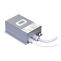
Elgo LIMAX Safe SC Operating Manual (84 pages)
Magnetic Absolute Shaft Information System with Safety Functions
Brand:
Elgo
| Category:
Measuring Instruments
| Size: 1.91 MB
Table of Contents
Table of Contents
3
1 General
8
Information Operating Manual
8
References
8
Terms and Abbreviations
8
Explanation of Symbols
10
Statement of Warranties
11
Demounting and Disposal
11
2 Safety
12
General Causes of Risk
12
Personal Protective Equipment
12
Conventional Use
13
3 Transport and Storage
14
Safety Instructions for Transport, Unpacking and Loading
14
Handling of Packaging Material
14
Inspection of Transport
14
Storage
14
4 Product Features
15
List of Figures
16
Figure 1: Type Label for Identification of the Safe Box
16
Figure 2: Info Label with Additional Information
16
Identification
16
Technical Data
16
Dimensions Safe Box
17
Figure 3: Safe Box Dimensions
17
Technical Data Safe Box
18
Additional Constraints for LIMAX Safe SC
20
Constraints for Use
20
General Constraints for LIMAX Safe SG/SC, 110 V / 230 V
20
Additional Constraints for LIMAX Safe SG
21
Prevention against External Door Contact Bridging
21
Special Constraints for 110 V Version
21
Special Constraints for 230 V Version
21
Figure 4: Neutral Conductor Connection to Avoid Door Contact Bridging by Indicator Circuit
22
Figure 5: PCB Layout to Avoid Door Contact Bridging by Indicator Circuit
22
Available Versions
23
Figure 6: Type Designation
23
Type Designation
23
List of Tables
26
Installation
24
Operating Area
24
Electrical Installation
25
Mechanical Installation
25
Table 1: Pin Assignment PIO Cable
26
Table 2: Pin Assignment SCA Cable
26
Figure 7: Installation Circuit Diagram for LIMAX Safe SC with (Semi-)Guided Sensor
27
Figure 8: Installation Circuit Diagram for LIMAX Safe SC with Unguided Sensor
28
Figure 9: Circuit Diagram of LIMAX Safe SG with (Semi)Guided Sensor, SGC Connected to an
29
Figure 10: Circuit Diagram of LIMAX Safe SG with Unguided Sensor, SGC Connected to an Electromechanically
30
Figure 11: Circuit Diagram of LIMAX Safe SG, SGC Connected to an Electromechanically Driven Safety Gear
31
Figure 12: Circuit Diagram of LIMAX Safe SG, SGC Connected to an Electromechanically Driven Safety Gear (Unguided Sensor)
32
Table 3: Wire Assignment of OC
33
Table 4: Wire Assignment of NOC and DCS
33
Figure 13: Example of an Installation Which Should be Avoided (Top) and an Advantageous Installation (Bottom)
34
Table 5: Wire Assignment Inspection Control
34
Figure 14: Connection Diagram for Power, CAN Communication and Reset Input
35
Table 6: Wire Assignment Power Supply and Battery Supply
35
Table 7: Wire Assignment Reset Input
35
Table 8: Wire Assignment of SGC Output und SGC-FB Input
35
Figure 15: SGC Integration Diagram for LIMAX Safe SG
36
Figure 16: SGC Integration Diagram for LIMAX Safe SC
36
Figure 17: Connection of Door Zone Indicator
37
Table 10: Wire Assignment CAN
37
Table 9: Wire Assignment Door Zone Indication
37
Check of Door Monitoring
38
Commissioning
38
Figure 18: Operation Modes
39
Operation Modes of the Safe Box
39
Learning of the Floor Image
40
Design and Functions 10.1 Basic Design
45
10 Design and Functions
45
Basic Design
45
Design and Functions 10.1 Basic Design
45
Figure 19: Components of the Safe Box
46
Guidelines for the Implementation in the Control
46
Safety Functions
48
Table 11: Overview Safety Functions
48
Check on Retardation
49
Over-Speed (Pre-Tripping / Final Tripping)
49
Table 12: Limit Switch Behavior
50
Limit Switches
50
Door Bridging
51
Figure 20: Behavior of the Upper Limit Switches
51
Unintended Car Movement (UCM)
51
Behavior of NOC (Informative)
52
Inspection / Inspection Limit Switches
52
Operating Modes
53
Table 13: Safety Output States in Pre-Commissioning Mode
53
Adjustment Mode
53
Learn Trip
53
Normal Mode
53
Pre-Commissioning
53
Protection of the Floor Table
53
Teach
53
Figure 21: LED Signals Visible through the Window
54
Signaling of the Safe Box
54
Table 14: Meaning of LED Signals
54
Optical Signaling
54
Connectors and Interfaces
55
Table 15: Wire Assignment Power Supply and Battery Supply
55
Table 16: Wire Assignment CAN
55
Acoustic Signaling
55
Assistance to the Teach Button
55
Canopen Interface
55
In Inspection Mode
55
Power Supply
55
Signaling Teach and Adjustment Mode
55
Door Contact Input
56
Inspection Control Connection
56
Safety-Relevant Actuators
56
Table 17: Wire Assignment of Safety Relevant Actuators
56
Table 18: Wire Assignment Door Contact Input
56
Table 19: Wire Assignment Inspection Control
56
Door Zone Indicator
57
Figure 22: Electrical Sensor Connection
57
Position Sensor Input
57
Reset Input
57
Table 20: Wire Assignment Door Zone Indication
57
Table 21: Wire Assignment Reset Input
57
Table 22: Pin Assignment Sensor Connector
57
11 During Operation
58
Relay Test
58
Readjusting the Floor Levels
59
Triggering the Safety Functions
59
Table 23: Triggering of the Safety Functions
60
Settable Parameters
62
Error Codes
63
Error Status Due to System Error
63
Reset to Delivery State
66
The Fault Register
66
Contact Test (Option)
68
Direct Relay Access (Option)
68
12 Safety Function Check
71
Correct Wiring Due to Type SG/SC
71
Door Monitoring and Capacitive Coupling
71
Examination of Door Switches and Locking Switches
71
Set Nominal Speed
71
Software Identification
71
Flush Positions of the Floors
72
Inspection Speed
72
Positions
72
Final Limit Switches
73
Inspection
73
Inspection Limit Switches
73
Deceleration Control Towards the Shaft End
74
Setting Error Level 4
74
Unintended Car Movement
74
Door Zone Indicator
75
Initial and Annual Examination of LIMAX33 RED/LIMAX44 RED
75
Malfunction of the SGC Feedback
75
Test of Motor Brake
75
Tripping of Safety Gear
75
Not Tested Safety Functions
76
13 Disturbances
77
Fault Clearance
77
Re-Start after Fault Clearance
78
14 Repairs / Maintenance
78
15 Replacing Components
79
Replacing LIMAX33 RED/LIMAX44 RED
79
Replacing Magnetic Tape
79
Replacing the Safe Box
79
16 Cleaning
80
A Over-Speed Curve Calculation
81
Figure 23: Dependency Final Tripping Speed as a Function of Rated Speed
81
Final Tripping Speed
81
Figure 24: Dependencies of Pre-Tripping and Final Tripping Speed as Functions of Rated Speed
82
Pre-Tripping Speed
82
Advertisement
Advertisement
Related Products
Elgo LIMAX33 CP-00 SERIES
Elgo LIMAX Safe SG
Elgo LIMAX1M Series
Elgo LIMAX44 RED
Elgo LIMAX2M Series
Elgo LIMAX33CP
Elgo EMAL Series
Elgo EMAX Series
Elgo Categories
Industrial Equipment
Irrigation System
Measuring Instruments
Fan
Lawn and Garden Equipment
More Elgo Manuals
Login
Sign In
OR
Sign in with Facebook
Sign in with Google
Upload manual
Upload from disk
Upload from URL