
Related Manuals for Elgo LIMAX Safe SG

Summary of Contents for Elgo LIMAX Safe SG
- Page 1 D-100988 / Rev. 9 / 2020-04-09 799000965 Operating Manual LIMAX Safe SG/SC Magnetic Absolute Shaft Information System with Safety Functions...
- Page 2 +49 (0) 7731 9339 – 0 +49 (0) 7731 2 13 11 support@elgo.de Document- No. D-100988 Document - Name LIMAX-SAFE-00-MA-E_15-20 Article Number 799000965 Document- Revision Rev. 9 Issue Date 2020-04-09 Copyright © 2020, ELGO Batscale AG - 2 -...
-
Page 3: Table Of Contents
Dimensions Safe Box ..................17 Technical Data Safe Box ..................18 Constraints for Use ................20 General constraints for LIMAX Safe SG/SC, 110 V / 230 V ........20 Additional constraints for LIMAX Safe SC............... 20 Additional constraints for LIMAX Safe SG .............. 21 Special constraints for 110 V Version .............. - Page 4 Contents Operation modes of the Safe Box ................ 39 Learning of the floor image ................40 Design and Functions ..............45 10.1 Basic Design ....................45 10.2 Guidelines for the Implementation in the Control ........... 46 10.3 Safety Functions ....................48 10.4 Operating Modes .....................
- Page 5 Contents Disturbances ..................77 13.1 Fault Clearance ....................77 13.2 Re-Start after Fault Clearance ................78 Repairs / Maintenance ..............78 Replacing Components ..............79 15.1 Replacing LIMAX33 RED/LIMAX44 RED ..............79 15.2 Replacing Magnetic Tape ................... 79 15.3 Replacing the Safe Box ..................79 Cleaning ...................
- Page 6 Figure 9: Circuit diagram of LIMAX Safe SG with (semi)guided sensor, SGC connected to an electromechanically driven blocking device on the speed governor ..........29 Figure 10: Circuit diagram of LIMAX Safe SG with unguided sensor, SGC connected to an electromechanically driven blocking device on the speed governor ................30 Figure 11: Circuit diagram of LIMAX Safe SG, SGC connected to an electromechanically driven safety gear (guided Sensor) ..........................
- Page 7 Contents Table 24: Settable parameter values ......................62 Table 25: Error codes ..........................63 - 7 -...
-
Page 8: General
Complete system (Safe Box, LIMAX33 RED/LIMAX44 RED and magnetic tape). A device may be a LIMAX Safe SG or a LIMAX Safe SC. The type of the device (SG or SC) cannot be changed. The type SG/SC is noted on the identification label. Some con- straints/hints/instructions for use are each only applicable for LIMAX Safe SG respectively LIMAX Safe SC. - Page 9 Suitably trained person entrusted with installation and commissioning of LIMAX Safe SG/SC or suitably trained person entrusted with troubleshooting Auditor Person of a notified body responsible for initial inspection of a lift where LIMAX Safe SG/SC is installed or responsible for the annual inspection Safety circuit...
-
Page 10: Explanation Of Symbols
General Explanation of Symbols Special notes in this manual are characterized by symbols. The notes are introduced by signal words which express the magnitude of danger. Please follow this advice and act carefully in order to avoid accidents and damage and injuries. Warning notes: DANGER! This symbol in connection with the signal word “Danger”... -
Page 11: Statement Of Warranties
At certain points it is necessary that the technician can read out certain internal values, which are received by the control via CANopen from LIMAX Safe SG/SC. If this is clear from the context, the control programmer must implement the ability to output these values in the lift control. -
Page 12: Safety
Safety 2 Safety CAUTION! Please read the operating manual carefully, before using the device! Observe the installation instructions! Only start up the device if you have understood the operating manual. The operating company is obliged to take appropriate safety measure. The initial operation may only be performed by qualified and trained staff. -
Page 13: Conventional Use
It is the responsibility of the manufacturer of a machine or installation to ensure the prop- er operation of the system. The ELGO-device is conceived only for the intended use described in this manual. The LIMAX Safe SG/SC - ELGO- length measuring system serves only to meas- ure lengths and to fulfil the safety functions in (see ... -
Page 14: Transport And Storage
Transport and Storage 3 Transport and Storage Safety Instructions for Transport, Unpacking and Loading CAUTION! Transport the package (box, palette etc.) professionally. Do not throw, hit or fold it. Handling of Packaging Material Notes for proper disposal: 1.6 Inspection of Transport Check the delivery immediately after the receipt for completeness and transport damage. -
Page 15: Product Features
The external elements are wired as described in chapter 8.3 to the corresponding inputs of LIMAX Safe SG/SC Nominal speed of the lift in which LIMAX Safe SG/SC is installed. The nominal speed is adjusted in the ... -
Page 16: Technical Data
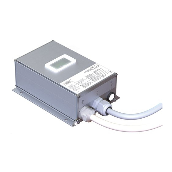
Furthermore, the type label contains the hardware and software versions, a unique, traceable device number (Serial No.), the production date (Batch No.) as well as (if available) the customer part number (Ident No./Type). When corresponding with ELGO always indicate this data. Figure 1: Type label for identification of the Safe Box Figure 2: Info label with additional information Concerning Figure 2, the rated speed (here: 4.0) and the “Brake type”... -
Page 17: Dimensions Safe Box
Technical Data Dimensions Safe Box Figure 3: Safe Box dimensions - 17 -... -
Page 18: Technical Data Safe Box
Technical Data Technical Data Safe Box LIMAX Safe SG/SC (General technical data) Mechanical Data Sensor LIMAX33 RED: 125 m / 262 m ( 6.4 Special constraints for 110 V Version) Maximum lifting height: Sensor LIMAX44 RED: 786 m (only for 230 V Version) - Page 19 0 … 150 VAC, max. 1 A Relay contact rating: SGC: 0 … 150 VAC, max. 1 A or 0 … 24 VDC, max. 1 A (only LIMAX Safe SG) LIMAX Safe SG/SC with 230 VAC safety circuit Safety circuit Voltage: 210 …...
-
Page 20: Constraints For Use
General constraints for LIMAX Safe SG/SC, 110 V / 230 V The general constraints for use of LIMAX Safe SG/SC (applicable for LIMAX Safe SG and for LIMAX Safe SC, each in both safety circuit variants (110 V / 230 V variant) are listed below. -
Page 21: Additional Constraints For Limax Safe Sg
(directly driven or indirectly driven by speed governor. The mechanical part driven by LIMAX Safe SG has to control a feedback switch. The switch has to be closed if the coil of the electromechanical part is energized. Otherwise the switch has to be open. -
Page 22: Figure 4: Neutral Conductor Connection To Avoid Door Contact Bridging By Indicator Circuit
Constraints for Use Safety circuit Indicator print Main contactors Indicator Current parallel to door contact in case neutral wire breaks Main contactors fall in case of neutral wire, OK! Indicator Assumed fault: : Break of neutral wire LIMAX Safe Input of door circuit „DCS“... -
Page 23: Type Designation
SBOX 1000 CO0TG Example: Version: = LIMAX Safe SG, safety circuit 230 VAC = LIMAX Safe SG, safety circuit 110 VAC = LIMAX Safe SC, safety circuit 230 VAC = LIMAX Safe SC, safety circuit 110 VAC (others: customer specific) Cable length: = 1.0 m... -
Page 24: Installation
In case of damage caused by failure to observe this operating manual, the warranty expires. ELGO is not liable for any secondary damage and for damage to persons, property or assets. The operator is obliged to take appropriate safety measures. The first start-up may only be performed by staff that has been trained and authorized by the operator. -
Page 25: Mechanical Installation
Before installing the Safe Box, the technician has to make sure that the nominal speed stated on the LIMAX Safe SG/SC type label matches the nominal speed of the elevator. If this is not the case, the Safe Box must not be used for this elevator. A Safe Box with matching nominal speed has to be acquired instead. -
Page 26: Table 1: Pin Assignment Pio Cable
Installation 8.3.3 Options regarding plugs/wire ends In case of cable-option plug type “ZP 2.5/1AN/24“ (of Weidmüller company), the connection numbers in the figures (designated as connector S99) have the functions as documented below. In case of “open wire ends” follow cable designation (see 10.1) and colours of wires. Table 1: Pin assignment PIO cable Table 2: Pin assignment SCA cable Wire colour... -
Page 27: Figure 7: Installation Circuit Diagram For Limax Safe Sc With (Semi-)Guided Sensor
Installation 8.3.4 Overview of the electrical installation of LIMAX Safe SC Attention! The following diagram is only applicale for LIMAX Safe SC: AC supply of Safety circuit Ins pection sw itch Power supply Battery 24 V 12 V 0 V Ins pection Upper Ins pection... -
Page 28: Figure 8: Installation Circuit Diagram For Limax Safe Sc With Unguided Sensor
Installation Attention! The following diagram is only applicale for LIMAX Safe SC: AC supply of Safety circuit Ins pection sw itch Power supply Battery 24 V 12 V 0 V Ins pection Ins pection DOW N Re call HW: 02.1 HW: 00.1 SW: xx xxx x SW: xx xxx x... -
Page 29: Figure 9: Circuit Diagram Of Limax Safe Sg With (Semi)Guided Sensor, Sgc Connected To An
TO RE SET button in the machin e room On ly n on safety relevan t functions (not defin ed yet) Figure 9: Circuit diagram of LIMAX Safe SG with (semi)guided sensor, SGC connected to an electromechanically driven blocking device on the speed governor - 29 -... -
Page 30: Figure 10: Circuit Diagram Of Limax Safe Sg With Unguided Sensor, Sgc Connected To An Electromechanically
TO RE SET button in the machin e room On ly n on safety relevan t functions (not defin ed yet) Figure 10: Circuit diagram of LIMAX Safe SG with unguided sensor, SGC connected to an electromechanically driven block- ing device on the speed governor - 30 -... -
Page 31: Figure 11: Circuit Diagram Of Limax Safe Sg, Sgc Connected To An Electromechanically Driven Safety Gear
Th is is on ly a s ymbolic drawing! Th e safety gear its elf is not part of th e certification Figure 11: Circuit diagram of LIMAX Safe SG, SGC connected to an electromechanically driven safety gear (guided Sensor) - 31 -... -
Page 32: Figure 12: Circuit Diagram Of Limax Safe Sg, Sgc Connected To An Electromechanically Driven Safety Gear (Unguided Sensor)
Th is is on ly a s ymbolic drawing! Th e safety gear its elf is not part of th e certification Figure 12: Circuit diagram of LIMAX Safe SG, SGC connected to an electromechanically driven safety gear (unguided Sen- sor) - 32 -... -
Page 33: Table 3: Wire Assignment Of Oc
Instead it is used as DCS-L input for LIMAX Safe SG/SC. The neutral wire of the safety circuit has to be connected to LIMAX Safe SG/SC (to DCS-N) as well. -
Page 34: Figure 13: Example Of An Installation Which Should Be Avoided (Top) And An Advantageous Installation (Bottom)
8.3.9 Connection of inspection control‘s signals The 24 V level of the inspection control has to be connected to the LIMAX Safe SG/SC as described in Table 5. The connection of the inspection control to the safety circuit remains unchanged. -
Page 35: Figure 14: Connection Diagram For Power, Can Communication And Reset Input
8.3.10 Connection of power supply and emergency power supply The 24 V supply for LIMAX Safe SG/SC is powered by an external 24 V power supply. To use the door zone indicator function additionally a 12 V battery has to be connected. -
Page 36: Figure 15: Sgc Integration Diagram For Limax Safe Sg
LIMAX Safe SG, e.g. in order to fulfill EN81-20 §5.6.2.2.1.1.a.). It doesn’t matter if the user must choose a LIMAX Safe SG (because of no A3 Brake available) or if it is the free decision of the user to use the LIMAX Safe SG: In any case of LIMAX Safe SG is used, the connection of SGC-IN, SGC-OUT and SGC-FB has to be carried out according to Figure 9 to Figure 12 and Figure 15. -
Page 37: Figure 17: Connection Of Door Zone Indicator
8.3.14 Connection CAN bus The LIMAX Safe SG/SC CAN bus connection CAN High and CAN Low is connected to the CAN bus of the con- trol. The shield may be optionally connected to protection earth on the side of the lift control. See Figure 14 for further details. -
Page 38: Commissioning
LIMAX Safe SG/SC , even if the doors are closed. When lift is switched to recall and a direction button is pressed on the recall panel, the open is bridged. -
Page 39: Operation Modes Of The Safe Box
Commissioning Operation modes of the Safe Box There are the following operation modes: Pre-commissioning mode, delivery status. There is no shaft image available. OC disconnects the safety circuit. It is only possible to travel with recall. Teach mode: The Safe Box can learn the shaft image in this mode. First it is only possible to travel with ... -
Page 40: Learning Of The Floor Image
If the floor image of LIMAX Safe SG/SC is not empty (normal mode) and the floor image is to be learned again (e.g. because a new floor was added), the technician carries out the transition into teach mode in an identical manner as from the pre-commissioning mode (described above). - Page 41 (see chapter 8.3.7 for further explanations). SGC is closed and so the blocking of the speed governor/the safety gear is released in case of LIMAX Safe SG. In case of LIMAX Safe SC the second spot of absolute separation of the safety circuit by SGC is closed. OC is opened.
- Page 42 When LIMAX Safe SG/SC detects a system error ( 11.5, 11.6) in teach mode, the teach mode is left imme- diately and any floor positions that were already learned are erased. After clearing and resetting the error LIMAX Safe SG/SC is in pre-commissioning mode and teaching has to be started over.
- Page 43 as closed or if the door circuit really is regarded as closed, they are set to zero. Test failed. Via CANopen, the control hast to read out the diagnostic values from LIMAX Safe SG/SC: Object 2159h, sub-index 0Dh: ...
- Page 44 If this test failed, the reason for the high capacitive coupling has to be found and removed before the lift can be operated. If the above test was performed successfully, regarding LIMAX Safe SG/SC the lift is now ready for operation and the initial inspection by the notified body, see chapter 12.
-
Page 45: Design And Functions
Position Sensor input ....................... 57 10.1 Basic Design LIMAX Safe SG/SC consists of the position sensor LIMAX33 RED/LIMAX44 RED, the magnetic tape and the Safe Box. The LIMAX33 RED/LIMAX44 RED in combination with the magnetic tape is a position measuring system. -
Page 46: Guidelines For The Implementation In The Control
10.2 Guidelines for the Implementation in the Control There is a close connection between LIMAX Safe SG/SC and the lift control, which is part of the safety concept. Without this connection, LIMAX Safe SG/SC does not work. Communication between control and LIMAX Safe SG/SC is carried out via a CAN bus and follows the protocol as specified in ... - Page 47 Item 7.) in the above list only relates to the reading of data from the LIMAX Safe SG/SC. This requires no condi- tions for the training of the technician, as long as the technician does not initiate further corrective action.
-
Page 48: Safety Functions
X in column “During commissioning”. After correct installation and commission- ing (LIMAX Safe SG/SC is in Normal or Adjustment mode, 9.2), LIMAX Safe SG/SC fulfils the safety functions marked with X in column “Normal Mode”:... -
Page 49: Over-Speed (Pre-Tripping / Final Tripping)
§5.3.9.2 door circuit and cuts SC by NOC. 10. Inspection Additional func- LIMAX Safe SG/SC cuts the SC if tion, no refer- inspection switch is set to inspec- ence to the tion (in addition to the cut of SC... -
Page 50: Table 12: Limit Switch Behavior
Design and Functions 10.3.3 Limit Switches This chapter shows an overview of the reactions of the final limit switches (safety function 5, see 10.3 ) and the inspection limit switches (safety function 6, see 10.3) under various conditions. The table below describes the behavior of the limit switches in relation to operating mode and car position. -
Page 51: Figure 20: Behavior Of The Upper Limit Switches
Design and Functions Upper limit switches behavior Closed final limit switch Open Normal and adjustment mode Closed inspection limit switch Open Pos. highest floor Closed limit switches, temp. ref. position not set yet Open Closed Teach mode final limit switch, temp. -
Page 52: Inspection / Inspection Limit Switches
If lower inspection limit switch is over travelled, OC/NOC will only close if UP button is pushed. LIMAX Safe SG/SC supervises also the consistency of direction Button and real moving direction: If the UP button is pushed and car travels upwards, OC and NOC will open. -
Page 53: Operating Modes
In order to prevent an accidental change of floor positions, the corresponding CAN messages are secured by a specific key word. The data field of the CAN message contains this key word. LIMAX Safe SG/SC will only ac- cept the CAN message if the key word is correct. -
Page 54: Signaling Of The Safe Box
Position of LIMAX Safe SG/SC is within a known door zone. The size depends on the levelling zone size. LIMAX Safe SG/SC is elsewhere in the shaft or no floors were learned. The status in bold define the faultless normal operation The CANopen LEDS ERR and RUN are according to ... -
Page 55: Connectors And Interfaces
Design and Functions 10.5.2 Acoustic signaling There is an acoustic signaling by buzzer signal. This serves three purposes described in the following sections. 10.5.2.1 In inspection mode If during inspection trip the position approaches inspection limit switches, the Safe Box emits continuous short acoustic signals. -
Page 56: Table 17: Wire Assignment Of Safety Relevant Actuators
10.6.4 Door contact input LIMAX Safe SG/SC uses the end of the door circuit as an input to detect open doors. The input consists of two wire connections, one for neutral conductor and one for the signal at the end of the door circuit. -
Page 57: Figure 22: Electrical Sensor Connection
Design and Functions 10.6.6 Door zone indicator Signalling of door zones takes place by means of a potential free contact between DZ-SUP and DZ. There must be provided an external power supply (12 V or 24 V battery) to DZ-SUP to use this contact. This output is only for indication. -
Page 58: During Operation
CAN message) to carry out the test ( /CO_SPECS/). In case 11 h 50 min elapsed since last relay test LIMAX Safe SG/SC decides on his own when there is a suitable moment to carry out the test (at next standstill). -
Page 59: Readjusting The Floor Levels
(by car call). 11. The technician signals to the lift control that the respective floor is to be adjusted in LIMAX Safe SG/SC; the floor number is fed in with the signal (numbering from bottom to top starting with 1 for the lowest floor).The door must be open and the cabin must be at a standstill. -
Page 60: Table 23: Triggering Of The Safety Functions
During operation Table 23: Triggering of the safety functions Safety Opening contacts and condition for Reset of safe- Hints for emergency evacuation function triggering ty function Over-speed Manual error If persons are trapped in the cabin, the cabin (pre-tripping) Opens if pre tripping speed of Safe Box is exceed- reset. - Page 61 For those safety functions, the error state is kept stored in a non-volatile way. That means that even after LIMAX Safe SG/SC was switched off and then back on the contacts specified for the safety function remain open.
-
Page 62: Settable Parameters
During operation NOTE! (Applies only for LIMAX Safe SG): In case of a power failure all actuator contacts will open and therefore the blocking device of the speed governor or the safety gear is triggered. The customer is responsible to take measures against unnecessary blocking of the safety gear by use of an for example. -
Page 63: Error Status Due To System Error
When the self-diagnostic function detects a defect, the Safe Box sets an error level which is defined for the diag- nosed defect. The actuator response depends on the respective error level: Level 1: If the car is moving LIMAX Safe SG/SC ends the travel and changes the error level to level 2 as soon as standstill is reached. - Page 64 During operation Error code Meaning of the Error Error Meaning of special errors Meaning for technician group group codes level 104h Some position errors Resetting the error without additional appeared measures is allowed but this is not recommended because it is very likely that the error will appear again.
- Page 65 The number of floors must match. The floor positions stored in LIMAX Safe SG/SC and in the control must match with a tolerance of 50mm. If this is not the case, correct the floor table of the control or LIMAX Safe SG/SC.
-
Page 66: Reset To Delivery State
So this error blocks the normal reset. A total reset as described above followed by a new teaching of the Safe Box is necessary. If total reset takes place while LIMAX Safe SG/SC is in teach or adjustment mode, these modes are left at once. After total reset LIMAX Safe SG/SC is always in pre-commissioning mode. - Page 67 During operation b.) The actual moving direction while inspection trip contradicts the direction demanded through the direc- tion buttons. This function is reset if both direction buttons are released for 10s. In this case the cabling to the inspection control has to be checked. You can find a detailed description of the fault register in the CANopen specifications (...
-
Page 68: Direct Relay Access (Option)
Set the lift in a safe state by control in case control states that there is a problem Other reasons, e.g. energy safe if lift is in standby (power consumption of LIMAX Safe SG/SC is greatly reduced when relays are de-energised) 11.10 Contact Test (Option) - Page 69 SG/SC also about if the prerequisites for the contact test are fulfilled or not. If control is remembered by LIMAX Safe SG/SC that a contact test should be done, control will stop the car at a floor and keep doors closed. So door circuit should normally be detected as closed by LIMAX Safe SG/SC. Con- trol now sends LIMAX Safe SG/SC a demand to carry out the test.
- Page 70 - If a demand to go to recall is received within these 2 seconds, no error would be set. - If no demand to go to recall is received, LIMAX Safe SG/SC will set the error. This delay of 2 s is only active if there is no inspection.
-
Page 71: Safety Function Check
12.5 Set Nominal Speed The nominal of LIMAX Safe SG/SC is noted on the specifications plate. It must fit the nominal speed of the lift. The nominal speed of the Safe Box has to be read out via CANopen. It must also match the speed noted on the plate. -
Page 72: Flush Positions Of The Floors
Safety Function Check 12.6 Flush Positions of the Floors The lift is made to travel to one floor after the other by car calls and the doors are opened at each floor level. It is examined, if the respective door thresholds are aligned. Check if the door thresholds are flush. This is to make sure that the floor positions in the control are correct. -
Page 73: Final Limit Switches
First, the auditor displays the offsets for the top and the bottom final limit switches, see chapter 11.4. The auditor also displays the positions of the highest and lowest floors stored in LIMAX Safe SG/SC. With this infor- mation, the auditor calculates the position of the lower and upper final limit switches. -
Page 74: Setting Error Level 4
At the beginning of the test procedure, the cabin is at a floor level and the lift-system is switched free of voltage. The end of the door circuit is disconnected from the door input of LIMAX Safe SG/SC “DCS-L” and is insulated to avoid any unintended contact with conductive parts or humans. -
Page 75: Malfunction Of The Sgc Feedback
LIMAX Safe SG provides the possibility to open SGC by CANopen explicitly. This function may help in order to test the safety gear. This is not a test of LIMAX Safe SG itself but it may be a convenient way to test the safety gear for the auditor. -
Page 76: Not Tested Safety Functions
The correct reaction of the contacts OC, NOC and SGC is also proved by specific tests. For every contact, at least once the correct status change was verified. Moreover, LIMAX Safe SG/SC is designed and built according to the principles of functional safety. Any error in the actuators would be detected by the self-diagnosis function. -
Page 77: Disturbances
Disturbances 13 Disturbances This chapter describes possible causes for disturbances and measures for their removal. In case of increased disturbances, please follow the measures for fault clearance in chapter 13.1. In case of disturbances that cannot be eliminated by following the advice and the fault clearance measures giv- en here, please contact the manufacturer (see second page). -
Page 78: Re-Start After Fault Clearance
Repairs / Maintenance 13.2 Re-Start after Fault Clearance After the fault clearance: 1. Reset the emergency stop mechanism if necessary 2. Reset the error report at the super-ordinate system if necessary. 3. Ensure that there are no persons in the danger area. 4. -
Page 79: Replacing Components
LIMAX Safe SG/SC must be switched off if the sensor is to be electrically separated from the Safe Box. Other- wise, damage to the Safe Box and/or the sensor cannot be ruled out. -
Page 80: Cleaning
At the moment, the latter can be ensured only at ELGO Batscale AG. The dismounted Box has to be sent back to ELGO Batscale AG. There it will be reset and it will be checked if all safety relevant values (shaft image and temporary reference positions) are really erased. -
Page 81: A Over-Speed Curve Calculation
Over-speed Curve Calculation A Over-speed Curve Calculation The pre-tripping- and final tripping speed is calculated from nominal speed as described in this chapter. A.1 Final tripping speed The calculation of final tripping speed defined in four sections. Nominal rated speed [mm/s] Section Calculation from... -
Page 82: Pre-Tripping Speed
Over-speed Curve Calculation A.2 Pre-tripping speed The calculation of pre-tripping speed is also defined in three sections as follows. Nominal rated speed [mm/s] Section Calculation from 400 constantly 600 mm/s 1000 �� + 233 (all in mm/s) = 0.9166 ⋅ �� ��������... - Page 83 Index Index Abbreviations ............ 8 Mechanical Installation ........25 Accident prevention regulations......8 Operating area ..........24 Acoustic signaling ..........55 Operating Modes ..........53 Activation of teach mode ........40 Operation modes of the Safe Box ..... 39 Available versions ..........23 Operational safety ..........
- Page 84 F ö h r e n w e g 2 0 , F L - 9 4 9 6 B a l z e r s Subject to change - © 2020 Fon.:+423 (0) 380 02 22, Fax.:+423 (0) 380 02 24 ELGO Batscale AG Internet: www.elgo.li, Mail: info@elgo.li - 84 -...
Need help?
Do you have a question about the LIMAX Safe SG and is the answer not in the manual?
Questions and answers