Sign In
Upload
Manuals
Brands
DIEBOLD NIXDORF Manuals
Touch terminals
100D FL
DIEBOLD NIXDORF 100D FL Manuals
Manuals and User Guides for DIEBOLD NIXDORF 100D FL. We have
2
DIEBOLD NIXDORF 100D FL manuals available for free PDF download: Installation Manual, Operating Manual
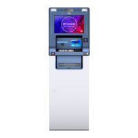
DIEBOLD NIXDORF 100D FL Installation Manual (98 pages)
Brand:
DIEBOLD NIXDORF
| Category:
Touch terminals
| Size: 5.54 MB
Table of Contents
Table of Contents
2
1 Introduction
6
Symbols Used in this Manual
6
Section-Specific Warning Notes
7
2 Safety
8
Characters, Labels and Symbols
8
General Safety Precautions for the System
9
Notes Concerning Installation
12
3 Planning the Installation
13
System Dimensions
13
Frontload UL Safe 4H
13
Illustration 3-1 System Dimensions - Frontload UL Safe 4H
13
Frontload UL Safe 5H
14
Illustration 3-2 System Dimensions - Frontload UL Safe 5H
14
Frontload CEN Safe
15
Illustration 3-3 System Dimensions - Frontload CEN Safe
15
Overview of Installation Types
16
Dimensions of Cable Lead-Ins into the Safe
16
Frontload UL Safe
16
Illustration 3-4 Dimensions of Cable Lead-Ins for Frontload UL Safe
16
Frontload CEN Safe
17
Illustration 3-5 Rear Cable Lead-In - Frontload CEN Safe
17
Installation Options of System Versions
18
Perspective View UL Safe 4H (Free-Standing)
18
Illustration 3-6 Frontload UL Safe 4H
18
Perspective View UL Safe 5H (Free-Standing)
19
Illustration 3-7 Frontload UL Safe 5H
19
Perspective View CEN Safe (Free-Standing)
20
Illustration 3-8 Frontload CEN Safe
20
Position of Safe
21
Illustration 3-9 Position of UL Safe
21
Illustration 3-10 Position of CEN Safe
22
Ventilation Opening
23
Illustration 3-11 Ventilation Openings
23
Storage if Construction Work Is Not yet Complete
24
Space Required for Operation and Maintenance
25
Frontload Version with UL Safe
25
Illustration 3-12 Space Required for Operation and Maintenance, Frontload System with UL Safe
25
Frontload Version with CEN Safe
26
Illustration 3-13 Space Required for Operating and Maintenance, Frontload System with CEN Safe
26
Floor Space Requirements
27
Load-Carrying Capacity
27
Notes on Floor Mounting
27
Tear-Off Resistance in Compliance with Vds and en 1143-1 Guidelines
28
Mounting Without Installation Frames
29
General Information
29
Dimensions of the Safe Attachment Points
30
Illustration 3-14 Dimensions of Safe Attachment Points for Frontload UL Safe
30
Illustration 3-15 Dimensions of Safe Attachment Points for Frontload CEN Safe
31
Dimensions of Cable Lead-Ins
32
Illustration 3-16 Dimensions of Cable Lead-Ins for Frontload UL Safe
32
Illustration 3-17 Dimensions of Cable Lead-Ins for Frontload CEN Safe
33
Tear-Off Sensor
34
Drilling Diagrams
35
Drilling Diagram: Frontload UL Safe
35
Illustration 3-18 Drilling Template for Device with UL Safe (Frontload)
35
Drilling Diagram: Frontload CEN Safe
36
Illustration 3-19 Drilling Template for (Frontload) Device with CEN Safe
36
Network and Data Cables
37
Power Supply
38
Remote Status Indicator
39
Cable Lead-Ins into in the Safe
40
Rear Cable Lead-In - Frontload
40
Illustration 3-20 Cable Lead-In into the Safe from the Rear
40
Transport Route Requirements
41
Transport Dimensions UL Safe Frontload
42
Illustration 3-21 Transport Dimensions of the Frontload Wooden Shipping Pallet, 4H UL Safe
42
Illustration 3-22 Transport Dimensions of the Frontload Wooden Shipping Pallet, 5H UL Safe
43
Illustration 3-23 Transport Dimensions of the Frontload Metal Shipping Bracket, 4H UL Safe
44
Illustration 3-24 Transport Dimensions of the Frontload Metal Shipping Bracket, 5H UL Safe
45
Illustration 3-25 Transport Dimensions of UL Safe Frontload
46
Illustration 3-26 Minimum Transport Dimensions UL Safe Frontload
47
Transport Dimensions CEN Safe Frontload
48
Illustration 3-27 Transport Dimensions of the Frontload Wooden Shipping Pallet, CEN Safe
48
Illustration 3-28 Transport Dimensions of the Frontload Metal Shipping Bracket, CEN Safe
49
Illustration 3-29 Transport Dimensions CEN Safe Frontload
50
Illustration 3-30 Minimum Transport Dimensions CEN Safe Frontload
51
4 Installation
52
Removing the Transport Packing
52
Disassembly of Wooden Shipping Pallet
53
Illustration 4-1 Wooden Shipping Pallet - Only Shift in the Directions Indicated
53
Illustration 4-2 Shipping Pallet - Removing Screws
54
Illustration 4-3 Shipping Pallet - Removing from the System
55
Disassembly of Metal Shipping Bracket
56
Illustration 4-4 Metal Shipping Bracket - Only Shift in the Directions Indicated
56
Illustration 4-5 Shipping Bracket - Removing Screws
57
Illustration 4-6 Shipping Bracket - Removing from the System
58
Removal of Shipping Restraints
59
TP30/TP31 Receipt Printer
61
Removal of AFD to Install Anchor Bolts
62
Mounting Sets
64
Mounting Sets (Optional)
64
Mounting Set (for UL Safe)
64
Mounting Set (for CEN Safe)
64
Mounting Set (Expansion Anchor Set)
64
Overview of Installation Types
65
Mounting the Device
66
Illustration 4-7 Mounting Structure Without Installation Frame
66
Illustration 4-8 Installation with Mounting Anchors-Marking out Bore Holes
67
Illustration 4-9 Installation with Mounting Anchors-Drilling Bore Holes
67
Illustration 4-10 Installation with Mounting Anchors-Aligning the System
68
Illustration 4-11 Installation with Mounting Anchors- Securing the System
68
Installation Without Frame
70
Putting into Service
70
Access the Relay Panel for External Features (Frontload)
71
Installing the 'Remote Status Indicator
72
Remote Status Indicator' - Standard
72
Remote Status Indicator' - Audio
77
Shortening Cable Ends
82
5 Appendix
88
Checklist for Installation Preparations
88
Technical Data
92
General Installation Conditions
92
Environmental Conditions
94
Compliance with Standards and Approvals
95
Environmental Protection
96
Advertisement
DIEBOLD NIXDORF 100D FL Operating Manual (58 pages)
Brand:
DIEBOLD NIXDORF
| Category:
Cash Counter
| Size: 2.85 MB
Table of Contents
Table of Contents
2
Legal Disclaimer
5
Safety
6
Important Safety Precaution
6
Notes Concerning Installation
6
General Safety Precautions
6
Introduction
9
Symbols Used in this Manual
9
General Power Interruption
9
DN Series 100D FL
10
Device Overview
12
System Types
12
DN Series 100D Frontload
12
Controls
13
Frontload Overall View
13
Fascia
14
Component Carrier Pulled out
15
Fascia Opened
16
Front Door Opened
17
Safe Opened
18
General Information
22
Calling the Product-Specific Software
22
Frontload
23
Opening/Closing the System Doors
23
DN Series 100D Frontload
24
Opening/Closing the Safe Door
30
Opening/Closing the Safe Door (with Factory Setting)
30
Customizing the Key and Number Combination Locks
37
Opening/Closing the Safe Door (with Customized Lock)
42
Opening the Safe Door (with Customized Lock)
42
Closing the Safe Door (with Customized Lock)
46
Switching the System on
48
Frontload
49
Switching the System off
50
Frontload
51
Setting the Volume of the Headphone Jack
52
Remote Status Indicator
53
TP30/TP31 Receipt Printer
55
Servicing the TP30/TP31 Receipt Printer
55
TP29 Journal Printer
55
Problems
56
General Information
56
Advertisement
Related Products
DIEBOLD NIXDORF BEETLE /iPOS plus SL
DIEBOLD NIXDORF BEETLE /iPOS plus XL
DIEBOLD NIXDORF BEETLE /iSCAN EASY eXpress+
DIEBOLD NIXDORF BEETLE /iSCAN EASY Non Cash
DIEBOLD NIXDORF BEETLE /XS
DIEBOLD NIXDORF BEETLE A Series
DIEBOLD NIXDORF BEETLE A1 50 Series
DIEBOLD NIXDORF BEETLE A1 70 Series
DIEBOLD NIXDORF BEETLE A1050
DIEBOLD NIXDORF BEETLE A1070
DIEBOLD NIXDORF Categories
Touch terminals
Monitor
Cash Counter
Printer
Motherboard
More DIEBOLD NIXDORF Manuals
Login
Sign In
OR
Sign in with Facebook
Sign in with Google
Upload manual
Upload from disk
Upload from URL