Sign In
Upload
Manuals
Brands
Delta Manuals
Controller
ASD-B2-1021-B
Delta ASD-B2-1021-B Manuals
Manuals and User Guides for Delta ASD-B2-1021-B. We have
2
Delta ASD-B2-1021-B manuals available for free PDF download: User Manual
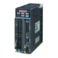
Delta ASD-B2-1021-B User Manual (314 pages)
ASDA-B2 series Standard Type AC Servo Drive for Network Communication Application
Brand:
Delta
| Category:
Controller
| Size: 8.27 MB
Table of Contents
Revision June
2
Table of Contents
6
Technical Support and Service
12
Unpacking Check
14
User Information
12
Chapter 1 Unpacking Check and Model Explanation
14
Model Explanation
15
Nameplate Information
15
Nameplate Explanation
15
Serial Number Explanation
15
Model Name Explanation
16
ECMA Series Servo Motor
17
Servo Drive and Servo Motor Combinations
18
Servo Drive Features
19
Control Modes of Servo Drive
20
Installation and Storage
22
Installation Notes
22
Storage Conditions
22
Chapter 2 Installation and Storage
22
Installation Conditions
23
Operating Temperature
23
Drive Mounting
24
Motor Mounting
24
Installation Procedure and Minimum Clearances
24
Side by Side Installation
25
Molded-Case Circuit Breaker and Fuse Current Recommended Value
26
EMI Filter Selection
27
General Precaution
27
Choose Suitable Motor Cable and Precautions
28
Dimensions
29
Regenerative Resistor
30
Built-In Regenerative Resistor
30
Built-In Regenerative Resistor Specifications
30
External Regenerative Resistor
31
Regenerative Power Calculation Method
31
Without Load
31
Simple Calculation Method
34
Connecting to Peripheral Devices
38
Connections and Wiring
38
Chapter 3 Connections and Wiring
38
Servo Drive Connectors and Terminals
39
Wiring Notes
41
Wiring Methods
42
Single-Phase Power Supply
42
Three-Phase Power Supply
43
Motor Power Cable Connector Specifications
44
Encoder Connector Specifications
46
Cable Specifications for Servo Drive
47
Basic Wiring
49
Input / Output Interface Connector - CN1
53
CN1 Terminal Identification
53
The Layout of CN1 Drive Connector
53
CN1 Terminal Signal Identification
54
Signals Explanation of Connector CN1
55
Signals Explanation of Connector CN5
56
DO Signals
57
DI Signals
58
Source of Speed Command
60
Source of Torque Command
60
Default DI Signals and Control Modes
61
Default DO Signals and Control Modes
62
Wiring Diagrams of I/O Signals (CN1)
64
Speed / Torque Analog Signal Input
64
Analog Monitor Output
64
User-Defined DI and DO Signals
69
Encoder Connector CN2
70
The Layout of CN2 Drive Connector
70
The Layout of CN2 Motor Connector
70
CN2 Terminal Signal Identification
70
Serial Communication Connector CN3
71
CN3 Terminal Layout and Identification
71
CN3 Terminal Signal Identification
71
Connection between PC and Connector CN3
72
Standard Connection Example
73
Speed Control Mode
74
Torque Control Mode
75
Description of Digital Keypad
76
Chapter 4 Display and Operation
76
Display Flowchart
77
Keypad Operation
77
Status Display
78
Save Setting Display
78
Fault Message Display
78
Polarity Setting Display
78
Monitor Setting Display
79
General Function Operation
82
Fault Code Display Operation
82
JOG Operation
83
Force Output Control Operation
84
DI Diagnosis Operation
85
DO Diagnosis Operation
86
Inspection Without Load
88
Chapter 5 Trial Run and Tuning Procedure
88
Applying Power to the Drive
90
Main Circuit Wiring
90
Turn the Power on
90
Over Voltage
91
Encoder Error
91
Reverse Limit Switch Error
92
Forward Limit Switch Error
92
Overcurrent
93
Undervoltage
93
JOG Trial Run Without Load
94
Speed Trial Run Without Load
96
Tuning Procedure
98
Tuning Flowchart
99
Load Inertia Estimation Flowchart
100
Auto Mode Tuning Flowchart
101
Semi-Auto Mode Tuning Flowchart
102
Limit of Load Inertia Estimation
104
Mechanical Resonance Suppression Method
106
Relationship between Tuning Modes and Parameters
107
Gain Adjustment in Manual Mode
108
KVP, Parameter P2-04 Proportional Speed Loop Gain
108
KPP, Parameter P2-00 Proportional Position Loop Gain
108
KVI, Parameter P2-06 Speed Integral Compensation
109
DST, Parameter P2-26 External Anti-Interference Gain
109
PFG, Parameter P2-02 Position Feed Forward Gain
109
Control Modes of Operation
110
Chapter 6 Control Modes of Operation
110
Position Control Mode
111
Command Source of Position (PT) Control Mode
111
Structure of Position Control Mode
113
Electronic Gear Ratio
114
Pulse Inhibit Input Function (INHP)
114
Electronic Gear Ratio (1St Numerator) (N1)
114
Electronic Gear Ratio (Denominator)
114
Electronic Gear Ratio
115
Low-Pass Filter
116
Smooth Constant of Position Command
116
Position Loop Gain Adjustment
116
Proportional Position Loop Gain
117
Position Feed Forward Gain
117
Command Source of Speed Control Mode
119
Manual Mode
119
Auto Mode
119
Structure of Speed Control Mode
120
Smoothing Strategy of Speed Control Mode
121
S-Curve Filter
121
Acceleration Time
122
Deceleration Time
123
Accel /Decel S-Curve
123
Analog Speed Command S-Curve Filter
124
Analog Speed Command Low-Pass Filter
124
Analog Speed Input Scaling
125
Max. Analog Speed Command / Limit
126
Timing Chart of Speed Control Mode
126
Speed Loop Gain Adjustment
127
Tuning Mode Selection
127
Explanation of Manual Mode
128
Explanation of Auto-Tuning Mode
128
Explanation of Semi-Auto Tuning Mode
128
Proportional Speed Loop Gain
129
Speed Integral Compensation
129
Speed Feed Forward Gain
129
Frequency Domain
130
Time Domain
131
Speed
131
Auto Mode (Continuous Adjustment))
132
Resonance Suppression
133
Notch Filter 1 (Resonance Suppression)
133
Notch Filter Attenuation Rate 1
133
Notch Filter 2 (Resonance Suppression)
134
Notch Filter Attenuation Rate 2
134
Notch Filter 3 (Resonance Suppression)
134
Notch Filter Attenuation Rate 3
135
Low-Pass Filter Time Constant
135
Settings of P2-47
137
Flowchart of Auto Resonance Suppression Operation
137
Use Notch Filter to Suppress Resonance
139
Use Low-Pass Filter to Suppress Resonance
139
Command Source of Torque Control Mode
140
Torque Command Sources
140
Structure of Torque Control Mode
141
Smoothing Strategy of Torque Control Mode
142
Analog Torque Input Scaling
142
Max. Analog Torque Command / Limit
143
Timing Chart of Torque Control Mode
143
Control Mode Selection
144
Speed / Position Control Mode Selection
144
Speed / Torque Control Mode Selection
145
Torque / Position Control Mode Selection
145
PT-T Mode
145
Others
146
Speed Limit
146
Torque Limit
146
Analog Monitor
147
Pulse Output Polarity Setting
148
Analog Monitor Output Proportion 1(CH1)
148
Analog Monitor Output Proportion 2(CH2)
148
Analog Monitor Output Drift Adjustment
149
Electromagnetic Brake
150
BRKR Output Timing Explanation
151
Electromagnetic Brake Wiring Diagram
151
Servo Parameters
154
Definition
154
Abbreviation of Control Modes
154
Explanation of Symbols (Marked after Parameter)
154
Chapter 7 Parameters
154
Monitor and General Use
155
Parameters Summary
155
Digital I/O and Relative Input Output Setting
161
Communication
162
Diagnosis
163
Detailed Parameter Listings
164
Drive Fault Code
164
Firmware Version
164
Drive Status (Front Panel Display)
165
Servo Startup Time
167
Status Monitor 1
167
Status Monitor 2
168
Status Monitor 3
168
Status Monitor 4
169
Status Monitor Selection 2
170
Status Monitor Selection 3
170
Status Monitor Register
171
Status Monitor Register Selection
171
Servo Output Status Display
172
External Pulse Input Type
173
P1-XX Basic Parameters
173
Input Polarity
174
Source of Pulse Command
174
Control Mode and Output Direction
175
Control Mode Settings
175
Single Mode
175
Speed and Torque Limit
176
Sz: Zero Speed / Internal Speed Command
176
Tz: Zero Torque / Internal Torque Command
176
1St Speed Command or Limit
179
2Nd Speed Command or Limit
179
3Rd Speed Command or Limit
179
1St Torque Command or Limit
180
2Nd Torque Command or Limit
180
3Rd Torque Command or Limit
181
Motor Stop Mode Selection
181
Electronic Gear Ratio (Denominator) (M)
187
Encoder Output Pulse Number
188
Speed Reached Output Range
189
Positioning Completed Width
190
Regenerative Resistor Capacity
190
Regenerative Resistor Value
190
Maximum Speed Limit
191
Output Overload Warning Time
191
Analog Speed Linear Filter (Moving Filter)
192
Motor Protection Percentage
192
Motor Protection Time
192
Friction Compensation Percentage
193
Friction Compensation Smooth Constant
194
Position Command Moving Filter
194
Max. Rotation Speed of Encoder Output
195
P2-XX Extension Parameters
196
Position Loop Gain Switching Rate
196
Speed Loop Gain Switching Rate
197
Digital Input Terminal 5 (DI5)
201
Digital Input Terminal 6 (DI6)
201
Digital Input Terminal 7 (DI7)
201
Digital Output Terminal 1 (DO1)
202
Digital Output Terminal 2 (DO2)
202
Digital Output Terminal 3 (DO3)
202
Digital Output Terminal 4 (DO4)
203
Digital Output Terminal 5 (DO5)
203
External Anti-Interference Gain
204
Gain Switching Control Selection
205
Auxiliary Function
206
Gain Switching Condition
206
Gain Switching Time Constant
206
Overspeed Warning Condition
209
Excessive Error Warning Condition
210
External Digital Input Terminal 9 (DI9)
210
Digital Output Terminal 6 (DO6)
211
Speed Detection Filter and Jitter Suppression
214
Position Integral Compensation
215
Pulse Deviation Clear Mode
215
Electronic Gear Ratio (2Nd Numerator)
216
Electronic Gear Ratio (3Rd Numerator)
216
Electronic Gear Ratio (4Th Numerator) (N4)
217
Special Function 1
217
Bit10: DI ZCLAMP Function Selection
218
Bit11: NL(CWL)/PL(CCWL) Pulse Input Inhibit Function
219
Special Function 2
220
Stable Inertia Estimating Time
221
Communication Address Setting
222
P3-XX Communication Parameters
222
Transmission Speed
222
Communication Protocol
223
Transmission Fault Treatment
223
Communication Selection
224
Communication Time out Detection
224
Communication Response Delay Time
225
Digital Input Communication Function
225
Monitor Mode
225
Fault Record (N)
227
Fault Record (N-1)
227
P4-XX Diagnosis Parameters
227
Fault Record (N-4)
228
Force Output Contact Control
229
Input Status
230
Adjustment Function
231
Digital Keypad Input of Servo Drive
231
Output Status
231
Analog Speed Input Drift Adjustment 1
232
Analog Speed Input Drift Adjustment 2
232
Analog Torque Drift Adjustment 1
232
Analog Torque Drift Adjustment 2
233
Current Detector Drift Adjustment
234
IGBT NTC Calibration
234
Analog Speed Input Offset
235
Analog Torque Input Offset
235
Undervoltage Error Level
236
Input Function Definition
237
Cable Connection
250
Communication Hardware Interface
250
Configuration
250
Chapter 8 MODBUS Communications
250
Communication Parameter Settings
253
MODBUS Communication Protocol
257
Code Description
257
ASCII Mode
257
Data Format
257
11-Bit Character Frame (for 8-Bit Character)
258
Command Message
259
Response Message
259
Communication Parameter Write-In and Read-Out
265
Basic Inspection
268
Chapter 9 Maintenance and Inspection
268
Maintenance
269
Life of Replacement Components
270
Smooth Capacitor
270
Relay
270
Cooling Fan
270
Fault Messages Table
272
Servo Drive Fault Messages
272
Chapter 10 Troubleshooting
272
Potential Cause and Corrective Actions
274
Clearing Faults
282
Chapter 11 Specifications
284
Specifications of Servo Drive (ASDA-B2 Series)
284
Specifications of Servo Motor (ECMA Series)
287
Servo Motor Speed-Torque Curves
291
Overload Characteristics
292
Overload Protection Function
292
Occasion of Overload
292
Chart of Load and Operating Time
292
Medium and Medium-High Inertia Series
293
High Inertia Series (ECMA G2/GM Series)
293
Dimensions of Servo Drive
294
Dimensions of Servo Motor
298
Accessories
302
Power Connectors
302
Power Cables
303
Appendix A Accessories
303
Encoder Cables
306
I/O Signal Connector (CN1)
307
Communication Cable between Drive and Computer (for PC)
307
Servo Drive, Servo Motor and Accessories Combinations
307
200W Servo Drive and 200W Low Inertia Servo Motor
308
400W Servo Drive and 400W Low Inertia Servo Motor
308
400W Servo Drive and 500W Medium Inertia Servo Motor
308
Advertisement
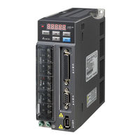
Delta ASD-B2-1021-B User Manual (345 pages)
Standard AC Servo Drive for General Purpose Applications
Brand:
Delta
| Category:
Servo Drives
| Size: 11.73 MB
Table of Contents
Table of Contents
6
Inspection
14
Nameplate Information
15
Product Model
15
Model Explanation
16
Servo Drive and Corresponding Servo Motor
18
Servo Drive Features
20
Control Modes of Servo Drive
21
Chapter 2 Installation
22
Notes
22
Ambient Conditions of Storage
22
Ambient Conditions of Installation
23
Installation Direction and Space
24
Troubleshooting for the Motor Operation and Status
26
Servo Motor Mounting Directions and Precautions
26
Precautions for Using Oil Seal Servo Motors
27
Precautions for Using Couplings
28
Oil and Water Prevention Measures for the Servo Motor
29
Measures to Suppress Temperature Increase of the Servo Motor
29
Specification of Circuit Breaker and Fuse
30
EMI Filter Selection
31
Selection of Regenerative Resistor
33
Chapter 3 Wiring
40
Connections
40
Connecting to Peripheral Devices
40
Servo Drive Connectors and Terminals
41
Wiring Method
43
Specification of Motor Power Cable
45
Specification of Encoder Connector
47
Selection of Wiring Rod
51
Basic Wiring
53
Included) and Models below
53
750 W Models
54
Kw ~ 3 Kw Models
55
I / O Signal (CN1) Connection
56
I/O Signal (CN1) Connector Terminal Layout
56
Signals Explanation of Connector CN1
58
Wiring Diagrams (CN1)
66
DI and DO Signal Specified by Users
73
CN2 Connector
74
Wiring of CN3 Connector
76
Analog Monitor Output Connector - CN5
77
Standard Connection Example
78
Position (PT) Control Mode
78
Speed Control Mode
79
Torque Control Mode
80
Chapter 4 Panel Display and Operation
82
Panel Description
82
Parameter Setting Procedure
83
Status Display
84
Save Setting Display
84
Decimal Point
84
Alarm Message
84
Positive and Negative Sign Setting
85
Monitor Display
85
General Function
88
Operation of Fault Code Display
88
JOG Mode
89
Force DO Output
90
Digital Input Diagnosis Operation
91
Digital Output Diagnosis Operation
91
Chapter 5 Trial Operation and Tuning
92
Inspection Without Load
92
Applying Power to the Servo Drive
94
JOG Trial Run Without Load
98
Trial Run Without Load (Speed Mode)
99
Tuning Procedure
101
Flowchart of Tuning Procedure
102
Inertia Estimation Flowchart (with Mechanism)
103
Flowchart of Auto Tuning
104
Flowchart of Semi-Auto Tuning
105
Limit of Inertia Ratio
106
Mechanical Resonance Suppression Method
108
Tuning Modes and Parameters
109
Tuning in Manual Mode
110
Chapter 6 Control Modes of Operation
112
Selection of Operation Mode
112
Position Mode
114
Position Command in PT Mode
114
Control Structure of Position Mode
117
Electronic Gear Ratio
119
Low-Pass Filter
121
Gain Adjustment of Position Loop
122
Speed Mode
125
Selection of Speed Mode
125
Control Structure of Speed Mode
126
Smoothing Speed Command
127
The Scaling of Analog Command
131
Timing Diagram in Speed Mode
132
Gain Adjustment of Speed Loop
132
Resonance Suppression
139
Torque Mode
147
Selection of Torque Command
147
Control Structure of Torque Mode
148
Smooth Torque Mode
149
The Scaling of Analog Command
149
Timing Diagram of Torque Mode
151
Dual Modes
152
Speed / Position Dual Mode
152
Speed / Torque Dual Mode
153
Torque / Position Dual Mode
153
Others
154
The Use of Speed Limit
154
The Use of Torque Limit
154
Analog Monitor
155
The Use of Brake
160
Chapter 7 Parameters
162
Parameter Definition
162
Lists of Parameters
163
Parameter Description
173
P0-XX Monitor Parameters
173
P1-XX Basic Parameters
182
P2-XX Extension Parameters
212
P3-XX Communication Parameters
241
P4-XX Diagnosis Parameters
246
Chapter 8 Communications
270
RS-232 Communication Hardware Interface
270
RS-232Communication Parameter Settings
272
MODBUS Communication Protocol
275
Write-In and Read-Out Communication Parameters
287
Chapter 9 Troubleshooting
288
Alarm of Servo Drive
288
Causes and Corrective Actions
291
Corrective Actions after the Alarm Occurs
302
Chapter 10 Specifications
307
Torque Features (T-N Curves)
315
Overload Features
317
Dimensions of Servo Drives
319
Dimensions of Servo Motors
323
Advertisement
Related Products
Delta ASD-B2-0121-B
Delta ASD-B2-0221-B
Delta ASD-B2-1521-B
Delta ASD-B2-2023-B
Delta ASD-B2-3023-B
Delta ASD-B2-0421-B
Delta ASD-B2-0721-B
Delta ASDA-A2 Series
Delta AS Series
Delta AS16AN01T-B
Delta Categories
Plumbing Product
Kitchen & Bath Fixtures
Bathroom Fixtures
Saw
Power Supply
More Delta Manuals
Login
Sign In
OR
Sign in with Facebook
Sign in with Google
Upload manual
Upload from disk
Upload from URL