Sign In
Upload
Manuals
Brands
Controlotron Manuals
Measuring Instruments
1010PVDN
Controlotron 1010PVDN Flowmeter Manuals
Manuals and User Guides for Controlotron 1010PVDN Flowmeter. We have
1
Controlotron 1010PVDN Flowmeter manual available for free PDF download: Field Manual
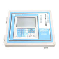
Controlotron 1010PVDN Field Manual (203 pages)
NEMA CLAMP-ON MULTI-FUNCTION FLOWMETER
Brand:
Controlotron
| Category:
Measuring Instruments
| Size: 5.82 MB
Table of Contents
Table of Contents
16
Getting Started
23
Introduction
23
Important Safety Considerations
23
Flowmeter Installation Steps
23
The Keypad Enable Switch
24
The 1010PVN Keypad
24
Keypad Function Chart
24
Introduction to the 1010PVN Menu Screens
24
Explanation of the Callouts
25
How to Use the Installation Menu
25
Accessing and Leaving the Menu
26
How to Enter Data
26
Selecting Items from an Option List
27
Multiple Select Option Lists
28
Entering Numeric Data
28
Entering Alphanumeric Strings
29
The Meter Type Menu
29
Dual Path
29
Creating a New Site Setup
30
The 1010PVN Installation Menu
33
The Channel/Path Setup Menu
34
The Channel/Path Setup Menu Structure
34
How to Recall a Site Setup
34
How to Enable and Disable a Sensing Path
35
How to Create/Name a Site Setup
36
How to Enable/Disable Site Security
36
How to Delete a Site Setup
37
How to Save/Rename a Site Setup
37
The Pipe Data Menu
38
The Pipe Data Menu Structure
40
How to Select a Pipe Class
41
How to Select a Pipe Size
41
How to Enter the Pipe OD (In. or MM)
42
How to Select a Pipe Material
42
How to Enter the Wall Thickness
42
Liner Material
43
Liner Thickness
43
Thermexp Coef
43
Mod of Elast PSI
44
The Application Data Menu
44
The Application Data Menu Structure
44
How to Select a Liquid Class
46
How to Edit the Estimated Vs (Liquid Sonic Velocity)
46
How to Edit the Viscosity (Cs) Setting
47
How to Edit the Density (SG) Setting
47
Activating the Liquid Table
47
Setting the Liquident™ Slope
48
Setting the Pressure Slope
49
The Reference Base Temperature
49
Setting the Liquident™ Index
50
Index Value
50
Viscosity
50
Visc Slope
50
How to Select a Pipe Temperature Range
51
Pipe Configuration
51
Pipe Configuration Menu Structure
52
Pipe Configuration Option List Definitions
52
The Pick/Install XDCR (Transducer) Menu
53
How to Select a Transducer Model
55
How to Select a Transducer Size
55
How to Select a XDCR Mount Mode
55
How to Use the Spacing Offset
55
The Number Index Menu Cell
56
Reviewing the Spacing Method
56
The Ltn Menu Cell
57
How to Use [Install Completed?]
57
Force Transmit Procedure
58
The Empty Pipe Set Menu
61
How to Use the Actual MTY Command
61
How to Use the Mtymatic Command
61
How to Use the Set Empty Command
62
Autozero
62
Actual Zero
62
Reversamatic
62
Zeromatic TM
63
Using Actual Zero
63
Using Reversamatic
63
Zeromatic (Optional Function)
64
The Operation Adjust Menu
66
Operation Adjust Menu Structure
66
Damping Control
67
Deadband Control
67
Memory/Fault Set
67
Memory Delay (Sec)
68
The Flow/Total Units Menu
68
Totalizer Controls
69
Flow/Total Units Menu Structure
70
Flow Volume Units
71
Flow Time Units
71
Flow Display Range
71
Flow Display Scale
72
Total Volume Units
72
Totalizer Scale
73
Total Resolution
73
Totalizer Mode
74
Batch/Sample Total
74
The Data Span/Set/Cal Menu
74
Data Span/Set/Cal Menu Structure
75
Span Data
77
Pgen
77
Max Flow
78
Min Flow
78
Max Liquident
78
Min Liquident
78
Max Vs M/S
78
Min Vs M/S
78
Max Viscosity Cs
79
Min Viscosity Cs
79
Max Temperature
79
Min Temperature
79
Set Alarm Levels
79
High Flow
79
Low Flow
79
Max Liquident
80
Min Liquident
80
High Viscosity Cs
80
Low Viscosity Cs
80
High Temperature
80
Low Temperature
80
Interface Vs M/S
80
Aeration
80
Makeup Latch
81
Calibrate Flowrate and Calibration Tables
81
Intrinsic
81
Kc Calibration
82
Kc Factor
82
Selecting the Kc Factor
82
Calibration Tables 1 through 3
83
The Stripchart Setup Menu
84
Select Data
85
Data Display
85
Time Base
85
Stripchart Clear
86
The Datalogger Setup Menu
86
Datalogger Setup Menu Structure
87
Datalogger Mode
88
Datalogger Data
88
Alarm Letter Codes and Descriptions
89
Log Time Interval
89
Datalogger Events
89
Display Datalogger
90
The I/O Data Control Menu
91
Analog Output Setup
93
1010PVN Analog Outputs
93
Analog out Setup Data Categories
93
Assigning Io Output Functions
94
Assigning Vo Output Functions
94
Assigning Pgen Output Functions
94
Relay Setup
95
Assigning Relay 1 and 2 Functions
95
Relay Option List
95
Analog Input Setup (Optional Function)
96
Setting up the Analog Current Input
97
The Diagnostics Data Menu
97
Main Diagnostics Data Screen
97
Diagnostics Data Menu Structure
98
Diagnostic Main Menu Description
99
Flow Data Menu
99
Flow Data Menu Items
99
Vs M/S
100
Hiflow and Loflow
100
Ancal
100
The Application Info Menu
101
Application Info Menu Items
102
The Liquid Data Menu
102
Liquid Data Menu Items
102
The Site Setup Data Menu
103
Site Setup Menu Items
103
Introduction to [HF] Menu Item
103
Using the [HF] Menu Item
104
Manual" Adjustment Procedure
105
Automatic" Adjustment Procedure
105
The Test Facilities Menu
107
Test Facilities Commands
107
Makeup
107
The Test Facilities Graph Screen
108
Entering the Diagnostic Graph Screen
109
Diagnostic Text Display
109
Time Base Control
109
Correlated Plot
109
Command Modes
110
Description of Graph Screen Text Display Parameters
112
Hot Key Summary
112
Troubleshooting Tips
113
Flow Computer Messages
113
Using the "F4" Reset Sequence
114
Troubleshooting with Transducer Test Blocks
116
Using the 1012Tb-1 and 2 Test Blocks
116
Using the 996PSP Pipe Simulator
118
If a Pipe Simulator/Test- Block Test Fails
119
Guide to a Smooth Installation
120
Checklist for 1010 Startup & Performance
120
Programming
120
Installation/Transducer Mount Guidelines
120
Start-Up
121
Diagnostic/Performance Verification
121
Optimization/Correction of Problems
121
Incorrect "Measured Vs
121
Low Valc
122
Detection Fault/Low Signal
122
High Vaer
122
Poor Signal
123
Official" Coupling Compound
123
Alternative" Coupling Compound
123
Ideal Vsig Display
123
Hardware Installation Guide
124
Preparing to Mount the Transducers
124
How to Identify 1011 Transducers and Mounting Hardware
124
Selecting a Location for Clamp-On Transducers
124
Clamp-On Transducer Mounting Modes
125
Preparing the Pipe
126
Reflect Mode with EZ Clamp and Spacer Bar Only
127
Direct Mode with EZ Clamp and Spacer Bar Only
128
Reflect Mode-Mounting Frames and Spacer Bar
132
Reflect Mode with Spacer Bar Only
133
Direct Mode-Mounting Frames, Spacer Bar and Spacing Guides
135
Using 1012T Mounting Tracks
139
Installing a 1012T Mounting Track in Reflect Mode
139
Installing a 1012T Mounting Track in Direct Mode
141
Mounting Temperature Sensors
143
Wiring Temperature Sensor to the Analog Input Module
144
1010PVN Supply and Return Connections
145
Notes on System 1010 Analog Input Modules
146
Single Channel Models
146
The Meter Facilities Menu and Graphic Display Screens
148
Preferred Units
148
The Table Setups Menu
149
Pipe Table
149
Pipe Table Menu Structure
149
Create/Edit Pipe
150
Delete Pipe
151
Transducer Type Menu
151
Transducer Type Menu Structure
152
The Datalogger Control Menu
153
Datalogger Control Menu Structure
153
Display Datalogger
153
Output Datalogger
154
Circular Memory
154
Est Log Time Left
155
Clear Datalogger
155
The Memory Control Menu
155
The Analog Output Trim Menu
156
Analog Output Trim Menu Structure
156
Current Output Trim (Io1 & Io2)
156
Voltage Output Trim (Vo1 & Vo2)
156
Pgen Output Trim (Pgen 1 & Pgen 2)
157
The RTD Calibrate Menu (Optional)
157
RTD Calibrate Menu Structure
158
Ice Bath RTD Calibration
158
The Clock Set Menu
159
Clock Set Menu Structure
159
Date
159
Time
159
Setup
160
Baud Rate
160
Parity
161
Data Bits
161
Line Feed
161
Network ID
162
RTS Key Time
162
Backlight
163
System Info
163
System Info Menu Structure
163
The 1010 Graphic Display Screens
163
System 1010 Application Notes
166
To Obtain Technical Assistance
166
Considerations for Critical Applications
166
Pipe Considerations for Clamp-On Transducers
167
Pipe Dimensions
167
Picking the Appropriate Transducer
167
Flow Velocity Range
167
Overview of System Performance
168
Accuracy
168
Repeatability
168
Data Stability
168
Data Scatter
168
Data Drift
169
Flow Conditions
169
Low Flow Rates
169
Flow Data Scatter and Damping
169
System 1010 Damping and Slewing Controls
169
Time Average
169
Smartslew
170
Notes on Liquid Conditions
170
Erroneous Liquid Parameter Specification
170
Liquid Compatibility
170
Aeration
170
Slurries
171
Two-Phase Liquids
171
Viscous Liquids
171
Temperature and Pressure Ratings
171
Overview of System 1010PVN Memory Resources
171
Reference Tables
172
System 1010 Reynolds Compensation Factor
174
DV Liquid Tables
174
Recommended Sonic Coupling Compounds
175
Terminology Chart
176
The Meter Type Menu
178
The Meter Facilities Menu
178
The Clamp-On Menu
179
Advertisement
Advertisement
Related Products
Controlotron 1010PVN
Controlotron Categories
Measuring Instruments
More Controlotron Manuals
Login
Sign In
OR
Sign in with Facebook
Sign in with Google
Upload manual
Upload from disk
Upload from URL