Sign In
Upload
Manuals
Brands
Carrier Manuals
Heat Pump
38MARBQ24AA3
Carrier 38MARBQ24AA3 Manuals
Manuals and User Guides for Carrier 38MARBQ24AA3. We have
1
Carrier 38MARBQ24AA3 manual available for free PDF download: Service Manual
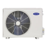
Carrier 38MARBQ24AA3 Service Manual (117 pages)
Outdoor Unit Single Zone Ductless System
Brand:
Carrier
| Category:
Heat Pump
| Size: 35.32 MB
Table of Contents
Table of Contents
1
Introduction
1
Unit Sizes
2
Model / Serial Number Nomenclatures
2
Specifications - Heat Pump
3
Dimensions and Weights
4
Clearances for Multiple Units
7
Clearances
7
Recommended Connection Method for Power and Communication Wiring
8
Electrical Data
8
Wiring
8
Connection Diagrams
9
Wiring Diagram Size 12K (115V)
10
Wiring Diagrams
10
Fan and Motor Specifications
14
Refrigeration Cycle Diagrams
15
Refrigerant Cycle Diagrams 9K (208/230V)
16
Refrigerant Cycle Diagram 12K (208/230V)
17
Refrigerant Cycle Diagram 18K (208/230V)
18
Long Line Applications
22
General Refrigerant Line Sizing
22
Refrigerant Lines
22
System Vacuum and Charge
23
Using Vacuum Pump
23
Deep Vacuum Method
23
System Evacuation and Charging
23
Main Protection
24
Outdoor Fan Running Rules
24
Inverter Module Protection
24
Electronic Functions
24
Evaporator Temperature Protection
25
Indoor Fan Running Rules
25
Compressor Temperature Protection
25
DEFROST Mode
27
Forced DEFROSTING Mode
27
Evaporator Coil Temperature Protection
28
DRYING Mode
28
FORCED OPERATION Function
28
Enquiry Information
29
Point Check Function
29
Electrolytic Capacitors
30
Discharge Position
30
Safety
30
Troubleshooting
30
Indoor Unit Diagnostic Guides
31
Outdoor Unit Error Display
32
Sizes 12 (115V)
32
Diagnosis and Solution
32
Indoor and Outdoor Unit Communication Error (EL01)
34
Zero Crossing Detection Error Diagnosis and Solution (EH02)
36
The Indoor Fan Speed Is Operating Outside of the Normal Range (EH03)
37
DC Fan Motor (Control Chip Is in the Fan Motor)
38
The Outdoor Fan Speed Is Operating Outside of Normal Range (EC07)
39
Outdoor DC Fan Motor (DC Motor that Controls the Chip on the PCB)
40
Refrigerant Leakage Detection (EL0C)
43
Indoor Pcb/Display Board Communication Error (EH06)
44
Current Overload Protection (PC08)
45
IPM Malfunction or IGBT Over-Strong Current Protection (PC00)
46
IPM Continuity Check
47
Compressor Check
48
Over Voltage or Low Voltage Protection (PC01)
49
Inverter Compressor Drive Error (PC04)
52
Low Pressure Protection (PC03)
53
Indoor Units Mode Conflict (Match with Multi Outdoor Unit)
54
Check Procedures
56
Temperature Sensor Check
56
Resistance Value
57
Way Valve Check
59
Measure the Voltage
59
Use a Digital Tester to Measure Resistance
59
EXV Check
60
Winding Colors
60
Main Parts Check
61
Temperature Sensor Checking
61
Pressure on Service Port
62
Cooling Chart
62
Heating Chart (R410A)
63
System Pressure
64
System Pressure Table-R410A
64
Outdoor Unit Sizes 9-12K (115V) Panel Plate
65
Disassembly Instructions
65
PCB Board 3
92
Four Way Valve (for Heat Pump Models)
110
Compressor
111
Safety Caution
113
Temperature Sensor Resistance Value Table for T1, T2, T3, T4
114
Temperature Sensor Resistance Value Table for T5
115
Advertisement
Advertisement
Related Products
Carrier 38MARBQ12AA1
Carrier 38MARBQ09AA3
Carrier 38MARBQ12AA3
Carrier 38MARBQ18AA3
Carrier 38MARBQ30AA3
Carrier 38MARBQ36AA3
Carrier 38MARB
Carrier bryant Multi-Zone 38MARBQ09 18AA3 Series
Carrier bryant Multi-Zone 38MARBQ24 36AA3 Series
Carrier bryant Multi-Zone 38MAQBR
Carrier Categories
Air Conditioner
Heat Pump
Furnace
Thermostat
Chiller
More Carrier Manuals
Login
Sign In
OR
Sign in with Facebook
Sign in with Google
Upload manual
Upload from disk
Upload from URL