Sign In
Upload
Manuals
Brands
CAREL Manuals
Controller
IR32 Series
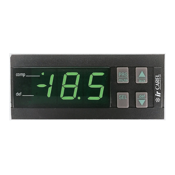
CAREL IR32 Series Temperature Controller Manuals
Manuals and User Guides for CAREL IR32 Series Temperature Controller. We have
1
CAREL IR32 Series Temperature Controller manual available for free PDF download: User Manual
CAREL IR32 Series User Manual (82 pages)
Universal infrared controllers
Brand:
CAREL
| Category:
Controller
| Size: 0.91 MB
Table of Contents
Italian
2
Table of Contents
2
Introduzione
4
Caratteristiche Principali
4
Descrizione del Frontale Degli Strumenti
5
Utilizzo Degli Strumenti Della Serie Infrared Universale
6
Installazione
7
Configurazione DI Fabbrica
8
Modi DI Funzionamento
9
Programmazione
14
Accesso da Tastiera
14
Modifica del Set-Point (St1)
14
Modifica del Secondo Set-Point (St2)
14
Parametri "C" Per Termocoppie, Sonde in Tensione E in Corrente
15
Come Modificare Il Modo (Parametro C0)
16
Accesso da Telecomando
16
Modifica Parametri da Telecomando
18
Stato Della Regolazione Durante la Modifica Dei Parametri
19
Validità Della Modifica Parametri
19
Reset del Controllo
19
Sistemi Avanzati DI Programmazione E Supervisione
19
Descrizione Dei Parametri
20
St1 Set-Point Principale
20
St2 Set-Point Secondario
20
C0 Modo DI Funzionamento
21
P1 Differenziale DI St1
21
P2 Differenziale DI St2
22
P3 Differenziale Zona Neutra
22
C4 Autorità
22
C5 P O P+I
23
C6 Ritardo Degli Inserimenti DI Uscite Differenti
24
C7 Tempo Minimo Tra Due Accensioni Successive
24
C8 Tempo Minimo DI Spegnimento
25
C9 Tempo Minimo DI Attivazione
25
C10 Ritardo Delle Uscite in Caso DI Allarme Sonda (Er0)
26
C11 Rotazioni
26
C12 Tempo DI Ciclo PWM
28
C13 Tipo DI Sonda
29
P14 Calibrazione
29
C15 Valore Minimo Per Ingressi in Corrente E Tensione
30
C16 Valore Massimo Per Ingressi in Corrente E Tensione
30
C17 Filtro Sonda
31
C18 Unità DI Misura Per Temperatura: "C" O "F
31
C19 Seconda Sonda NTC
32
Funzionamento Differenziale C19=1
32
Compensazione C19=2, 3 O 4
34
C21 Valore Minimo Ammesso da ST1
37
C22 Valore Massimo Ammesso da St1
37
C23 Valore Minimo Ammesso da ST2
37
C24 Valore Massimo Ammesso da St2
38
P25 SET Allarme DI "Bassa
38
P26 SET Allarme DI ALTA
38
P27 Differenziale ALLARME: Reset
39
P28 Ritardo Attivazione Allarme
41
C29 Gestione Ingresso Digitale 1
41
C29=3 Allarme Esterno Ritardato (Ritardo=P28)
42
C29=4 On/Off
42
C30 Gestione Ingresso Digitale 2
43
C31 Stato Uscite con Allarme da Ingresso Digitale
43
C32 Indirizzo Seriale
44
C33 Funzionamento "Speciale
44
C50 Abilitazione Tastiera E/O Telecomando
45
C51 Telecomando: Codice Abilitazione
45
Descrizione Funzionamento Speciale
46
Descrizione DIPENDENZA
46
Funzionamento TIMER
47
Descrizione INSERZIONE
47
Descrizione DIFFERENZIALE/LOGICA
49
Note Integrative al Funzionamento Speciale
50
Suggerimenti Per Scegliere Il Modo DI Partenza
53
Esempi DI Utilizzo del Funzionamento Speciale
54
Lista Completa Dei Parametri
61
Ricerca E Eliminazione Dei Guasti (Strumento E Telecomando)
63
Condizioni DI Allarme, Cause E Rimedi
64
Moduli Opzionali
65
Modulo Uscita Analogica
65
Modulo ON/OFF
67
Modulo Alimentatore/Convertitore
69
Caratteristiche Tecniche Dei Modelli Serie Infrared Universale
71
Caratteristiche Tecniche del Telecomando
72
Schemi DI Collegamento
73
Versioni IR32 NTC
73
Versioni IR32 Non NTC
74
Versioni IRDR NTC E Non NTC
76
Connessione Sonde
77
Glossario
78
Tabella Codici Dei Modelli Serie Infrared Universale
79
Dimensioni
81
English
4
Introduction to the IR Series
4
Main Features
4
C29, Digital Input no
4
Front Panel
5
C30, Digital Input no
5
Use of Universal Infrared Instruments
6
How to Install the Controller
7
Easy Set-Up: Factory-Set Configuration
8
Advanced Set-Up: Different Modes of Operation
9
Modifica Dei Parametri DI Tipo "P
14
Programming the IR Controller
14
Access Via Keypad
14
Set-Point Modification (St1)
14
Second Set-Point Modification (St2)
14
Modification of 'P' Parameters
14
Modifica Dei Parametri DI Tipo "C
15
Modification of 'C' Parameters
15
Programming the Controller Via Remote Control
16
How to Modify Parameters Via Remote Control
18
Confirming the Newly Set Values
19
Reset of the Control
19
Advanced Programming Tools and Supervisory Systems
19
Description of the Parameters
20
St1, Main Set-Point
20
St2, Second Set-Point
20
C0 Mode of Operating
21
P3, Dead Zone
22
C4, Authority
22
C5, P or P+I
23
C6, Time-Delay before Energizations of Different Outputs
24
C7, Minimum Time-Interval between Succ. Energizations
24
C8, Minimum Disenergization Time-Interval
25
C9, Minimum Energization Time-Interval
25
C10, Time-Delay before Sensor Alarm (Er0)
26
C11, Rotations
26
C12, PWM Cycle Time
28
C13, Type of Sensor
29
P14, Calibration
29
C15, Min. Value of Voltage and Current Inputs
30
C16, Max. Value of Voltage and Current Inputs
30
C17, Sensor Response
31
C18, Temperature Unit of Measure °C/°F
31
C19, Second NTC Sensor
32
C19=1, Differential
32
C19=2,3,4, Offse
34
C21, Lower St1 Threshold
37
C22, Higher St1 Threshold
37
C23, Lower St2 Threshold
37
C24, Higher St2 Threshold
38
P25, Low Temperature Set-Point
38
P26, High Temperature Set-Point
38
P27, Alarm Differential: Reset
39
P28, Time-Delay before Alarm Activation
41
C29=3 Delayed External Alarm with Manual Resert (P28)
42
C31, Output Status in the Event of Alarm Via Digital Input
43
C32, Serial Address
44
C33, Special Mode of Operation
44
C50, Operating Keypad And/Or Remote Control
45
C51, Remote Control: Access Code
45
Special Mode of Operation
46
Dependence
46
Timer
47
Further Information on the Special Mode of Operation
50
Hints for Choosing the Right Mode
53
Advanced Set-Up: List of the Parameters
61
Alarm Conditions, Causes and Remedies
64
Optional Modules
65
Analogue Output Module - Code CONV0/10A0
65
ON/OFF Module (Code CONV0N0FF0)
67
Technical Specifications of the Remote Control
72
Wiring Diagrams
73
IR32 with NTC Input
73
IR32 with Pt100, J/K Tc or V/I Input
74
IRDR Versions
76
Sensor Connection Diagrams
77
Glossary
78
Codes of the Universal Infrared Models
79
Dimensions
81
Advertisement
Advertisement
Related Products
Carel IR32S
Carel IR32M
Carel IR32P
Carel IR32Y
Carel IR32C
Carel ir33+wide
Carel IR33V7LR20
Carel IR33V9HR20
Carel IR33B9MR20
Carel IR33E9HB20
CAREL Categories
Controller
Humidifier
Control Unit
Touch terminals
Accessories
More CAREL Manuals
Login
Sign In
OR
Sign in with Facebook
Sign in with Google
Upload manual
Upload from disk
Upload from URL