Sign In
Upload
Manuals
Brands
Bonfiglioli Manuals
DC Drives
act 401
User Manuals: Bonfiglioli act 401 Inverter Drive
Manuals and User Guides for Bonfiglioli act 401 Inverter Drive. We have
2
Bonfiglioli act 401 Inverter Drive manuals available for free PDF download: Operating Instructions Manual, Quick Start Manual
Bonfiglioli act 401 Operating Instructions Manual (218 pages)
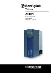
Vectron Active 201/401 Series 230V/400V 0.55 kW ... 132. kW frequency inverter
Brand:
Bonfiglioli
| Category:
DC Drives
| Size: 4.71 MB
Table of Contents
Installation Instructions
3
Table of Contents
4
Operating Instructions ACTIVE Operating Instructions ACTIVE 5
7
Operating Instructions ACTIVE Operating Instructions ACTIVE 7
9
1 General Safety Instructions and Information on Use
10
General Information
10
Purpose of the Frequency Inverters
11
Transport and Storage
11
Handling and Installation
11
Electrical Connection
12
Information on Use
12
Maintenance and Service
12
2 Scope of Supply
13
ACT 201 (up to 3.0 Kw) and ACT 401 (up to 4.0 Kw)
13
ACT 201 (4.0 up to 9.2 Kw) and ACT 401 (5.5 up to 15.0 Kw)
14
ACT 401 (18.5 up to 30.0 Kw)
15
ACT 401 (37.0 up to 65.0 Kw)
16
ACT 401 (75.0 up to 132.0 Kw)
17
3 Technical Data
18
General Technical Data
18
Technical Data of Control Electronics
19
ACT 201 (0.55 up to 3.0 Kw, 230 V)
20
ACT 201 (4.0 up to 9.2 Kw, 230 V)
21
ACT 401 (0.55 up to 4.0 Kw, 400 V)
22
ACT 401 (5.5 up to 15.0 Kw, 400 V)
23
ACT 401 (18.5 up to 30.0 Kw, 400 V)
24
ACT 401 (37.0 up to 65.0 Kw, 400 V)
25
ACT 401 (75.0 up to 132.0 Kw, 400 V)
26
Operation Diagrams
27
4 Mechanical Installation
28
ACT 201 (up to 3.0 Kw) and ACT 401 (up to 4.0 KW)
28
ACT 201 (4.0 up to 9.2 Kw) and ACT 401 (5.5 up to 15.0 Kw)
29
ACT 401 (18.5 up to 30.0 Kw)
30
ACT 401 (37.0 up to 65.0 Kw)
31
ACT 401 (75.0 up to 132.0 Kw)
32
5 Electrical Installation
33
EMC Information
34
Block Diagram
35
Optional Components
36
Connection of the Device
37
Dimensioning of the Conductor Cross Section
37
Typical Conductor Cross Sections
37
Mains Connection
38
Motor Connection
39
Motor Cable Length, Without Filter
39
Motor Cable Length, with Output Filter Du/Dt
39
Motor Cable Length, with Sine Filter
39
Group Drive
40
Speed Sensor Connection
40
Connection of a Brake Resistor
40
Connection of the Construction Sizes
41
ACT 201 (up to 3.0 Kw) and ACT 401 (up to 4.0 Kw)
41
ACT 201 (4.0 up to 9.2 Kw) and ACT 401 (5.5 up to 15.0 Kw)
43
ACT 401 (18.5 up to 30.0 Kw)
45
ACT 401 (37.0 up to 65.0 Kw)
47
ACT 401 (75.0 up to 132.0 Kw)
49
Control Terminals
51
Relay Output
52
Control Terminals - Terminal Diagram
53
Configuration 110 - Sensorless Control
53
Configuration 111 - Sensorless Control with Technology Controller
54
Configuration 410 - Sensorless Field-Oriented Control
54
Configuration 411 - Sensorless Field-Oriented Control with Technology Controller
55
Configuration 430 - Sensorless Field-Oriented Control, Speed or Torque Controlled
55
Configuration 210 - Field-Oriented Control, Speed Controlled
56
Configuration 211 - Field-Oriented Control, with Technology Controller
56
Configuration 230 - Field-Oriented Control, Speed and Torque Controlled
57
6 Control Unit KP500
58
Menu Structure
59
Main Menu
59
Actual Value Menu (VAL)
60
Parameter Menu (PARA)
61
Copy Menu (CPY)
62
Reading the Stored Information
62
Menu Structure
63
Selecting the Source
63
Selecting the Destination
64
Copy Operation
64
Error Messages
65
Read Data from the KP 500 Control Unit
66
Activating
66
Transfer Data
67
Reset to Normal Mode
68
Control Menu (CTRL)
68
Controlling the Motor Via the Control Unit
69
7 Commissioning of the Frequency Inverter
72
Switching on Mains Voltage
72
Setup Using the Control Unit
72
Configuration
73
Data Set
74
Motor Type
74
Machine Data
75
Plausibility Check
76
Parameter Identification
77
Application Data
79
Acceleration and Deceleration
79
Set Points at Multi-Functional Input
80
Selection of an Actual Value for Display
80
Check Direction of Rotation
81
Speed Sensor
82
Speed Sensor 1
82
Speed Sensor 2
83
Set-Up Via the Communication Interface
84
8 Inverter Data
86
Serial Number
86
Optional Modules
86
Inverter Software Version
86
Set Password
86
Control Level
87
User Name
87
Configuration
87
Language
90
Programming
90
9 Machine Data
91
Rated Motor Parameters
91
Further Motor Parameters
92
Stator Resistance
92
Leakage Coefficient
92
Magnetizing Current
93
Rated Slip Correction Factor
93
Internal Values
94
Speed Sensor 1
94
Operation Mode Speed Sensor 1
94
Division Marks, Speed Sensor 1
95
10 System Data
96
Actual Value System
96
Volume Flow and Pressure
96
11 Operational Behavior
97
Starting Behavior
97
Starting Behavior of Sensorless Control System
97
Starting Current
99
Frequency Limit
99
Flux Formation
99
Stopping Behavior
100
Switch-Off Threshold
102
Holding Time
102
Direct Current Brake
102
Auto Start
103
Search Run
104
Positioning
105
Reference Positioning
106
Error and Warning Behavior
111
Overload Ixt
111
Temperature
111
Controller Status
112
IDC Compensation Limit
112
Frequency Switch-Off Limit
112
Motor Temperature
113
Phase Failure
113
Automatic Error Acknowledgment
114
13 Reference Values
115
Frequency Limits
115
Slip Frequency
115
Percentage Value Limits
115
Frequency Reference Channel
116
Block Diagram
117
Reference Percentage Channel
119
Block Diagram
119
Fixed Reference Values
121
Fixed Frequencies
121
JOG-Frequency
121
Fixed Percentages
122
Frequency Ramps
122
Percentage Value Ramps
125
Block Frequencies
125
Motor Potentiometer
126
Motorpoti (MP)
127
Motorpoti (KP)
127
Controlling the Motor Via the Control Unit
128
Repetition Frequency Input
129
14 Control Inputs and Outputs
130
Multi-Function Input MFI1
130
Analog Input MFI1A
130
Characteristic
130
Scaling
132
Tolerance Band and Hysteresis
132
Filter Time Constant
133
Error and Warning Behavior
134
Multi-Function Output MFO1
134
Analog Output MFO1A
135
Output Characteristic
135
Frequency Output MFO1F
136
Scaling
136
Digital Outputs
137
Setting Frequency
138
Reference Value Reached
138
06/07 Operating Instructions ACTIVE
138
Flux Formation Ended
139
Open Brake
139
Current Limitation
139
External Fan
139
Warning Mask
140
Digital Inputs
142
Start Command
145
3-Wire-Control
145
Error Acknowledgment
146
Timer
146
Thermo-Contact
146
N-/M-Control Change-Over
146
Data Set Change-Over
147
Fixed Value Change-Over
148
Motor Potentiometer
149
Function Modules
149
Timer
149
Time Constant
150
Comparator
152
Logic Modules
153
15 F - Characteristic
158
Dynamic Voltage Pre-Control
159
16 Control Functions
160
Intelligent Current Limits
160
Voltage Controller
161
Technology Controller
165
Functions of Sensorless Control
173
Slip Compensation
173
Current Limit Value Controller
173
Functions of Field-Orientated Control
174
Current Controller
174
Torque Controller
176
Limit Value Sources
176
Speed Controller
177
Limitation of Speed Controller
179
Limit Value Sources
180
Acceleration Pre-Control
180
Field Controller
181
Limitation of Field Controller
182
Modulation Controller
182
Limitation of Modulation Controller
183
17 Special Functions
184
Pulse Width Modulation
184
Fan
185
Bus Controller
185
Brake Chopper and Brake Resistance
187
Dimensioning of Brake Resistor
188
Motor Circuit Breaker
189
V-Belt Monitoring
190
Motor Chopper
191
Temperature Adjustment
192
Encoder Monitoring
193
Actual Values
194
Actual Values of the Frequency Inverter
194
Actual Values of the Machine
195
Actual Value Memory
196
Actual Values of the System
197
Error Protocol
199
Error List Description
199
Error Messages
199
Error Environment
201
Operational and Error Diagnosis
203
Status Display
203
Status of Digital Signals
203
Controller Status
204
Warning Status
205
Parameter List
206
Advertisement
BONFIGLIOLI act 401 Quick Start Manual (96 pages)
Brand:
BONFIGLIOLI
| Category:
DC Drives
| Size: 6.97 MB
Table of Contents
Italiano
3
Table of Contents
3
Installazione Meccanica
4
Installazione Elettrica
7
Avvertenze EMI
7
ACT 201 (a 3,0 Kw) E ACT 401 (a 4,0 Kw)
8
ACT 201 (da 4,0 Kw a 9,2 Kw) E ACT 401 (da 5,5 Kw a 15,0 Kw)
8
ACT 401 (da 18,5 Kw a 30,0 Kw)
9
ACT 401 (da 37,0 Kw a 65,0 Kw)
9
ACT 401 (da 75,0 Kw a 132,0 Kw)
10
Messa in Servizio con Unità DI Comando KP500
11
Morsetti DI Comando
11
Funzioni Dei Tasti
12
Messa in Servizio Guidata
12
Impostazioni Dei Parametri
14
Grandezze DI Funzionamento
17
Messaggi Dell'unità DI Comando
17
Messaggi DI Avviso Ed Errore Durante Il Funzionamento
18
Messaggi DI Avviso Ed Errore Durante la Messa in Servizio
19
English
21
Mechanical Installation
22
Electrical Installation
25
EMC Information
25
ACT 201 (4.0 Kw to 9.2 Kw) and ACT 401 (5.5 Kw to 15.0 Kw)
26
ACT 201 (up to 3.0 Kw) and ACT 401 (up to 4.0 Kw)
26
ACT 401 (18.5 Kw to 30.0 Kw)
27
ACT 401 (37.0 Kw to 65.0 Kw)
27
ACT 401 (75.0 Kw to 132.0 Kw)
28
Commissioning Via the Control Unit KP500
29
Control Terminals
29
Functions of Keys
30
Guided Commissioning
30
Parameter Settings
32
Actual Values
35
Control Unit Messages
35
Warning and Error Messages During Operation
36
Warning and Error Messages During Guided Commissioning
37
Deutsch
39
Mechanische Installation
40
Elektrische Installation
43
EMV - Hinweise
43
ACT 201 (4,0 Kw bis 9,2 Kw) und ACT 401 (5,5 Kw bis 15,0 Kw)
44
ACT 201 (bis 3,0 Kw) und ACT 401 (bis 4,0 Kw)
44
ACT 401 (18,5 Kw bis 30,0 Kw)
45
ACT 401 (37,0 Kw bis 65,0 Kw)
45
ACT 401 (75,0 Kw bis 132,0 Kw)
46
Inbetriebnahme mit der Bedieneinheit KP500
47
Steuerklemmen
47
Geführte Inbetriebnahme
48
Tastenfunktionen
48
Parametereinstellungen
51
Istwerte
54
Meldungen der Bedieneinheit
54
Warn- und Fehlermeldungen während des Betriebs
55
Warn- und Fehlermeldungen während der Inbetriebnahme
56
Français
59
Installation Mécanique
60
Avertissements EMI
63
Installation Électrique
63
ACT 201 (de 4,0 Kw À 9,2 Kw) Et ACT 401 (de 5,5 Kw À 15,0 Kw)
64
ACT 201 (À 3,0 Kw) Et ACT 401 (À 4,0 Kw)
64
ACT 401 (de 18,5 Kw À 30,0 Kw)
65
ACT 401 (de 37,0 Kw À 65,0 Kw)
65
ACT 401 (de 75,0 Kw À 132,0 Kw)
66
Bornes de Commande
67
Mise en Service Avec Unité de Commande KP500
67
Fonction des Touches
68
Mise en Service Guidée
68
Configuration des Paramètres
70
Grandeurs de Fonctionnement
73
Messages de L'unité de Commande
73
Messages D'avertissement Et D'erreur Pendant Le Fonctionnement
74
Messages D'avertissement Et D'erreur Pendant la Mise en Service
75
Español
77
Instalación Mecánica
78
Advertencias EMI
81
Instalación Eléctrica
81
ACT 201 (a 3,0 Kw) y ACT 401 (a 4,0 Kw)
82
ACT 201 (de 4,0 Kw a 9,2 Kw) y ACT 401 (de 5,5 Kw a 15,0 Kw)
82
ACT 401 (de 18,5 a 30,0 Kw)
83
ACT 401 (de 37,0 Kw a 65,0 Kw)
83
ACT 401 (de 75,0 Kw a 132,0 Kw)
84
Bornes de Control
85
Puesta en Servicio con Consola de Programación KP500
85
Funciones de las Teclas
86
Puesta en Servicio Guiada
86
Ajustes de Los Parámetros
88
Mensajes de la Consola de Programación
91
Valores de Funcionamiento
91
Mensajes de Aviso y Error Durante el Funcionamiento
92
Mensajes de Aviso y Error Durante la Puesta en Servicio
93
Advertisement
Related Products
BONFIGLIOLI Active ACT 401-05
BONFIGLIOLI Active ACT 401-07
BONFIGLIOLI Active ACT 401-09
BONFIGLIOLI Active ACT 401-11
BONFIGLIOLI Active ACT 401-12
BONFIGLIOLI Active ACT 401-13
BONFIGLIOLI Active ACT 401-21
BONFIGLIOLI Active ACT 401-22
BONFIGLIOLI Active ACT 401-23
BONFIGLIOLI Active ACT 401-25
Bonfiglioli Categories
DC Drives
Engine
Inverter
Industrial Equipment
Servo Drives
More Bonfiglioli Manuals
Login
Sign In
OR
Sign in with Facebook
Sign in with Google
Upload manual
Upload from disk
Upload from URL