Sign In
Upload
Manuals
Brands
Biotek Manuals
Card Reader
Synergy H1
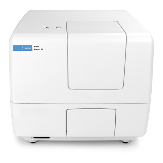
Biotek Synergy H1 Multi-Mode Reader Manuals
Manuals and User Guides for Biotek Synergy H1 Multi-Mode Reader. We have
3
Biotek Synergy H1 Multi-Mode Reader manuals available for free PDF download: Operator's Manual, Instructions For Use Manual
Biotek Synergy H1 Operator's Manual (190 pages)
Hybrid Multi-Mode Microplate Reader
Brand:
Biotek
| Category:
Laboratory Equipment
| Size: 6.51 MB
Table of Contents
Notices
4
Trademarks
4
Restrictions and Liabilities
4
Table of Contents
5
Contact Information
12
Global Service and Support
12
Customer Service and Sales
12
Service/Technical Assistance Center (TAC)
12
European Coordination Center/Authorized European Representative
12
Revision History
13
Document Conventions
16
Intended Use Statement
16
Quality Control
17
Warranty and Product Registration
17
Repackaging and Shipping
17
Warnings
18
Hazards
18
Precautions
19
CE Mark
21
Directive 2014/30/EU: Electromagnetic Compatibility
21
Emissions-Class a XIX
21
Immunity
21
Directive 2014/35/EU Low Voltage (Safety)
21
Directive 2012/19/EU: Waste Electrical and Electronic Equipment
22
Directive 98/79/EC: in Vitro Diagnostics (if Labeled for this Use)
22
Electromagnetic Interference and Susceptibility
22
Usa Fcc Class a
22
Canadian Department of Communications Class a XX
22
User Safety
23
Safety Symbols
24
Introduction
27
Product Description
28
Absorbance Liquid Test
28
Package Contents & Accessories
29
Optional Accessories
30
Materials for Conducting Liquid Tests
31
Product Support & Service
32
Technical Assistance Center (TAC)
32
Applications Support
32
Installation
33
Product Registration
34
Important Information
34
1: Unpack and Inspect the Synergy H1
35
2: Select an Appropriate Location
35
3: Remove the Shipping Hardware
36
4: Install the Power Supply
37
5: Install the Gas Controller
37
6: Unpack and Inspect the Dispense Module
38
7: Install the Dispense Module
39
8: Connect the Host Computer
42
9: Install Gen5 Software
43
10: Turn on the Reader
43
11: Establish Communication
43
12: Verify/Set Dispenser Calibration Values
44
13: Run a System Test
45
14: Test the Injection System
46
Operational/Performance Qualification
47
Repackaging and Shipping Instructions
48
Prepare the Dispense Module for Shipment
51
Getting Started
55
Modular Design
56
External Components
57
Internal Components
57
Filter Cube
58
Injection System
59
Dispense Module
59
Priming the Injection System
60
Gen5 Software
61
Define the Filter Cube in Gen5 and on the Reader
61
Protocols and Experiments
62
Dispense Module Control
63
Prime
63
Purge
63
Plate Shaking Options
64
Recommendations for Optimum Performance
65
General
65
Luminescence Measurements
66
Monochromator-Based Fluorescence Systems
66
Models with Injectors
66
Incubation and Partial Plates
66
Kinetic Assays Using the Continuous Shake Feature
67
Filters and Mirrors
69
Filter Cube Overview
70
Removing a Filter Cube
72
Installing a Filter Cube
72
Configuring the System for Luminescence Measurements
73
About the Gen5 Optics Library
73
Adding a Filter Cube to the Gen5 Optics Library
73
Handling Filters and Mirrors
75
Change a Filter or Mirror
75
Clean the Filters and Mirrors
78
Filters and Mirrors Available from Biotek
78
Preventive Maintenance
79
Overview
80
Daily Cleaning for the Dispense Module
80
Recommended Maintenance Schedule
81
Warnings and Precautions
82
Clean Exposed Surfaces
83
Inspect/Clean Excitation and Emission Filters
84
Inspect/Clean Mirrors
85
Materials
85
Procedure
86
Flush/Purge Fluid Path
87
Run a Dispense Protocol (Optional)
88
Empty/Clean the Tip Priming Trough
89
Clean the Priming Plate
89
Clean the Dispense Tubes and Injectors
89
Required Materials
89
Remove the Dispense Tubes and Injector Tip Holder
90
Clean the Dispense Tubes and Injectors
90
As-Needed Maintenance
91
Decontamination
92
Required Materials
92
Procedure for Models Without the Dispense Module
93
Procedure for Models with the Dispense Module
94
Routine Procedure
94
Clean Exposed Surfaces
94
Decontaminate the Fluid Lines
95
Rinse the Fluid Lines
95
Clean the Tubing and Injectors
96
Decontaminate the Tip Priming Trough and Priming Plate
96
Alternate Procedure
96
Dispense Module, Syringe Replacement
97
Syringe Maintenance Position
97
Replace the Syringe
98
Instrument Qualification Process
99
Instrument System Test
100
Plate Shaker Test
100
Absorbance Testing
101
Biotek Absorbance Test Plates
101
Test Methods
101
Sample Test Report
102
Troubleshooting
102
Peak Absorbance Test
102
Alignment Test
103
Accuracy Test
103
Repeatability Test
103
Absorbance Liquid Tests
103
Test Methods
103
Gen5 Protocol Parameters
104
Results Analysis
106
Absorbance Liquid Test 1
106
Absorbance Liquid Test 3
107
Troubleshooting
108
Luminescence Testing
109
Test Method
109
Gen5 Protocol Parameters
109
Results Analysis
111
Pass/Fail Criteria
112
Troubleshooting
112
Fluorescence Testing
113
Biotek Fluorescence Test Plate
113
Results Analysis
113
Fluorescence Liquid Tests
114
Test Methods
114
Gen5 Protocol Parameters
114
Results Analysis
124
Corners Test
124
Sensitivity Test
124
Linearity Test
125
Fluorescence Polarization (FP) Test
125
Time-Resolved Fluorescence (TRF) Test
126
Troubleshooting
127
Injection System Testing
128
Test Method
128
Gen5 Parameters
128
Results Analysis
131
Instrument Qualification Procedures
133
Overview
134
IQ/OQ/PQ Description
135
Recommended Qualification Schedule
136
System Test
137
Setup
137
Test Procedure
137
Absorbance Plate Tests
138
Requirements
138
Setup
138
Test Procedure
139
Absorbance Liquid Tests
140
Absorbance Liquid Test 1
140
Materials
140
Solution a
140
Solution B
141
Test Procedure
141
Absorbance Liquid Test 2
142
Materials
142
Test Procedure
142
Absorbance Liquid Test 3
143
Materials
143
Buffer Solution
143
Test Procedure
144
Luminescence Test
145
Requirements
145
Test Procedure
145
Fluorescence Plate Tests
146
Requirements
146
Test Procedure
146
Fluorescence Liquid Tests
147
Materials
147
All Tests
147
Corners/Sensitivity/Linearity (FI) Tests
149
Fluorescence Polarization (FP) Test
149
Time-Resolved Fluorescence (TRF) Test
150
Test Solutions
150
Corners/Sensitivity/Linearity (FI) Tests
150
Fluorescence Polarization (FP) Test
151
Time-Resolved Fluorescence (TRF) Test
151
Test Procedure
152
Pipette Maps
153
Corners, Sensitivity, and Linearity (FI) Tests
153
Fluorescence Polarization (FP) Test
154
Time-Resolved Fluorescence (TRF) Test
155
Alternate/Supplemental Tests Using Methylumbelliferone (MUB)
156
Materials
156
Test Solutions
157
Test Procedure
158
Pipette Map
159
Injection System Tests
160
Materials
160
Alternate Test Solutions
161
Test Procedure for Models with Absorbance Capability
161
Test Procedure for Models Without Absorbance Capability
163
Specifications
167
Absorbance Specifications
167
General Specifications
168
Microplates
168
Hardware and Environmental
168
Monochromator-Based Fluorescence
168
Optics
169
Performance
169
Accuracy
169
Linearity
169
Repeatability
170
Fluorescence Specifications
170
Performance
170
Dispense/Read Specifications
170
Filter-Based Fluorescence
171
Fluorescence Intensity
171
Time-Resolved Fluorescence
171
Fluorescence Polarization
171
Luminescence Specifications
171
Error Codes
173
Overview
174
Instrument Dimensions for Robotic Interface
179
Sample Reports
183
Advertisement
Biotek Synergy H1 Operator's Manual (184 pages)
Hybrid Multi-Mode Microplate Reader
Brand:
Biotek
| Category:
Laboratory Equipment
| Size: 2.75 MB
Table of Contents
Table of Contents
5
Global Service and Support
7
Revision History
9
Document Conventions
11
Intended Use Statement
11
Quality Control
12
Repackaging and Shipping
12
Warnings
12
Warranty and Product Registration
12
Hazards
13
Precautions
14
CE Mark
15
Electromagnetic Interference and Susceptibility
16
User Safety
17
Safety Symbols
18
Chapter 1 Introduction
21
Introduction
21
Product Description
22
Package Contents & Accessories
23
Optional Accessories
24
Product Support & Service
26
Technical Assistance Center (TAC)
26
Applications Support
26
Chapter 2 I Nstallation
27
I Nstallation
27
Important Information
28
Product Registration
28
1: Unpack and Inspect the Reader
29
2: Unpack and Inspect the Dispense Module
30
3: Unpack and Inspect the Gas Controller
31
4: Select an Appropriate Location
31
5: Remove the Shipping Hardware
32
6: Install the Power Supply
33
7: Connect the Gas Controller
33
8: Install the Dispense Module
33
9: Connect the Host Computer
37
10: Install Gen5 on the Host Computer
38
11: Turn on the Reader
38
12: Establish Communication
38
13: Run a System Test
39
14: Test the Injector System
40
Operational/Performance Qualification
42
Repackaging and Shipping Instructions
42
Preparing the Dispense Module for Shipment
46
Chapter 3 Getting Started
49
Getting Started
49
Modular Design
50
External Components
51
Internal Components
51
Filter Cube
52
Injector System
53
Gen5 Software
56
Define the Filter Cube
56
Protocols and Experiments
57
Dispense Module Control
58
Recommendations for Optimum Performance
59
General
59
Kinetic Assays Using the Continuous Shake Feature
60
Luminescence Measurements
60
Monochromator-Based Fluorescence Systems
61
Models with Injectors
61
Chapter 4 Filters and Mirrors
63
Filter Cube Overview
64
Removing a Filter Cube
66
Installing a Filter Cube
66
Adding a Filter Cube to the Optics Library
67
Filters and Mirrors
64
Filters and Mirrors
68
Change the Filters and Mirrors
69
Clean the Filters and Mirrors
72
Filters Available from Biotek
72
Mirrors Available from Biotek
72
Chapter 5 Preventive Maintenance
73
Preventive Maintenance
74
Daily Cleaning for the Dispense Module
74
Warnings and Precautions
75
Schedule
75
Clean Exposed Surfaces
76
Inspect/Clean Excitation and Emission Filters
77
Inspect/Clean Mirrors
78
Materials
78
Procedure
78
Flush/Purge the Fluid Path
80
Run a Dispense Protocol (Optional)
81
Empty/Clean the Tip Priming Trough
82
Clean the Priming Plate
82
Clean the Dispense Tubes and Injectors
83
Remove the Dispense Tubes and Injector Holders
83
Required Materials
83
Clean the Dispense Tubes and Injectors
84
Chapter 6 As-Needed Maintenance
85
As-Needed Maintenance
85
Decontamination
86
Decontamination
87
Required Materials
87
Procedure for Models Without the Dispense Module
87
Procedure for Models with the Dispense Module
88
Clean Exposed Surfaces
88
Routine Procedure
88
Decontaminate the Fluid Lines
89
Clean the Tubing and Injectors
90
Decontaminate the Tip Priming Trough and Priming Plate
90
Rinse the Fluid Lines
90
Alternate Procedure
91
Dispense Module: Syringe Replacement
92
Syringe Maintenance Position
92
Replace the Syringe
92
Chapter 7 I Nstrument Qualification
95
I Nstrument Qualification
95
Iq/Oq/Pq
97
Overview
97
Recommended Qualification Schedule
98
Absorbance Plate Test
99
System Test
99
Absorbance Plate Test
105
Define Absorbance Test Plate Parameters
106
Run the Absorbance Plate Test
107
Sample Absorbance Plate Test Report
108
Results and Troubleshooting Tips
110
Absorbance Liquid Tests
111
Absorbance Liquid Test 1
111
Absorbance Liquid Test 2
114
Absorbance Liquid Test 3 (Optional)
116
Fluorescence Liquid Tests
119
Required Materials
120
Test Solutions
123
Procedure
125
Pipette Maps
126
Results Analysis
129
Troubleshooting
132
Gen5 Protocol Reading Parameters
133
Fluorescence Test Procedure (Methylumbelliferone)
135
Luminescence Test
142
Harta Plate Test
142
Glowell Test
144
Gen5 Protocol Reading Parameters
145
Troubleshooting
148
Dispense Module Tests
149
Required Materials
150
Alternate Test Solutions
150
Appendix A Specifications
163
Specifications
163
Appendix A
164
General Specifications
164
This Appendix Contains Biotek's Published Specifications for the
164
Dispense/Read Specifications
165
Absorbance Specifications
166
Dispense/Read Specifications
167
Fluorescence Specifications (Mono-Based)
167
Fluorescence Specifications (Filter-Based)
168
Luminescence Specifications
169
Error Codes
171
Overview
172
Error Codes
173
Instrument Dimensions for Robotic Interface
177
Biotek Synergy H1 Instructions For Use Manual (99 pages)
Hybrid Multi-Mode Microplate Reader For In Vitro Diagnostic Use
Brand:
Biotek
| Category:
Card Reader
| Size: 2.22 MB
Table of Contents
Contact Information
3
Instructions for Use Requirements
4
Intended Use Statement
4
Quality Control
4
Warnings
5
Hazards
5
Precautions
6
CE Mark
8
Directive 2006/95/EC Low Voltage (Safety)
8
Immunity
8
Electromagnetic Interference and Susceptibility
9
Canadian Department of Communications Class a
9
User Safety
10
Safety Symbols
11
Installation
13
Package Contents
14
Unpack and Inspect the Reader
15
Unpack and Inspect the Dispense Module
15
Unpack and Inspect the Gas Controller
16
Select an Appropriate Location
16
Remove the Shipping Hardware
17
Install the Power Supply
17
Connect the Gas Controller
18
Install the Dispense Module
18
Connect the Host Computer
21
Install Gen5 on the Host Computer
22
Turn on the Reader
22
Establish Communication
22
Run a System Test
23
Test the Injector System
24
Repackaging and Shipping Instructions
25
Getting Started
27
Overview
28
External Components
29
Internal Components
29
Filter Cube
29
Excitation and Emission Filters
30
Configuring the System for Luminescence Measurements
30
Mirrors
30
Injector System
31
Dispense Module
31
Priming the Injector System
32
Gen5 Software
33
Define the Filter Cube
33
Protocols and Experiments
34
Dispense Module Control
35
Prime
35
Purge
36
Maintenance
37
Preventive Maintenance
38
Daily Cleaning for the Dispense Module
38
Schedule
39
Warnings and Precautions
39
Clean Exposed Surfaces
40
Inspect/Clean Excitation and Emission Filters
41
Inspect/Clean Mirrors
41
Materials
42
Procedure
42
Flush/Purge the Fluid Path
43
Empty/Clean the Tip Prime Trough
44
To Flush the Fluid Path
44
To Purge the Fluid from the System
44
Clean the Priming Plate
45
Clean the Dispense Tubes and Injectors
45
Required Materials
45
Remove the Dispense Tubes and Injector Holders
46
Decontamination
47
To Clean the Injectors
47
Procedure for Models Without the Dispense Module
48
Procedure for Models with the Dispense Module
49
Routine Procedure
49
Decontaminate the Fluid Lines
50
Rinse the Fluid Lines
51
Clean the Tubing and Injectors
51
Decontaminate the Tip Prime Trough and Priming Plate
51
Instrument Testing
53
System Test
54
Absorbance Plate Test
54
Setup
54
Results and Troubleshooting Tips
56
Peak Absorbance
56
If the Test Fails
57
Alignment
57
Accuracy
57
Repeatability
57
Absorbance Liquid Test
58
Fluorescence Liquid Tests
60
Filter Set Setup
62
Corners/Sensitivity/Linearity Tests
62
Fluorescence Polarization (FP) Test
63
Time-Resolved Fluorescence (TRF) Test
63
Test Solutions
63
Pipette Maps
66
Corners Test
67
Sensitivity and Linearity Tests
67
Results Analysis
70
Sensitivity Test
70
Monochromator-Based Fluorescence System
70
Linearity Test
71
Troubleshooting
73
Gen5 Protocol Reading Parameters
74
H1_Fi_T_Sf.prt
74
H1_Fp.prt
75
H1_Trf.prt
75
H1_M_Fi_T_Sf.prt
76
H1_M_Fi_B_Sf.prt
76
Luminescence Test
77
Harta Plate Test
78
Glowell Test
79
F-Lumtest_Harta.prt
80
Dispense Module Tests
84
Test Solution Formulas
85
Using Biotek’s Blue and Yellow Concentrate Dye Solutions
85
Using FD&C Blue and Yellow Dye Powder
85
Procedure for Models with Absorbance Capabilities
86
Failures
87
Gen5 Test Protocols for Models with Absorbance Capabilities
88
Add Data Reduction Steps
90
Specifications
91
General Specifications
92
Dispense/Read Specifications
94
Absorbance Specifications
95
Fluorescence Specifications (Mono-Based)
97
Monochromator-Based Fluorescence
97
Sodium Fluorescein in Phosphate Buffered Saline (PBS)
97
Methylumbelliferone (MUB) in Carbonate-Bicarbonate Buffer (CBB)
97
Fluorescence Specifications (Filter-Based)
98
Optical Probes
98
Sensitivity
98
Luminescence Specifications
98
Advertisement
Advertisement
Related Products
Biotek Synergy HTX
BioTek Synergy HT
Biotek Synergy LX
BioTek Cytation 5
Biotek Categories
Laboratory Equipment
Water Filtration Systems
Measuring Instruments
Card Reader
Washer
More Biotek Manuals
Login
Sign In
OR
Sign in with Facebook
Sign in with Google
Upload manual
Upload from disk
Upload from URL