Sign In
Upload
Manuals
Brands
Beckhoff Manuals
Control Unit
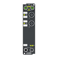
EP3174-0002
User Manuals: Beckhoff EP3174-0002 EtherCAT Box Input
Manuals and User Guides for Beckhoff EP3174-0002 EtherCAT Box Input. We have
1
Beckhoff EP3174-0002 EtherCAT Box Input manual available for free PDF download: Documentation
Beckhoff EP3174-0002 Documentation (149 pages)
EtherCAT Box modules with analog inputs
Brand:
Beckhoff
| Category:
Control Unit
| Size: 3.69 MB
Table of Contents
Table of Contents
3
1 Foreword
7
Notes on the Documentation
7
Safety Instructions
8
Documentation Issue Status
9
2 Product Overview
11
Ethercat Box - Introduction
11
Fig. 1 Ethercat Box Modules Within an Ethercat Network
11
Fig. 2 Ethercat Box with M8 Connections for Sensors/Actuators
12
Fig. 3 Ethercat Box with M12 Connections for Sensors/Actuators
12
Module Overview
13
EP3162 - Introduction
14
Fig. 4 EP3162-0002
14
EP3162 - Technical Data
15
EP3162 - Scope of Supply
17
EP3162 - Process Image
17
EP3182 - Introduction
18
Fig. 5 EP3182-1002
18
EP3182 - Technical Data
19
EP3182 - Scope of Supply
21
EP3182 - Process Image
22
Ep31X4
24
EP3174-0002 - Introduction
24
Fig. 6 EP3174-0002
24
EP3174-0092 - Introduction
25
Fig. 7 EP3174-0092
25
EP3184-0002 - Introduction
26
Fig. 8 EP3184-0002
26
EP3184-1002 - Introduction
27
Fig. 9 EP3184-1002
27
Ep31X4 - Technical Data
28
Ep31X4 - Scope of Supply
30
Ep31X4 - Process Image
30
EP3174-0092 - Process Image (with Twinsafe SC Modules)
31
3 Mounting and Cabling
32
Mounting
32
Dimensions
32
Fig. 10 Dimensions
32
Fixing
33
Tightening Torques for Plug Connectors
33
Ethercat
34
Connectors
34
Fig. 11 Ethercat Connector
34
Fig. 12 M8 Socket
34
Status Leds
35
Cables
35
Fig. 13 Ethercat Status Leds
35
Supply Voltages
36
Connectors
36
Fig. 14 Connectors for Supply Voltages
36
Fig. 15 M8 Connector
36
Status Leds
37
Conductor Losses
37
Fig. 16 Status Leds for the Power Supply
37
UL Requirements
38
Fig. 17 UL Label
38
ATEX Notes
39
ATEX - Special Conditions
39
BG2000 - Ethercat Box Protection Enclosures
40
Fig. 18 BG2000 - Putting the Cables
40
ATEX Documentation
41
Fig. 19 BG2000 - Fixing the Cables
41
Fig. 20 BG2000 - Mounting the Protection Enclosure
41
EP3162-0002 - Electrical Isolation of the Channels
42
Fig. 21 Block Diagram: Electrical Isolation
42
EP3162-0002 - Signal Connection and Status Leds
43
Analog Voltage Inputs M12, One Single-Ended Input Per Socket
43
Fig. 22: M12 Analog Voltage Input, Channel 1
43
Fig. 23: M12 Analog Voltage Input, Channel 2
43
M12 Analog Current Inputs, One Single-Ended Input Per Socket
44
Fig. 24: M12 Analog Current Inputs, Channel 1
44
Fig. 25: M12 Analog Current Inputs, Channel 2
44
Status Leds at the M12 Connections
45
Fig. 26 Status Leds at the M12 Connections
45
EP3174-00X2 - Signal Connection and Status Leds
46
M12 Analog Voltage Inputs, One Differential Input Per Socket
46
M12 Analog Current Inputs, One Differential Input Per Socket
46
Fig. 27 M12 Analog Voltage Inputs, One Differential Input Per Socket
46
Fig. 28 M12 Analog Current Inputs, One Differential Input Per Socket
46
Status Leds at the M12 Connections
47
Fig. 29 Status Leds at the M12 Connections
47
EP3182-1002 - Signal Connection and Status Leds
48
Analog Voltage Inputs, M12 Digital Output, One Single-Ended Input and One Digital Output Per Socket
48
Analog Current Inputs, M12 Digital Output, One Single-Ended Input and One Digital Output Per Socket
48
Fig. 30 M12 Analog Voltage Inputs
48
Fig. 31 M12 Current Inputs
48
Status Leds at the M12 Connections
49
EP3184-0002 - Signal Connection and Status Leds
49
Analog Voltage Inputs M12, One Single-Ended Input Per Socket
49
Fig. 32 Status Leds at the M12 Connections
49
Fig. 33 Analog Voltage Inputs M12, One Single-Ended Input Per Socket
49
M12 Analog Current Inputs, One Single-Ended Input Per Socket
50
Status Leds at the M12 Connections
50
Fig. 34 M12 Analog Current Inputs, One Single-Ended Input Per Socket
50
Fig. 35 Status Leds at the M12 Connections
50
EP3184-1002 - Signal Connection and Status Leds
51
M12 Analog Voltage Inputs, Two Single-Ended Inputs Per Socket
51
M12 Analog Current Inputs, Two Single-Ended Inputs Per Socket
51
Fig. 36 M12 Analog Voltage Inputs, Two Single-Ended Inputs Per Socket
51
Fig. 37 M12 Analog Current Inputs, Two Single-Ended Inputs Per Socket
51
Status Leds at the M12 Connections
52
Fig. 38 Status Leds at the M12 Connections
52
4 Configuration
53
Inserting into the Ethercat Network
53
Fig. 39 Scanning in the Configuration (I/O Devices -> Right-Click -> Scan Devices
53
Fig. 40 Appending a New I/O Device (I/O Devices -> Right-Click -> Append Device
54
Fig. 41 Selecting the Device Ethercat
54
Fig. 42 Appending a New Box (Device -> Right-Click -> Append Box
54
Fig. 43 Selecting a Box (E.g. EP2816-0008)
55
Fig. 44 Appended Box in the Twincat Tree
55
Configuration Via Twincat
56
Fig. 45 Branch of the Ethercat Box to be Configured
56
Fig. 46 General Tab
56
Fig. 47 Ethercat Tab
57
Fig. 48 Process Data Tab
58
Fig. 49 Startup Tab
60
Fig. 50 Coe - Online Tab
61
Fig. 51 Advanced Settings
62
Fig. 52 Online Tab
62
Ethercat State Machine
64
Fig. 53 Ethercat State Machine
64
Coe Interface
66
Fig. 54 Coe-Online Tab
67
Fig. 55 Startup List in the Twincat System Manager
68
Fig. 56 Offline List
69
Fig. 57 Online List
69
Notices on Analog Specifications
71
Fig. 58 Measuring Range
71
Fig. 59 Single-Ended/Differential Typification
72
Fig. 60 2/3/4-Wire Connection as Single-Ended or Differential Connection Technology
75
Ep31Xx - Settings and Operating Modes
76
Settings
76
Fig. 61 Ep31X4-0002: Selection of the Signal Type
76
Fig. 62 Ep31X2: Selection of the Signal Type
76
Operation Modes
81
Fig. 63 Typical Attenuation Curve of Notch Filter at 50 Hz
82
Data Stream
83
Fig. 64 Diagram Showing the Data Stream in the Ep31Xx
83
Measuring Ranges
84
Fig. 65 Data Flow with Correction Calculation for +/- 20 Ma
84
Fig. 66 Data Flow with Correction Calculation for 0
84
Fig. 67 Data Flow with Correction Calculation for 4
84
Calibration
85
Fig. 68 Data Flow with Correction Calculation for +/- 10 V
85
Fig. 69 Data Flow with Correction Calculation for 0
85
Calculation of Process Data
86
Twinsafe SC
86
Twinsafe SC - Operating Principle
86
Twinsafe SC - Configuration
86
Fig. 70 Adding the Twinsafe SC Process Data under the Component, E.g. EL5021-0090
87
Fig. 71 Twinsafe SC Component Process Data, Example EL5021-0090
87
Fig. 72 Adding a Twinsafe SC Connection
87
Fig. 73 Creating a Link to Twinsafe SC Terminal
88
Fig. 74 Selecting a Free CRC
88
Fig. 75 Selecting the Process Data Size and the Process Data
89
Fig. 76 Selection of the Process Data
89
Fig. 77 Coe Objects 0X8010:01 and 0X8010:02
89
EP3174-0092 - Twinsafe SC Process Data
90
Fig. 78 Entering the Safety Address and the CRC
90
EP3162-0002 - Object Overview
91
EP3182-1002 - Object Overview
94
Ep31X4-X002 - Object Overview
97
EP3174-0092 - Object Overview
103
Ep31X2 - Object Description and Parameterization
109
Ep31X4 - Object Description and Parameterization
123
Objects Twinsafe Single Channel (EP3174-0092)
139
Restoring the Delivery State
141
Fig. 79 Selecting the Restore Default Parameters PDO
141
Fig. 80 Entering a Restore Value in the Set Value Dialog
141
Decommissioning
142
5 Appendix
143
General Operating Conditions
143
Ethercat Box- / Ethercat P Box - Accessories
144
General Note on the Introduction of the Beckhoff Identification Code (BIC)
145
Support and Service
147
Table of Figures
148
Advertisement
Advertisement
Related Products
Beckhoff EP3174-0092
Beckhoff EP3204
Beckhoff EP3314
Beckhoff EP31 Series
Beckhoff EP3162
Beckhoff EP31 4 Series
Beckhoff EP3182
Beckhoff EP3184-0002
Beckhoff EP3184-1002
Beckhoff EP7211 Series
Beckhoff Categories
Touch terminals
Industrial PC
Control Unit
Touch Panel
Industrial Equipment
More Beckhoff Manuals
Login
Sign In
OR
Sign in with Facebook
Sign in with Google
Upload manual
Upload from disk
Upload from URL