
Related Manuals for Beckhoff EP31 Series


Summary of Contents for Beckhoff EP31 Series
- Page 1 Documentation EP31xx EtherCAT Box modules with analog inputs Version: Date: 2019-12-18...
-
Page 3: Table Of Contents
Table of contents Table of contents 1 Foreword .............................. 7 Notes on the documentation...................... 7 Safety instructions .......................... 8 Documentation issue status ...................... 9 2 Product overview............................. 11 EtherCAT Box - Introduction...................... 11 Module overview.......................... 13 EP3162 ............................ 14 2.3.1 EP3162 - Introduction ...................... 14 2.3.2 EP3162 - Technical data .................... 15 2.3.3 EP3162 - Scope of supply .................... - Page 4 Table of contents EP3162-0002 - Electrical isolation of the channels ................. 42 EP3162-0002 – Signal connection and Status LEDs .............. 43 3.7.1 Analog voltage inputs M12, one single-ended input per socket ........ 43 3.7.2 M12 analog current inputs, one single-ended input per socket ........ 44 3.7.3 Status LEDs at the M12 connections................
- Page 5 4.20 Restoring the delivery state ...................... 141 4.21 Decommissioning .......................... 142 5 Appendix .............................. 143 General operating conditions...................... 143 EtherCAT Box- / EtherCAT P Box - Accessories ................ 144 General note on the introduction of the Beckhoff Identification Code (BIC) ........ 145 Support and Service ........................ 147 EP31xx Version: 2.4...
- Page 6 Table of contents Version: 2.4 EP31xx...
-
Page 7: Foreword
EP1590927, EP1789857, EP1456722, EP2137893, DE102015105702 with corresponding applications or registrations in various other countries. ® EtherCAT is registered trademark and patented technology, licensed by Beckhoff Automation GmbH, Germany. Copyright © Beckhoff Automation GmbH & Co. KG, Germany. The reproduction, distribution and utilization of this document as well as the communication of its contents to others without express authorization are prohibited. -
Page 8: Safety Instructions
All the components are supplied in particular hardware and software configurations appropriate for the application. Modifications to hardware or software configurations other than those described in the documentation are not permitted, and nullify the liability of Beckhoff Automation GmbH & Co. KG. Personnel qualification This description is only intended for trained specialists in control, automation and drive engineering who are familiar with the applicable national standards. -
Page 9: Documentation Issue Status
Foreword Documentation issue status Version Modifications • EP3184-x002 - Introduction: graphics corrected • Structural update 2.3.0 • Nut torques for connectors updated • EP3174-0092 added • Chapter Mounting updated • Chapter Operation modes updated • Structural update 2.2.0 • EP3162-0002 - M12 analog voltage inputs updated •... - Page 10 HH - hardware version 01 - hardware version 01 Beckhoff Identification Code (BIC) The Beckhoff Identification Code contains additional information about the delivery state of the module: General note on the introduction of the Beckhoff Identification Code (BIC) [} 145]. Version: 2.4...
-
Page 11: Product Overview
Product overview Product overview EtherCAT Box - Introduction The EtherCAT system has been extended with EtherCAT Box modules with protection class IP 67. Through the integrated EtherCAT interface the modules can be connected directly to an EtherCAT network without an additional Coupler Box. The high-performance of EtherCAT is thus maintained into each module. The extremely low dimensions of only 126 x 30 x 26.5 mm (h x w x d) are identical to those of the Fieldbus Box extension modules. -
Page 12: Fig. 2 Ethercat Box With M8 Connections For Sensors/Actuators
EtherCAT, which is available for download from our website (www.beckhoff.com) under Downloads. EtherCAT XML Device Description You will find XML files (XML Device Description Files) for Beckhoff EtherCAT modules on our web- site (www.beckhoff.com) under Downloads, in the Configuration Files area. -
Page 13: Module Overview
Product overview Module overview Analog input modules, 24 V Module Number of Number of Signal Comment analog digital connection inputs outputs EP3162-0002 [} 14] 2 2 x M12 Single-ended inputs EP3174-0002 [} 24] 4 4 x M12 Differential inputs EP3174-0092 [} 25] 4 4 x M12 Differential inputs, TwinSAFE Single Channel EP3182-1002 [} 18] 2 2 x M12... -
Page 14: Ep3162 - Introduction
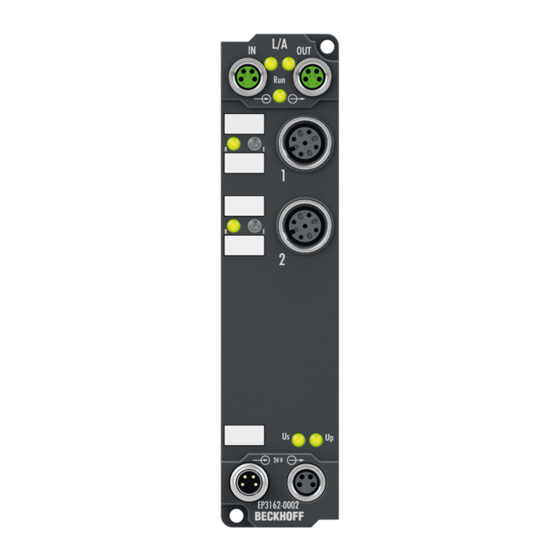
Product overview EP3162 2.3.1 EP3162 - Introduction Fig. 4: EP3162-0002 2-channel analog input ± 10 V or 0/4...20 mA, electrically isolated, single-ended, 16-bit The EP3162 EtherCAT Box has two analog inputs that can be individually parameterized to process signals either in the range from -10 V to +10 V or from 0/4 mA to 20 mA. The voltage or input current is digitized with a resolution of 16 bits, and is transmitted (electrically isolated) to the higher-level automation device. -
Page 15: Ep3162 - Technical Data
Product overview 2.3.2 EP3162 - Technical data Technical data EP3162-0002 Fieldbus Fieldbus EtherCAT Connection 2 x M8 socket, green Electrical isolation 500 V (fieldbus / IO) Distributed Clocks Supply voltages Connection Feed: 1 x M8 plug, 4-pin, black Downstream connection: 1 x M8 socket, 4-pin, black Control voltage U Nominal voltage 24 V... - Page 16 Product overview Technical data EP3162-0002 Environmental conditions Ambient temperature -25 .. +60 °C during operation -25 .. +55 °C according to cURus Ambient temperature -40 .. +85 °C during storage Vibration / shock resistance conforms to EN 60068-2-6 / EN 60068-2-27 EMC immunity / emission conforms to EN 61000-6-2 / EN 61000-6-4 Protection class IP65, IP66, IP67 conforms to EN 60529...
-
Page 17: Ep3162 - Scope Of Supply
Product overview 2.3.3 EP3162 - Scope of supply Make sure that the following components are included in the scope of delivery: • 1x EtherCAT Box EP3162-0002 • 1x protective cap for supply voltage input, M8, transparent (pre-assembled) • 1x protective cap for supply voltage output, M8, black (pre-assembled) •... -
Page 18: Ep3182 - Introduction
Product overview EP3182 2.4.1 EP3182 - Introduction Fig. 5: EP3182-1002 2-channel analog input ±10 V or 0/4...20 mA, parameterizable, single-ended, 16-bit, 2 digital control outputs 24 V , short-circuit proof Analog inputs (single-ended) The EP3182-1002 EtherCAT Box has two analog inputs which can be individually parameterized, so that they process signals either in the -10 V to +10 V range or the 0/4 mA…20 mA range. -
Page 19: Ep3182 - Technical Data
Product overview 2.4.2 EP3182 - Technical data Technical data EP3182-1002 Fieldbus Fieldbus EtherCAT Connection 2 x M8 socket, green Electrical isolation 500 V (fieldbus / IO) Supply voltages Connection Feed: 1 x M8 plug, 4-pin, black Downstream connection: 1 x M8 socket, 4-pin, black Control voltage U Nominal voltage 24 V... - Page 20 Product overview Technical data EP3182-1002 Digital outputs Number Connection M12 sockets of the analog inputs Nominal voltage 24 V from peripheral voltage U Output current I 2 mA per output, short-circuit proof Internal resistance approx. 2350 Ω (high level) Impedance of connected inputs min.
-
Page 21: Ep3182 - Scope Of Supply
Product overview 2.4.3 EP3182 - Scope of supply Make sure that the following components are included in the scope of delivery: • 1x EtherCAT Box EP3182-1002 • 1x protective cap for supply voltage input, M8, transparent (pre-assembled) • 1x protective cap for supply voltage output, M8, black (pre-assembled) •... -
Page 22: Ep3182 - Process Image
Product overview 2.4.4 EP3182 - Process image Analog inputs Table 1: AI Standard Channel 1 You will find the data of the 1 analog channel under AI Standard Channel 1. AI Standard Channel 2 The data of the second analog channel have the same structure as those of the first channel. Version: 2.4 EP31xx... - Page 23 Product overview Digital outputs Table 2: DO Outputs The digital outputs of the module can be found under DO Outputs. EP31xx Version: 2.4...
-
Page 24: Ep31X4
Product overview EP31x4 2.5.1 EP3174-0002 - Introduction Fig. 6: EP3174-0002 4-channel analog input ±10 V or 0/4...20 mA, parameterizable, differential input, 16-bit The EP3174-0002 EtherCAT Box has four analog inputs which can be individually parameterized, so that they process signals either in the -10 V to +10 V range or the 0/4 mA…20 mA range. The voltage or input current is digitized with a resolution of 16 bits, and is transmitted (electrically isolated) to the higher-level automation device. -
Page 25: Ep3174-0092 - Introduction
Product overview 2.5.2 EP3174-0092 - Introduction Fig. 7: EP3174-0092 4-channel analog input ±10 V or 0/4...20 mA, differential input, 16-bit, TwinSAFE Single Channel In addition to the full range of functions of the EP3174-0002, the EP3174-0092 supports the TwinSAFE SC technology (TwinSAFE Single Channel). This enables the use of standard signals for safety tasks in any networks of fieldbuses. -
Page 26: Ep3184-0002 - Introduction
Product overview 2.5.3 EP3184-0002 - Introduction Channel 1 Channel 2 Channel 3 Channel 4 Fig. 8: EP3184-0002 4-channel analog input ±10 V or 0/4...20 mA, parameterizable, single-ended, 16-bit The EP3184-0002 EtherCAT Box has four analog inputs which can be individually parameterized, so that they process signals either in the -10 V to +10 V range or the 0/4 mA…20 mA range. -
Page 27: Ep3184-1002 - Introduction
Product overview 2.5.4 EP3184-1002 - Introduction Channel 1 Channel 2 Channel 3 Channel 4 Fig. 9: EP3184-1002 4-channel analog input ±10 V or 0/4...20 mA, parameterizable, single-ended, 16-bit The EP3184-1002 EtherCAT Box has four analog inputs which can be individually parameterized, so that they process signals either in the -10 V to +10 V range or the 0/4 mA…20 mA range. -
Page 28: Ep31X4 - Technical Data
Product overview 2.5.5 EP31x4 - Technical data Technical data EP3174-0002 EP3174-0092 EP3184-0002 EP3184-1002 MTBF > 600,000 h Fieldbus Fieldbus EtherCAT Connection 2 x M8 socket, green Electrical isolation 500 V (fieldbus / IO) Distributed Clocks Supply voltages Connection Feed: 1 x M8 plug, 4-pin, black Downstream connection: 1 x M8 socket, 4-pin, black Control voltage U Nominal voltage... - Page 29 Product overview Technical data EP3174-0002 EP3174-0092 EP3184-0002 EP3184-1002 Environmental conditions Ambient temperature during operation -25 .. +60 °C -25 .. +55 °C conforms to cURus [} 38] 0 .. +55 °C conforms to ATEX [} 39] Ambient temperature during storage -40 .. +85 °C Vibration / shock resistance conforms to EN 60068-2-6 / EN 60068-2-27 EMC immunity / emission conforms to EN 61000-6-2 / EN 61000-6-4...
-
Page 30: Ep31X4 - Scope Of Supply
Product overview 2.5.6 EP31x4 - Scope of supply Make sure that the following components are included in the scope of delivery: • 1x EtherCAT Box EP3174-0002 / EP3174-0092 / EP3184-0002 / EP3184-1002 • 1x protective cap for supply voltage input, M8, transparent (pre-assembled) •... -
Page 31: Ep3174-0092 - Process Image (With Twinsafe Sc Modules)
Product overview 2.5.8 EP3174-0092 – Process image (with TwinSAFE SC modules) In the following illustration the process data are shown after inserting the TwinSAFE SC module as described in the chapter TwinSAFE SC configuration [} 86]. Under Module 1 (EP3174-0092) you will find •... -
Page 32: Mounting And Cabling
Mounting and cabling Mounting and cabling Mounting 3.1.1 Dimensions 26.5 13.5 Ø 3.5 Fig. 10: Dimensions All dimensions are given in millimeters. Housing features Housing material PA6 (polyamide) Sealing compound polyurethane Mounting two fastening holes Ø 3.5 mm for M3 Metal parts brass, nickel-plated Contacts CuZn, gold-plated Power feed through... -
Page 33: Fixing
Mount the module with two M3 screws on the fastening holes in the corners of the module. The fastening holes have no thread. 3.1.3 Tightening torques for plug connectors Screw connectors tight with a torque wrench. (e.g. ZB8801 from Beckhoff) Connector diameter Tightening torque 0.4 Nm 0.6 Nm... -
Page 34: Ethercat
Mounting and cabling EtherCAT 3.2.1 Connectors EtherCAT Box Modules have two green M8 sockets for the incoming and downstream EtherCAT connections. Fig. 11: EtherCAT connector Connection Fig. 12: M8 socket EtherCAT Core colors connector Signal Contact ZB9010, ZB9020, ZB9030, ZB9032, ZB9031 and old versions of TIA-568B ZK1090-6292, ZB9030, ZB9032, ZK1090-3xxx-... -
Page 35: Status Leds
(CAT5) according to EN 50173 or ISO/IEC 11801 should be used. EtherCAT uses four wires for signal transmission. Thanks to automatic line detection ("Auto MDI-X"), both symmetrical (1:1) or cross-over cables can be used between Beckhoff EtherCAT. Detailed recommendations for the cabling of EtherCAT devices EP31xx... -
Page 36: Supply Voltages
Plug Socket Feed-in Forwarding Fig. 15: M8 connector Contact Function Description Core color Control voltage Brown Peripheral voltage White GND to U Blue GND to U Black The core colors apply to cables of the type: Beckhoff ZK2020-xxxx-xxxx Version: 2.4 EP31xx... -
Page 37: Status Leds
Mounting and cabling 3.3.2 Status LEDs Fig. 16: Status LEDs for the power supply Display Meaning (control voltage) Supply voltage, U , is not present green illuminated Supply voltage, U , is present (peripheral voltage) Supply voltage, U , is not present green illuminated Supply voltage, U , is present... -
Page 38: Ul Requirements
Mounting and cabling UL Requirements The installation of the EtherCAT Box Modules certified by UL has to meet the following requirements. Supply voltage CAUTION CAUTION! This UL requirements are valid for all supply voltages of all marked EtherCAT Box Modules! For the compliance of the UL requirements the EtherCAT Box Modules should only be supplied •... -
Page 39: Atex Notes
Mounting and cabling ATEX notes 3.5.1 ATEX - Special conditions WARNING Observe the special conditions for the intended use of EtherCAT Box modules in poten- tially explosive areas – directive 94/9/EU. • The certified components are to be installed with a BG2000-0000 or BG2000-0010 protection enclosure [} 40] that guarantees a protection against mechanical hazards! •... -
Page 40: Bg2000 - Ethercat Box Protection Enclosures
Mounting and cabling 3.5.2 BG2000 - EtherCAT Box protection enclosures WARNING Risk of electric shock and damage of device! Bring the EtherCAT system into a safe, powered down state before starting installation, disassembly or wiring of the modules! ATEX WARNING Mount a protection enclosure! To fulfill the special conditions according to ATEX [} 39], a BG2000-0000 or BG2000-0010 protection enclo- sure has to be mounted over the EtherCAT Box. -
Page 41: Atex Documentation
Notes about operation of EtherCAT Box Modules (EPxxxx-xxxx) in potentially explo- sive areas (ATEX) Pay also attention to the continuative documentationNotes about operation of EtherCAT Box Mod- ules (EPxxxx-xxxx) in potentially explosive areas (ATEX) that is available in the download area of the Beckhoff homepage http:\\www.beckhoff.com! EP31xx Version: 2.4... -
Page 42: Ep3162-0002 - Electrical Isolation Of The Channels
Mounting and cabling EP3162-0002 - Electrical isolation of the channels The block diagram shown below illustrates the principle of the electrical isolation of the two channels. The 24 V with which the channels are supplied come from an electrically isolated DC/DC and are thus U instead of U Fig. 21: Block diagram: electrical isolation... -
Page 43: Ep3162-0002 - Signal Connection And Status Leds
Mounting and cabling EP3162-0002 – Signal connection and Status LEDs 3.7.1 Analog voltage inputs M12, one single-ended input per socket Analog input, -10 V to +10 V or 0 V to +10 V Fig. 22: M12 analog voltage input, channel 1 Fig. 23: M12 analog voltage input, channel 2 Refer to the chapter EP3162-0002 - Electrical isolation of the channels [} 42] for additional information. -
Page 44: M12 Analog Current Inputs, One Single-Ended Input Per Socket
Mounting and cabling 3.7.2 M12 analog current inputs, one single-ended input per socket Analog input, 0 mA to 20 mA, 4 to 20 mA or -20 mA to 20 mA Fig. 24: M12 analog current inputs, channel 1 Fig. 25: M12 analog current inputs, channel 2 Refer to the chapter EP3162-0002 - Electrical isolation of the channels [} 42] for additional information. Version: 2.4 EP31xx... -
Page 45: Status Leds At The M12 Connections
Mounting and cabling 3.7.3 Status LEDs at the M12 connections Fig. 26: Status LEDs at the M12 connections Connection Display Meaning M12 socket no. 0-1 R No data transfer to the A/D converter green Data transfer to A/D converter left Function OK Error: Broken wire or measured value outside the measuring right range... -
Page 46: Ep3174-00X2 - Signal Connection And Status Leds
Mounting and cabling EP3174-00x2 - Signal connection and Status LEDs 3.8.1 M12 analog voltage inputs, one differential input per socket Analog inputs, -10 V to +10 V differential Fig. 27: M12 analog voltage inputs, one differential input per socket GND connections If several sensors are connected to a box whose GND connections are not electrically isolated, GND must be connected to GNDp. -
Page 47: Status Leds At The M12 Connections
Mounting and cabling 3.8.3 Status LEDs at the M12 connections Fig. 29: Status LEDs at the M12 connections Connection Display Meaning M12 socket no. 1-4 R No data transfer to the A/D converter green Data transfer to A/D converter left Function OK Error: Broken wire or measured value outside the measuring right range... -
Page 48: Ep3182-1002 - Signal Connection And Status Leds
Mounting and cabling EP3182-1002 – Signal connection and Status LEDs 3.9.1 Analog voltage inputs, M12 digital output, one single-ended input and one digital output per socket Analog input, -10 to +10 V, digital output Fig. 30: M12 analog voltage inputs 3.9.2 Analog current inputs, M12 digital output, one single-ended input and one digital output per socket Analog input, 0 to 20 mA, 4 to 20 mA, digital output Fig. 31: M12 current inputs... -
Page 49: Status Leds At The M12 Connections
Mounting and cabling 3.9.3 Status LEDs at the M12 connections Fig. 32: Status LEDs at the M12 connections Connection Display Meaning M12 socket no. 1-2 R Analog input: No data transfer to the A/D converter green Analog input: Data transfer to A/D converter left Error at the analog input: Broken wire or measured value outside the measuring range... -
Page 50: M12 Analog Current Inputs, One Single-Ended Input Per Socket
Mounting and cabling 3.10.2 M12 analog current inputs, one single-ended input per socket Analog input, 0 to 20 mA, or 4 to 20 mA Fig. 34: M12 analog current inputs, one single-ended input per socket GND connections If several sensors are connected to a box whose GND connections are not electrically isolated, GND must be connected to GNDp. -
Page 51: Ep3184-1002 - Signal Connection And Status Leds
Mounting and cabling 3.11 EP3184-1002 – Signal connection and Status LEDs 3.11.1 M12 analog voltage inputs, two single-ended inputs per socket Analog inputs, -10 V to +10 V Fig. 36: M12 analog voltage inputs, two single-ended inputs per socket GND connections If several sensors are connected to a box whose GND connections are not electrically isolated, GND must be connected to GNDp. -
Page 52: Status Leds At The M12 Connections
Mounting and cabling 3.11.3 Status LEDs at the M12 connections Fig. 38: Status LEDs at the M12 connections Connection Display Meaning M12 socket no. 1, No data transfer to the A/D converter green Data transfer to A/D converter left Sockets 2 and 4 Function OK are not used. -
Page 53: Configuration
Beckhoff website (http://www.beckhoff.de/english/download/elconfg.htm? id=1983920606140) and installed according to the installation instructions. At the Beckhoff TwinCAT System Manager the configuration tree can be build in two different ways: • by scanning [} 53] for existing hardware (called "online") and •... -
Page 54: Fig. 40 Appending A New I/O Device (I/O Devices -> Right-Click -> Append Device
Configuration Fig. 40: Appending a new I/O device (I/O Devices -> right-click -> Append Device...) Fig. 41: Selecting the device EtherCAT • Append a new box. Fig. 42: Appending a new box (Device -> right-click -> Append Box...) • In the dialog that appears select the desired box (e.g. EP2816-0008), and confirm with OK. Version: 2.4 EP31xx... -
Page 55: Fig. 43 Selecting A Box (E.g. Ep2816-0008)
Configuration Fig. 43: Selecting a Box (e.g. EP2816-0008) Fig. 44: Appended Box in the TwinCAT tree EP31xx Version: 2.4... -
Page 56: Configuration Via Twincat
Configuration Configuration via TwinCAT In the left-hand window of the TwinCAT System Manager, click on the branch of the EtherCAT Box you wish to configure (EP2816-0008 in this example). Fig. 45: Branch of the EtherCAT box to be configured In the right-hand window of the TwinCAT System manager, various tabs are now available for configuring the EtherCAT Box. -
Page 57: Fig. 47 Ethercat Tab
Configuration EtherCAT tab Fig. 47: EtherCAT tab Type EtherCAT device type Product/Revision Product and revision number of the EtherCAT device Auto Inc Addr. Auto increment address of the EtherCAT device. The auto increment address can be used for addressing each EtherCAT device in the communication ring through its physical position. -
Page 58: Fig. 48 Process Data Tab
Configuration Fig. 48: Process Data tab Sync Manager Lists the configuration of the Sync Manager (SM). If the EtherCAT device has a mailbox, SM0 is used for the mailbox output (MbxOut) and SM1 for the mailbox input (MbxIn). SM2 is used for the output process data (outputs) and SM3 (inputs) for the input process data. If an input is selected, the corresponding PDO assignment is displayed in the PDO Assignment list below. - Page 59 Configuration Activation of PDO assignment • the EtherCAT slave has to run through the PS status transition cycle (from pre-operational to safe-operational) once (see Online tab [} 62]), • and the System Manager has to reload the EtherCAT slaves ( button) PDO list List of all PDOs supported by this EtherCAT device.
-
Page 60: Fig. 49 Startup Tab
Configuration Fig. 49: Startup tab Column Description Transition Transition to which the request is sent. This can either be • the transition from pre-operational to safe-operational (PS), or • the transition from safe-operational to operational (SO). If the transition is enclosed in "<>" (e.g. <PS>), the mailbox request is fixed and cannot be modified or deleted by the user. -
Page 61: Fig. 50 Coe - Online Tab
Configuration Fig. 50: CoE - Online tab Object list display Column Description Index Index and subindex of the object Name Name of the object Flags The object can be read, and data can be written to the object (read/write) The object can be read, but no data can be written to the object (read only) An additional P identifies the object as a process data object. -
Page 62: Fig. 51 Advanced Settings
Configuration Fig. 51: Advanced settings Online If this option button is selected, the list of the objects included in the object - via SDO information directory of the slave is uploaded from the slave via SDO information. The list below can be used to specify which object types are to be uploaded. Offline If this option button is selected, the list of the objects included in the object - via EDS file... - Page 63 Configuration State Machine Init This button attempts to set the EtherCAT device to the Init state. Pre-Op This button attempts to set the EtherCAT device to the pre-operational state. This button attempts to set the EtherCAT device to the operational state. Bootstrap This button attempts to set the EtherCAT device to the Bootstrap state.
-
Page 64: Ethercat State Machine
Configuration EtherCAT State Machine The state of the EtherCAT slave is controlled via the EtherCAT State Machine (ESM). Depending upon the state, different functions are accessible or executable in the EtherCAT slave. Specific commands must be sent by the EtherCAT master to the device in each state, particularly during the bootup of the slave. A distinction is made between the following states: •... - Page 65 Configuration Mailbox and process data communication is possible in the Safe-Op state, but the slave keeps its outputs in the safe state. However, the input data are cyclically updated. Operational (Op) Before the EtherCAT master switches the EtherCAT slave from Safe-Op to Op it must transfer valid output data.
-
Page 66: Coe Interface
Configuration CoE interface General description The CoE interface (CANopen over EtherCAT) is used for parameter management of EtherCAT devices. EtherCAT slaves or the EtherCAT master manage fixed (read only) or variable parameters which they require for operation, diagnostics or commissioning. CoE parameters are arranged in a table hierarchy. -
Page 67: Fig. 54 Coe-Online Tab
Changes in the local CoE list of the terminal are lost if the terminal is replaced. If a terminal is re- placed with a new Beckhoff terminal, it will have the factory settings. It is therefore advisable to link all changes in the CoE list of an EtherCAT slave with the Startup list of the slave, which is pro- cessed whenever the EtherCAT fieldbus is started. -
Page 68: Fig. 55 Startup List In The Twincat System Manager
Configuration • If the value is to be stored permanently, enter it in the Startup list. The order of the Startup entries is usually irrelevant. Fig. 55: Startup list in the TwinCAT System Manager The Startup list may already contain values that were configured by the System Manager based on the ESI specifications. -
Page 69: Fig. 56 Offline List
Configuration Fig. 56: Offline list • If the slave is online ◦ the actual current slave directory is read. This may take several seconds, depending on the size and cycle time. ◦ the actual identity is displayed ◦ the firmware and hardware version of the equipment according to the electronic information is displayed. - Page 70 • Channel 1: parameter range 0x8010:00 ... 0x801F:255 • Channel 2: parameter range 0x8020:00 ... 0x802F:255 • … This is generally written as 0x80n0. Detailed information on the CoE interface can be found in the EtherCAT system documentation on the Beckhoff website. Version: 2.4 EP31xx...
-
Page 71: Notices On Analog Specifications
Analogous to pointing devices this is the measuring scale (see IEC 61131) or also the dynamic range. For analog I/O devices from Beckhoff the rule is that the limit with the largest value is chosen as the full scale value of the respective product (also called the reference value) and is given a positive sign. This applies to both symmetrical and asymmetrical measuring spans. -
Page 72: Fig. 59 Single-Ended/Differential Typification
In particular this also applies to SE, even though the term suggest that only one wire is required. • The term "electrical isolation" should be clarified in advance. Beckhoff IO modules feature 1…8 or more analog channels; with regard to the channel connection a distinction is made in terms of: ◦... - Page 73 The property of electrical isolation indicates whether the channels are directly connected to each other. • Beckhoff terminals/boxes always feature electrical isolation between the field/analog side and the bus/ EtherCAT side. In other words, if two analog terminals/boxes are not connected via the power contacts, the modules are effectively electrically isolated.
- Page 74 One or two further sensor cables are used for the signal transmission of the current loop: 1. sensor cable: according to the Beckhoff terminology such sensors are to be connected to ‘single- ended’ inputs in 3 cables with +/-/Signal lines and if necessary FE/shield 2.
-
Page 75: Fig. 60 2/3/4-Wire Connection As Single-Ended Or Differential Connection Technology
Configuration Fig. 60: 2/3/4-wire connection as single-ended or differential connection technology EP31xx Version: 2.4... -
Page 76: Ep31Xx - Settings And Operating Modes
Configuration EP31xx - Settings and operating modes 4.6.1 Settings Table of contents • Selection of the analog signal type [} 76] • Representation [} 77] • Siemens bits [} 77] • Underrange, Overrange [} 78] • Limit 1 and Limit 2 [} 78] Selection of the analog signal type, index 0xF800:0n [} 127] In delivery state, all channels of the EP31xx are set for analog voltage measurement (-10 V …+10 V). - Page 77 Configuration Presentation, index 0x80n0:02 [} 124] The measured value output is set in factory to two's complement representation (signed integer). Index 0x80n0:02 [} 124] offers the possibility to change the method of representation of the measured value. • Signed integer representation The negative output value is represented in two’s complement (negated + 1). Maximum representation range with 16-bit = -32768 ..
- Page 78 Configuration Undershoot and overshoot of the measuring range (underrange, overrange), index 0x60n0:01, 0x60n0:02 [} 135] Chapter Data stream and correction calculation contains a clear description of the correction calculation between the raw values and the output values if the limit ranges are exceeded. The underrange bit is set if, based on the raw value, a value of 0x1300 is undershot by 1 bit.
- Page 79 Configuration Linking in the PLC with 2-bit values • PLC: IEC61131-PLC contains no 2-bit data type that can be linked with this process data directly. In order to transmit the limit information, therefore, define an input byte, e.g. and link the limit to the VariableSizeMismatch dialog as described in the chapter Process data. •...
- Page 80 Configuration Sample Channel 1; Limit 1 and Limit 2 enabled, Limit 1 = 2.8 V, Limit 2 = 7.4 V, representation: signed integer Entry in index (Limit 1): 0x8000:13 [} 124] (2.8 V / 10 V) x 2 / 2 - 1 = 9,174 Entry in index (Limit 2): 0x8000:14 [} 124] (7.4 V / 10 V) x 2 / 2 - 1 = 24,247 Output:...
-
Page 81: Operation Modes
Configuration 4.6.2 Operation modes The EP31xx supports three different operation modes: • Freerun [} 82] (filter on, timer interrupt) • Synchronous [} 81] (filter off, SyncManager interrupt) and • DC (DC-Sync-Interrupt) Fig. 3: Relationship of operation modes The module switches between the Freerun (filter on) and Synchron modes by activating/deactivating the filter via the index. -
Page 82: Fig. 63 Typical Attenuation Curve Of Notch Filter At 50 Hz
Configuration If the frame jitter is too large, it is possible that data may be collected twice or there may be interruptions in the transmission. In that case the jitter is to be reduced through TwinCAT system measures or a slower cycle time is to be chosen. -
Page 83: Data Stream
Configuration IIR filter The filter with IIR characteristics is a discrete time, linear, time invariant filter that can be set to eight levels (level 1 = weak recursive filter, up to level 8 = strong recursive filter) The IIR can be understood to be a moving average value calculation after a low-pass filter. Through the synchronization mode FreeRun the IIR filter operates with an internal cycle time of 180 µs (1 or 2 channels) or 500 µs (4 channels). -
Page 84: Measuring Ranges
Configuration Measuring ranges The following diagrams show the output values of the measuring ranges as well as the behavior when the limits ranges are exceeded. EP3162-0002 (+/- 20 mA) Fig. 65: Data flow with correction calculation for +/- 20 mA EP3162-0002, EP3174-xxxx, EP318x-xxxx (0…20 mA) Fig. 66: Data flow with correction calculation for 0…20 mA EP3162-0002, EP3174-xxxx, EP318x-xxxx (4…20 mA) Fig. 67: Data flow with correction calculation for 4…20 mA... -
Page 85: Calibration
Fig. 69: Data flow with correction calculation for 0…10 V Calibration The concept "calibration", which has historical roots at Beckhoff, is used here even if it has nothing to do with the deviation statements of a calibration certificate. • Vendor calibration, index 0x80n0:0B The vendor calibration is enabled via index 0x80n0:0B. -
Page 86: Calculation Of Process Data
Configuration 4.10 Calculation of process data The terminal/box constantly records measured values and saves the raw values from its A/D converter in the ADC raw value object 0x80nE:01. The calculation of the correction with the vendor calibration values takes place after each acquisition of the analog signal. This is followed (optionally) by user scaling: = (X ) * A measured value after vendor calibration (corresponds to X... -
Page 87: Fig. 70 Adding The Twinsafe Sc Process Data Under The Component, E.g. El5021-0090
Configuration Fig. 70: Adding the TwinSAFE SC process data under the component, e.g. EL5021-0090 Additional process data with the ID TSC Inputs, TSC Outputs are generated (TSC - TwinSAFE Single Channel). Fig. 71: TwinSAFE SC component process data, example EL5021-0090 A TwinSAFE SC connection is added by adding an alias devices in the safety project and selecting TSC (TwinSAFE Single Channel) Fig. 72: Adding a TwinSAFE SC connection After opening the alias device by double-clicking, select the Link button... -
Page 88: Fig. 73 Creating A Link To Twinsafe Sc Terminal
Configuration Fig. 73: Creating a link to TwinSAFE SC terminal The CRC to be used can be selected or a free CRC can be entered under the Connection tab of the alias device. Entry Mode Used CRCs TwinSAFE SC CRC 1 master 0x17B0F TwinSAFE SC CRC 2 master 0x1571F... -
Page 89: Fig. 75 Selecting The Process Data Size And The Process Data
Configuration Fig. 75: Selecting the process data size and the process data The process data (defined in the ESI file) can be adjusted to user requirements by selecting the Edit button in the dialog Configure I/O element(s). Fig. 76: Selection of the process data The safety address together with the CRC must be entered on the TwinSAFE SC slave side. -
Page 90: Ep3174-0092 - Twinsafe Sc Process Data
Configuration Object TSC Settings Depending on the terminal, the index designation of the configuration object TSC Settings can vary. Example: - EL3214-0090 and EL3314-0090, TSC Settings, Index 8040 - EL5021-0090, TSC Settings, Index 8010 - EL6224-0090, TSC Settings, Index 800F Fig. 78: Entering the safety address and the CRC TwinSAFE SC connections If several TwinSAFE SC connections are used within a configuration, a different CRC must be se- lected for each TwinSAFE SC connection. -
Page 91: Ep3162-0002 - Object Overview
EtherCAT XML Device Description The display matches that of the CoE objects from the EtherCAT XML Device Description. We rec- ommend downloading the latest XML file from the download area of the Beckhoff website and in- stalling it according to installation instructions. - Page 92 Configuration Index (hex) Name Flags Default value Subindex SM output parameter 0x20 (32 1C32:0 [} 117] 1C32:01 Sync mode 0x0000 (0 1C32:02 Cycle time 0x000F4240 (1000000 1C32:03 Shift time 0x00000000 (0 1C32:04 Sync modes supported 0xC009 (49161 1C32:05 Minimum cycle time 0x00055730 (350000 1C32:06 Calc and copy time...
- Page 93 Configuration Index (hex) Name Flags Default value 8000:12 User scale gain 0x00010000 (65536 8000:13 Limit 1 0x0000 (0 8000:14 Limit 2 0x0000 (0 8000:15 Filter settings 0x0000 (0 8000:17 User calibration offset 0x0000 (0 8000:18 User calibration gain 0x4000 (16384 Subindex AI Internal data Ch.
-
Page 94: Ep3182-1002 - Object Overview
EtherCAT XML Device Description The display matches that of the CoE objects from the EtherCAT XML Device Description. We rec- ommend downloading the latest XML file from the download area of the Beckhoff website and in- stalling it according to installation instructions. - Page 95 Configuration Index (hex) Name Flags Default value 1A02:0A SubIndex 010 0x6010:10, 1 1A02:0 [} 115] 1A02:0B Subindex011 0x6010:11, 16 Subindex AI TxPDO-Map Compact Ch.2 0x01 (1 1A03:0 [} 115] 1A03:01 SubIndex 001 0x6010:11, 16 Subindex Sync manager type 0x04 (4 1C00:0 [} 115] 1C00:01 SubIndex 001 0x01 (1...
- Page 96 Configuration Index (hex) Name Flags Default value 6010:0E Sync error 0x00 (0 6010:0F TxPDO State 0x00 (0 6010:10 TxPDO Toggle 0x00 (0 6010:11 Value 0x0000 (0 Subindex DO Outputs 0x02 (2 7020:0 [} 121] 7020:01 Digital Output 1 0x00 (0 7020:02 Digital Output 2 0x00 (0 Subindex...
-
Page 97: Ep31X4-X002 - Object Overview
EtherCAT XML Device Description The display matches that of the CoE objects from the EtherCAT XML Device Description. We rec- ommend downloading the latest XML file from the download area of the Beckhoff website and in- stalling it according to installation instructions. - Page 98 Configuration Index (hex) Name Flags Default value Subindex AI TxPDO-Map Standard Ch.1 0x0B (11 1A00:0 [} 130] 1A00:01 Subindex 001 0x6000:01, 1 1A00:02 Subindex 002 0x6000:02, 1 1A00:03 Subindex 003 0x6000:03, 2 1A00:04 Subindex 004 0x6000:05, 2 1A00:05 Subindex 005 0x6000:07, 1 1A00:06 Subindex 006 0x0000:00, 1...
- Page 99 Configuration Index (hex) Name Flags Default value 1C00:02 SubIndex 002 0x02 (2 1C00:03 SubIndex 003 0x03 (3 1C00:04 SubIndex 004 0x04 (4 Subindex RxPDO assign 0x00 (0 1C12:0 [} 132] Subindex TxPDO assign 0x04 (4 1C13:0 [} 132] 1C13:01 SubIndex 001 0x1A00 (6656 1C13:02 SubIndex 002 0x1A02 (6658...
- Page 100 Configuration Index (hex) Name Flags Default value 6030:0E Sync error 0x00 (0 6030:0F TxPDO State 0x00 (0 6030:10 TxPDO Toggle 0x00 (0 6030:11 Value 0x0000 (0 Subindex AI Settings 0x18 (24 8000:0 [} 124] 8000:01 Enable user scale 0x00 (0 8000:02 Presentation 0x00 (0 8000:05...
- Page 101 Configuration Index (hex) Name Flags Default value 8020:02 Presentation 0x00 (0 8020:05 Siemens bits 0x00 (0 8020:06 Enable filter 0x01 (1 8020:07 Enable limit 1 0x00 (0 8020:08 Enable limit 2 0x00 (0 8020:0A Enable user calibration 0x00 (0 8020:0B Enable vendor calibration 0x01 (1 8020:0E...
- Page 102 Configuration Index (hex) Name Flags Default value F010:04 SubIndex 004 0x0000012C (300 Subindex AI Range Settings (new modules) 0x04 (4 F800:0 [} 127] F800:01 Input type Ch1 0x0000 (0 F800:02 Input type Ch2 0x0000 (0 F800:03 Input type Ch3 0x0000 (0 F800:04 Input type Ch4 0x0000 (0...
-
Page 103: Ep3174-0092 - Object Overview
EtherCAT XML Device Description The display matches that of the CoE objects from the EtherCAT XML Device Description. We rec- ommend downloading the latest XML file from the download area of the Beckhoff website and in- stalling it according to installation instructions. - Page 104 Configuration Index (hex) Name Flags Default value Subindex AI TxPDO-Map Standard Ch.2 0x0B (11 1A02:0 [} 130] 1A02:01 SubIndex 001 0x6010:01, 1 1A02:02 SubIndex 002 0x6010:02, 1 1A02:03 SubIndex 003 0x6010:03, 2 1A02:04 SubIndex 004 0x6010:05, 2 1A02:05 SubIndex 005 0x6010:07, 1 1A02:06 SubIndex 006 0x0000:00, 1...
- Page 105 Configuration Index (hex) Name Flags Default value Subindex RxPDO assign 0x00 (0 1C12:0 [} 132] 1C12:00 SubIndex 001 0x1610 (5648 Subindex TxPDO assign 0x05 (5 1C13:0 [} 132] 1C13:01 SubIndex 001 0x1A00 (6656 1C13:02 SubIndex 002 0x1A02 (6658 1C13:03 SubIndex 003 0x1A04 (6660 1C13:04 SubIndex 004 0x1A06 (6662...
- Page 106 Configuration Index (hex) Name Flags Default value 6020:03 Limit 1 6020:05 Limit 2 6020:07 Error 0x00 (0 6020:0E Sync error 0x00 (0 6020:0F TxPDO State 0x00 (0 6020:10 TxPDO Toggle 0x00 (0 6020:11 Value 0x0000 (0 Subindex AI inputs 0x11 (17 6030:0 [} 136] 6030:01 Underrange...
- Page 107 Configuration Index (hex) Name Flags Default value 8010:06 Enable filter 0x00 (0 8010:07 Enable limit 1 0x00 (0 8010:08 Enable limit 2 0x00 (0 8010:0A Enable user calibration 0x00 (0 8010:0B Enable vendor calibration 0x01 (1 8010:0E Swap limit bits 0x00 (0 8010:11 User scale offset...
- Page 108 Configuration Index (hex) Name Flags Default value 8030:11 User scale offset 0x0000 (0 8030:12 User scale gain 0x00010000 (65536 8030:13 Limit 1 0x0000 (0 8030:14 Limit 2 0x0000 (0 8030:15 Filter settings 0x0000 (0 8030:17 User calibration offset 0x0000 (0 8030:18 User calibration gain 0x0000 (0...
-
Page 109: Ep31X2 - Object Description And Parameterization
EtherCAT XML Device Description The display matches that of the CoE objects from the EtherCAT XML Device Description. We rec- ommend downloading the latest XML file from the download area of the Beckhoff website and in- stalling it according to installation instructions. - Page 110 Configuration Index 8000 AI settings Ch.1 (parameterization of channel 1) Index (hex) Name Meaning Data type Flags Default 8000:0 AI Settings Ch.1 Maximum subindex UINT8 0x18 (24 8000:01 Enable user scale User scale is active. BOOLEAN 0x00 (0 8000:02 Presentation Signed presentation BIT3 0x00 (0...
- Page 111 Configuration Index 8010 AI Settings (parameterization of channel 2) Index (hex) Name Meaning Data type Flags Default 8010:0 AI Settings Maximum subindex UINT8 0x18 (24 8010:01 Enable user scale User scale is active. BOOLEAN 0x00 (0 8010:02 Presentation Signed presentation BIT3 0x00 (0 Unsigned presentation...
- Page 112 Configuration Additional objects Standard objects (0x1000-0x1FFF) The standard objects have the same meaning for all EtherCAT slaves. Index 1000 Device type Index (hex) Name Meaning Data type Flags Default 1000:0 Device type Device type of the EtherCAT slave: The Lo-Word con- UINT32 EP3162-0001: tains the CoE profile used (5001).
- Page 113 Configuration Index 1600 DO RxPDO-Map Outputs (EP3182-1002 only) Index (hex) Name Meaning Data type Flags Default 1600:0 DO RxPDO-Map Out- PDO Mapping TxPDO 1 UINT8 0x0B (11 puts 1600:01 SubIndex 001 1. PDO Mapping entry (object 0x7020 (DO Outputs), UINT32 0x7020:01, 1 entry 0x01 (Digital output 1)) 1600:02...
- Page 114 Configuration Index 1A00 AI TxPDO-Map Standard Ch.1 Index (hex) Name Meaning Data type Flags Default 1A00:0 AI TxPDO-Map Stan- PDO Mapping TxPDO 1 UINT8 0x0B (11 dard Ch.1 1A00:01 SubIndex 001 1. PDO Mapping entry (object 0x6000 (AI Inputs), entry UINT32 0x6000:01, 1 0x01 (Underrange))
- Page 115 Configuration Index 1A02 AI TxPDO-Map Standard Ch.2 (EP3182-1002) Index (hex) Name Meaning Data type Flags Default 1A02:0 AI TxPDO-Map PDO Mapping TxPDO 3 UINT8 0x0B (11 Standard Ch.2 1A02:01 SubIndex 001 1. PDO Mapping entry (object 0x6010 (AI Inputs), entry UINT32 0x6010:01, 1 0x01 (Underrange))
- Page 116 Configuration Index 1C13 TxPDO assign (EP3162-0002) Index (hex) Name Meaning Data type Flags Default 1C13:0 TxPDO assign PDO Assign Inputs UINT8 0x04 (4 1C13:01 Subindex 001 1. allocated TxPDO (contains the index of the associ- UINT16 0x1A00 ated TxPDO mapping object) (6656 1C13:02 Subindex 002...
- Page 117 Configuration Index 1C32 SM output parameter (EP3162-0002) Index (hex) Name Meaning Data type Flags Default 1C32:0 SM output parameter Synchronization parameters for the inputs UINT8 0x20 (32 1C32:01 Sync mode Current synchronization mode: UINT16 0x0000 (0 • 0: Free Run •...
- Page 118 Configuration Index 1C32 SM output parameter (EP3182-1002) Index (hex) Name Meaning Data type Flags Default 1C32:0 SM output parameter Synchronization parameters for the inputs UINT8 0x20 (32 1C32:01 Sync mode Current synchronization mode: UINT16 0x0001 (0 • 0: Free Run •...
- Page 119 Configuration Index 1C33 SM output parameter (EP3162-0002) Index (hex) Name Meaning Data type Flags Default 1C33:0 SM output parameter Synchronization parameters for the inputs UINT8 0x20 (32 1C33:01 Sync mode Current synchronization mode: UINT16 0x0000 (0 • 0: Free Run •...
- Page 120 Configuration Index 1C33 SM input parameter (EP3182-1002) Index (hex) Name Meaning Data type Flags Default 1C33:0 SM input parameter Synchronization parameters for the inputs UINT8 0x20 (32 1C33:01 Sync mode Current synchronization mode: UINT16 0x0022 (34 • 0: Free Run •...
- Page 121 Configuration Index 6000 AI Inputs Ch. 1 Index (hex) Name Meaning Data type Flags Default 6000:0 AI Inputs Ch. 1 Maximum subindex UINT8 0x11 (17 6000:01 Underrange Is set if the value falls below the operating range of the BOOLEAN 0x00 (0 sensor or the process data contains the lowest possible value.
- Page 122 Configuration Index 800E AI Internal data Ch. 1 Index (hex) Name Meaning Data type Flags Default 800E:0 AI internal data Maximum subindex UINT8 0x01 (1 800E:01 ADC raw value Raw value of the analog/digital converter INT16 0x0000 (0 Index 800F AI Vendor data Ch. 1 Index (hex) Name Meaning Data type...
-
Page 123: Ep31X4 - Object Description And Parameterization
EtherCAT XML Device Description The display matches that of the CoE objects from the EtherCAT XML Device Description. We rec- ommend downloading the latest XML file from the download area of the Beckhoff website and in- stalling it according to installation instructions. - Page 124 Configuration Index 8000 AI Settings (parameterization of channel 1) Index (hex) Name Meaning Data type Flags Default 8000:0 AI Settings Maximum subindex UINT8 0x18 (24 8000:01 Enable user scale User scale is active. BOOLEAN 0x00 (0 8000:02 Presentation Signed presentation BIT3 0x00 (0 Unsigned presentation...
- Page 125 Configuration Index 8010 AI Settings (parameterization of channel 2) Index (hex) Name Meaning Data type Flags Default 8010:0 AI Settings Maximum subindex UINT8 0x18 (24 8010:01 Enable user scale User scale is active. BOOLEAN 0x00 (0 8010:02 Presentation Signed presentation BIT3 0x00 (0 Unsigned presentation...
- Page 126 Configuration Index 8020 AI Settings (parameterization of channel 3) Index (hex) Name Meaning Data type Flags Default 8020:0 AI Settings Maximum subindex UINT8 0x18 (24 8020:01 Enable user scale User scale is active. BOOLEAN 0x00 (0 8020:02 Presentation Signed presentation BIT3 0x00 (0 Unsigned presentation...
- Page 127 Configuration Index 8030 AI Settings (parameterization of channel 4) Index (hex) Name Meaning Data type Flags Default 8030:0 AI Settings Maximum subindex UINT8 0x18 (24 8030:01 Enable user scale User scale is active. BOOLEAN 0x00 (0 8030:02 Presentation Signed presentation BIT3 0x00 (0 Unsigned presentation...
- Page 128 Configuration Standard objects (0x1000-0x1FFF) The standard objects have the same meaning for all EtherCAT slaves. Index 1000 Device type Index (hex) Name Meaning Data type Flags Default 1000:0 Device type Device type of the EtherCAT slave: The Lo-Word con- UINT32 0x00001389 tains the CoE profile used (5001).
- Page 129 Configuration Index 1801 AI TxPDO-Par Compact Ch.1 Index (hex) Name Meaning Data type Flags Default 1801:0 AI TxPDO-Par PDO parameter TxPDO 2 UINT8 0x06 (6 Compact Ch.1 1801:06 Exclude TxPDOs Specifies the TxPDOs (index of TxPDO mapping ob- OCTET- 00 1A jects) that must not be transferred together with TxPDO STRING[2] Index 1802 AI TxPDO-Par Standard Ch.2...
- Page 130 Configuration Index 1A00 AI TxPDO-Map Standard Ch.1 Index (hex) Name Meaning Data type Flags Default 1A00:0 AI TxPDO-Map PDO Mapping TxPDO 1 UINT8 0x0B (11 Standard Ch.1 1A00:01 SubIndex 001 1. PDO Mapping entry (object 0x6000 (AI Inputs), entry UINT32 0x6000:01, 1 0x01 (Underrange)) 1A00:02...
- Page 131 Configuration Index 1A04 AI TxPDO-Map Standard Ch.3 Index (hex) Name Meaning Data type Flags Default 1A04:0 AI TxPDO-Map PDO Mapping TxPDO 5 UINT8 0x0B (11 Standard Ch.3 1A04:01 SubIndex 001 1. PDO Mapping entry (object 0x6020 (AI Inputs), entry UINT32 0x6020:01, 1 0x01 (Underrange)) 1A04:02...
- Page 132 Configuration Index 1C00 Sync manager type Index (hex) Name Meaning Data type Flags Default 1C00:0 Sync manager type Using the Sync Managers UINT8 0x04 (4 1C00:01 SubIndex 001 Sync-Manager Type Channel 1: Mailbox Write UINT8 0x01 (1 1C00:02 SubIndex 002 Sync-Manager Type Channel 2: Mailbox Read UINT8 0x02 (2...
- Page 133 Configuration Index 1C32 SM output parameter (EP3174-0092) Index (hex) Name Meaning Data type Flags Default 1C32:0 SM output parame- Synchronization parameters for the outputs UINT8 0x20 (32 1C32:01 Sync mode Current synchronization mode: UINT16 0x0001 (1 • 0: Free Run •...
- Page 134 Configuration Index 1C33 SM input parameter Index (hex) Name Meaning Data type Flags Default 1C33:0 SM input parameter Synchronization parameters for the inputs UINT8 0x20 (32 1C33:01 Sync mode Current synchronization mode: UINT16 0x0022 (34 • 0: Free Run • 1: Synchron with SM 3 Event (no outputs available) •...
- Page 135 Configuration Profile-specific objects (0x6000-0xFFFF) The profile-specific objects have the same meaning for all EtherCAT slaves that support the profile 5001. Index 6000 AI Inputs Index (hex) Name Meaning Data type Flags Default 6000:0 AI inputs Maximum subindex UINT8 0x11 (17 6000:01 Underrange Is set if the value falls below the operating range of the...
- Page 136 Configuration Index 6020 AI Inputs Index (hex) Name Meaning Data type Flags Default 6020:0 AI inputs Maximum subindex UINT8 0x11 (17 6020:01 Underrange Is set if the value falls below the operating range of the BOOLEAN 0x00 (0 sensor or the process data contains the lowest possi- ble value.
- Page 137 Configuration Index 800F AI Vendor data Index (hex) Name Meaning Data type Flags Default 800F:0 AI vendor data Maximum subindex UINT8 0x06 (6 800F:01 R0 Offset Offset (vendor calibration) INT16 0x0000 (0 800F:02 R0 Gain Gain (vendor calibration) INT16 0x4000 (16384 800F:03 R1 Offset Offset (vendor calibration)
- Page 138 Configuration Index F000 Modular device profile Index (hex) Name Meaning Data type Flags Default F000:0 Modular device pro- General information for the modular device profile UINT8 0x02 (2 file F000:01 Module index dis- Index distance of the objects of the individual channels UINT16 0x0010 (16 tance F000:02...
-
Page 139: Objects Twinsafe Single Channel (Ep3174-0092)
Configuration 4.19 Objects TwinSAFE Single Channel (EP3174-0092) Index 1610 TSC RxPDO-Map Master Message Index (hex) Name Meaning Data type Flags Default 1610:0 TSC RxPDO-Map PDO Mapping RxPDO UINT8 0x04 (4 Master Message 1610:01 SubIndex 001 1. PDO Mapping entry (object 0x7040 (TSC Master UINT32 0x7040:01, 8 Frame Elements), entry 0x01 (TSC___Master Cmd)) - Page 140 Configuration Index 8040 TSC Settings Index (hex) Name Meaning Data type Flags Default 8040:0 TSC Settings Max. Subindex UINT8 0x02 (2 8040:01 Address TwinSAFE SC Address UINT16 0x0000 (0 8040:02 Connection Mode Selection of the TwinSAFE SC CRC UINT32 0x00000000 Version: 2.4 EP31xx...
-
Page 141: Restoring The Delivery State
Configuration 4.20 Restoring the delivery state To restore the delivery state for backup objects in ELxxxx terminals / EPxxxx- and EPPxxxx boxes, the CoE object Restore default parameters, SubIndex 001 can be selected in the TwinCAT System Manager (Config mode). Fig. 79: Selecting the Restore default parameters PDO Double-click on SubIndex 001 to enter the Set Value dialog. -
Page 142: Decommissioning
Disposal In order to dispose of the device, it must be removed. In accordance with the WEEE Directive 2012/19/EU, Beckhoff takes back old devices and accessories in Germany for proper disposal. Transport costs will be borne by the sender. Return the old devices with the note "for disposal" to: Beckhoff Automation GmbH &... -
Page 143: Appendix
Appendix Appendix General operating conditions Protection degrees (IP-Code) The standard IEC 60529 (DIN EN 60529) defines the degrees of protection in different classes. 1. Number: dust protection and Definition touch guard Non-protected Protected against access to hazardous parts with the back of a hand. Protected against solid foreign objects of Ø 50 mm Protected against access to hazardous parts with a finger. -
Page 144: Ethercat Box- / Ethercat P Box - Accessories
M12/wrench size 13, for torque wrench ZB8801-0000 ZB8801-0003 torque cable key, M12 field assembly/wrench size 13, for torque wrench ZB8801-0000 Further accessories Further accessories may be found at the price list for Beckhoff fieldbus components and at the inter- net under https://www.beckhoff.com Version: 2.4 EP31xx... -
Page 145: General Note On The Introduction Of The Beckhoff Identification Code (Bic)
Identification Code (BIC) General In future you will increasingly find machine-readable information on Beckhoff products in the form of a Data Matrix Code (DMC, ECC200). This helps us to improve the quality assurance process, beyond which you can use it for better identification of our products. - Page 146 Article description Quantity An important component of the BIC is the Beckhoff Traceability Number (BTN, item no. 2). The BTN is a unique 8-character serial number that in future will replace all other serial number systems at Beckhoff (e.g. batch designations on IO components, hitherto serial number circle for safety products, etc.). The BTN is likewise being introduced gradually, so it may be the case that the BTN is not yet coded in the BIC.
-
Page 147: Support And Service
Beckhoff's branch offices and representatives Please contact your Beckhoff branch office or representative for local support and service on Beckhoff products! The addresses of Beckhoff's branch offices and representatives round the world can be found on her internet pages: http://www.beckhoff.com You will also find further documentation for Beckhoff components there. - Page 148 Table of figures Table of figures Fig. 1 EtherCAT Box Modules within an EtherCAT network..............Fig. 2 EtherCAT Box with M8 connections for sensors/actuators............Fig. 3 EtherCAT Box with M12 connections for sensors/actuators............Fig. 4 EP3162-0002..........................Fig. 5 EP3182-1002..........................Fig. 6 EP3174-0002..........................
- Page 149 Table of figures Fig. 45 Branch of the EtherCAT box to be configured ................Fig. 46 General tab ..........................Fig. 47 EtherCAT tab ..........................Fig. 48 Process Data tab ......................... Fig. 49 Startup tab ........................... Fig. 50 CoE - Online tab .......................... Fig.
Need help?
Do you have a question about the EP31 Series and is the answer not in the manual?
Questions and answers