Sign In
Upload
Manuals
Brands
Ametek Manuals
Measuring Instruments
931S
User Manuals: Ametek 931S Single Gas Analyzer
Manuals and User Guides for Ametek 931S Single Gas Analyzer. We have
1
Ametek 931S Single Gas Analyzer manual available for free PDF download: Operator's Manual
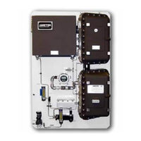
Ametek 931S Operator's Manual (268 pages)
Single/Multi-Gas UV Analyzer
Brand:
Ametek
| Category:
Measuring Instruments
| Size: 17.28 MB
Table of Contents
Offices
2
Table of Contents
3
Electrical Safety
8
Grounding
8
Safety Notes
8
Personnel and Equipment Safety Information
9
Warnings
9
Cautions
10
Warning Labels
11
Environmental Information (WEEE)
11
UV Source Lamps Disposal
11
Electromagnetic Compatibility (EMC)
12
Special Warnings and Information
13
Equipment Used in Class I, Division 2 Hazardous Locations
13
EU Declaration of Conformity
14
Warranty and Claims
16
Chapter 1 Overview
17
About the Analyzer
18
About the Analyzer Sample System
20
Working in this Manual
22
Supplemental Information - Where Can I Find It
23
Chapter 2 Specifications
25
Methodology
25
Standard Range Measuring Cell
25
Response Time
25
Accuracy
25
Repeatability
25
Calibration
26
Linearity
26
Stability
26
Cross-Talk
26
Temperature Drift
26
24-Hour Zero Drift
27
Customer Connections
27
Analog Outputs
27
Status Relay Contacts
27
Digital Communication
27
Electrical Requirements
28
Maximum Start-Up Power
28
Supply Voltage/Maximum Current
28
Maximum Sample Gas Temperature
28
Sample Gas Flow Rate
28
Ambient Limits
29
Temperature
29
Humidity
29
Maximum Altitude
29
Zero Gas
29
Sample Transport
29
Sample Pressure Requirement
29
Instrument Air Requirements
30
Pressure Compensation (Optional)
30
Temperature Control
30
Physical Dimensions (on Backpan)
30
Hydrogen Sensor (Optional)
31
Accuracy
31
Cross-Talk
31
Temperature Drift
31
24-Hour Drift
31
Carbon Dioxide Sensor (Optional)
31
24-Hour Zero Drift
31
Approvals and Certifications
32
ATEX and Iecex Certificates and Analyzer Markings
33
CSA Certificate and Analyzer Marking
41
Chapter 3 Installation and Start-Up
47
Safety Considerations
48
Pre-Installation Requirements
48
Storage Prior to Installation
48
Uncrating and Inspecting the Analyzer
49
General Installation Information
50
Tools and Equipment Required
50
Installing the Mechanical Components
51
Installing the Analyzer
51
Location and Environment
51
Installing the Optical Bench Assembly
53
Installing the Sample System
55
Installing the Optional Heated Acid Gas Sample Probe
55
Installing the Sample and Vent Lines
57
Preparing the Optional Heated Measuring Cell for Operation
57
Installing the Zero/Aspirator Drive Gas Line
58
Electrical Connections
59
Input/Output Signal Connections
60
Digital Input Options
61
Gas Sensor Interface Options
61
Optional Interface Capabilities
61
Digital Communication
62
Hardware Configuration (Modbus Serial Communication)
62
Hardware Configuration (Modbus TCP Communication)
66
Multiple-Analyzer (Multi-Drop) System Configuration
66
AC Power Connection and Fusing
69
European Installation
70
North American Installation
70
S93XS System 200 Configurator Software Installation
72
Minimum PC Requirements for Configurator Software
72
Installing the Configurator Software
73
Removing the Configurator Software
75
Start-Up and Verification
76
Powering up the Analyzer
76
Start-Up Diagnostic Checklist
86
Sample System Leak Check
88
Adjusting Analyzer Controls for Normal Operation
91
Setting the Sample Gas Flow Rate and Sample Response Time
91
Setting the Zero Gas Flow Rate
92
Normal Operation
93
Recording Initial Readings
93
Recording PMT Signals
93
Recording Initial Sample Response Time
94
Analyzer Configuration
95
Chapter 4 Controller / User Interface
97
System 200 Configurator Software Overview - Getting Started
98
Navigating in the Software
98
Starting the Configurator Software and Establishing Communication between the Analyzer and Computer
100
Closing the Configurator Software
102
Configurator Software Troubleshooting
103
General Tab
105
Modbus Serial / Modbus TCP Communication Setup
107
User Interface
110
Setting up the Main Window
110
Viewing Device Activities
111
Restoring Analyzer Configuration Parameters
112
Saving Analyzer Configuration Parameters
112
Modifying Analyzer Device Settings
114
Working from the Setup Tab
114
Printing Analyzer Configuration Parameters
117
Saving Analyzer Configuration Parameters to an ASCII File
117
Refreshing Configuration or Calibration Parameters
118
Saving Configuration or Calibration Parameters to EEPROM
118
Optical Bench
119
Cell/Miscellaneous (Compensations) Parameters
124
Temperature Control
127
Optical Bench Temperature Control
129
Measuring Cell (Oven) Temperature Control (Optional)
130
Heated Acid Gas Sample Probe Temperature Control (Optional)
132
Output Setup
133
Sensors Setup
136
Modbus Settings
142
Matrix
143
Analytical Parameters
144
Analog Inputs
145
Setting Gas Calibration Parameters
147
Alarm Setting and Stream Switch Parameters
153
Analyzer Information
158
Viewing Analyzer Data
160
Status Tab
160
Analyzer Data Tab
166
Optical Bench Data Tab
169
Chapter 5 Calibration
171
Calibrating the Analyzer and Gas Sensors
172
Manual Zero Gas Calibration
173
Manual Span Gas Calibration
174
Sensors Calibration
177
Analog Output Calibration
180
Current Calibration
180
Voltage Calibration
182
Chapter 6 Maintenance and Troubleshooting
185
Safety Considerations
185
Preventive Maintenance
186
Analyzer Preventive Maintenance Schedule
187
Preventing, Detecting, and Locating a Plug in the Sample System
189
Changing out Replaceable Parts
191
Measuring Cell Maintenance
191
Source Lamp Replacement
198
When Do Source Lamps Need to be Replaced
198
About the Source Lamps
199
Replacing the Source Lamps
199
PMT Level and PMT Balance
208
When Is an Auto-Setup Required / Not Required
208
Auto-Setup Fault Message and Corrective Action
210
The Auto-Setup Sequence
210
Cancel Auto-Setup
211
Manipulating the PMT Level and PMT Balance
212
Source Lamp Alignment
214
Chopper Assembly Maintenance - Model 932S Analyzers Only
216
Examining and Caring for the Flamepaths
224
Upper/Lower Electronics Enclosure Flamepaths (Joining Surfaces)
226
Troubleshooting and Diagnostics
227
Host Controller Board Alarm Conditions and Corrective Action
229
Microcontroller Board Alarm Conditions and Corrective Action
240
Analyzer Reset
249
Chapter 7 Service and Parts
251
Technical Support
251
Returning Equipment
252
Answers to Your Questions
253
Ametek Service & Aftermarket Sales Support
253
Recommended Preventive Maintenance Spare Parts
254
Optical Bench Spare Parts
254
Spare Analyzer Fuses
255
Replacement Boards
256
Ordering a Hard Copy of the Analyzer Operator's Guide
256
Appendix A - Drawings
257
Lower Enclosure Layout (WX-14838) - North American (Csa)/European (Zone 1/ATEX
258
Analyzer Wiring Diagram (WX-102860-1
259
TC Sensor Wiring Diagram (WX-102860-2
260
IR Sensor Wiring Diagram (WX-102860-3
261
Optional HMI and Ethernet Gateway Wiring Diagram (WX-102860-4
262
Cable Communications Connections (300-9480
263
Optical Bench Board (100-1662
264
PMT Buffer Board (100-0140
265
Inlet and Vent Flame Arrestor Locations for Environmental Purge Option (100-1783-1A
266
Supplemental Information
267
Advertisement
Advertisement
Related Products
Ametek 930
Ametek 933S
Ametek 932S
Ametek 900
Ametek 9933
Ametek 993-H Series
Ametek 9931
Ametek 9932
Ametek 9931-H
Ametek 9934-H
Ametek Categories
Measuring Instruments
Test Equipment
Power Supply
Controller
Switch
More Ametek Manuals
Login
Sign In
OR
Sign in with Facebook
Sign in with Google
Upload manual
Upload from disk
Upload from URL