Amazone D9 2500 Special Manuals
Manuals and User Guides for Amazone D9 2500 Special. We have 2 Amazone D9 2500 Special manuals available for free PDF download: Operating Manual
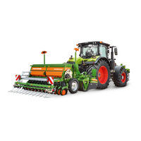
Amazone D9 2500 Special Operating Manual (208 pages)
Seed Drills
Brand: Amazone
|
Category: Farm Equipment
|
Size: 27.43 MB
Table of Contents
-
-
-
Supply Cable43
-
Intended Use46
-
-
Metering63
-
Slide Gate67
-
Bottom Flaps67
-
WS Coulter74
-
Track Marker84
-
Tramlines86
-
6 Start-Up
97 -
8 Settings
114 -
9 Transportation
162 -
-
During Operation170
-
Track Marker172
-
11 Faults
178 -
-
Safety180
-
Lubrication184
-
Advertisement
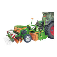
Amazone D9 2500 Special Operating Manual (208 pages)
Seed Drills
Brand: Amazone
|
Category: Farm Equipment
|
Size: 33.36 MB
Table of Contents
-
Supply Cable43
-
Intended Use46
-
Dosing64
-
Bottom Flaps68
-
WS Coulter75
-
Track Marker85
-
Tramlines87
-
Tat102
-
H Tat102
-
Table103
-
Settings115
-
Road Transport164
-
During Operation172
-
Track Marker174
-
Faults180
-
Safety182
-
Lubricating186
Advertisement