Sign In
Upload
Manuals
Brands
Amazone Manuals
Farm Equipment
Cayena 6001-C
Amazone Cayena 6001-C Manuals
Manuals and User Guides for Amazone Cayena 6001-C. We have
2
Amazone Cayena 6001-C manuals available for free PDF download: Operating Manual
Amazone Cayena 6001-C Operating Manual (206 pages)
Brand:
Amazone
| Category:
Farm Equipment
| Size: 10.51 MB
Table of Contents
Table of Contents
5
1 User Information
10
Purpose of the Document
10
Locations in the Operating Manual
10
Diagrams
10
2 General Safety Instructions
11
Obligations and Liability
11
Representation of Safety Symbols
13
Organisational Measures
14
Safety and Protective Equipment
14
Informal Safety Measures
14
User Training
15
Safety Measures in Normal Operation
16
Danger from Residual Energy
16
Maintenance and Repair Work, Fault Elimination
16
Design Changes
17
Spare and Wear Parts and Aids
18
Cleaning and Disposal
18
User Workstation
18
Warning Symbols and Other Labels on the Implement
19
Positions of Warning Symbols and Other Labels
26
Dangers if the Safety Information Is Not Observed
28
Safety-Conscious Working
28
Safety Information for Users
29
General Safety Instructions and Accident Prevention Instructions
29
Hydraulic System
33
Electrical System
34
Attached Implements
34
Brake System
35
Tyres
36
Operation of the Seed Drill
36
PTO Shaft Operation
37
Cleaning, Maintenance and Repair
37
3 Loading and Unloading Road Transport Vehicles
38
Loading the Implement
39
Unloading the Implement
40
4 Product Description
41
Overview of Assembly Groups
42
Safety and Protective Equipment
45
Overview - Supply Lines between the Tractor and the Implement
46
Transportation Equipment
48
Intended Use
50
Danger Areas and Danger Points
51
Rating Plate and CE Mark
52
Technical Data
53
Necessary Tractor Equipment
55
Noise Production Data
55
5 Layout and Function
56
Service Brake System
57
Parking Brake
57
Dual-Circuit Pneumatic Service Brake System
58
Hydraulic Service Brake System
58
Implements Without Independent Service Brake System
58
Accessories Kit with the Operating Manual
59
Radar
59
AMATRON 3 Control Terminal
60
AMADRILL+ Control Terminal
61
Frame and Implement Booms
62
Hopper
63
Fill Level Monitoring
65
Metering
66
One-Chamber System Dosing
67
Two-Chamber System Dosing
68
Application Rate/Calibration Test
69
Seed Pre-Metering (Only with AMATRON 3 Control Terminal)
71
Metering Rollers
72
Metering Roller Diagram Table
73
Blower Fan
76
Connecting the Blower Fan to the Tractor Hydraulics
76
Blower Fan Connection to the Tractor PTO Shaft (On-Board Hydraulic System)
77
Blower Fan Speed Table for Implements with One Hopper Chamber
78
Blower Fan Speed for Implements with Two Hopper Chambers
79
Distributor Head
80
Seed Tube Monitoring (Optional)
80
Coulter Chisel and Seed/Fertiliser Placement Depth
81
Leading Roller Feelers (Optional)
82
Cutting Discs (Optional)
83
Wedge Ring Tyres
84
Furrow Ridge Levellers (Optional)
84
Exact Following Harrow
85
Rear Harrow (Optional)
86
Tractor Wheel Mark Eradicator (Option)
86
Track Markers (Optional)
87
Tramlines
88
Examples for Creating Tramlines
90
Tramline Rhythm 4, 6 and 8
92
Tramline Control 2 and 21
93
One-Sided Switching
94
Tramline Marker (Optional)
94
6 Commissioning
95
Checking the Suitability of the Tractor
96
Calculating the Actual Values for the Total Tractor Weight, Tractor Axle Loads and Load Capacities, as Well as the Minimum Ballast
97
Data Required for the Calculation (Hitched Implement)
98
Calculation of the Required Minimum Ballasting at the Front G Assurance of the Steering Capability
99
Min of the Tractor for
99
Calculation of the Actual Front Axle Load of the Tractor T
99
Calculation of the Actual Total Weight of the Combined Tractor and Implement
99
Tat
99
Calculation of the Actual Rear Axle Load of the Tractor T
99
Tractor Tyre Load Capacity
99
H Tat
99
Table
100
Requirements for Tractor Operation with Attached Implements
101
Securing the Tractor/Implement against Unintentional Start-Up and Rolling
102
Installation Regulations for the Hydraulic Fan Drive Connection
103
7 Coupling and Uncoupling the Implement
104
Dual-Circuit Pneumatic Service Brake System
106
Coupling the Brake and Supply Lines
108
Uncoupling the Supply and Brake Line
110
Control Element of the Dual-Circuit Pneumatic Service Braking System
111
Hydraulic Service Brake System
112
Coupling the Hydraulic Service Brake System
113
Uncoupling the Hydraulic Service Brake System
115
Hydraulic Hose Lines
117
Coupling the Hydraulic Hose Lines
117
Uncoupling the Hydraulic Hose Lines
118
Coupling the Implement to the Tractor
119
Uncoupling the Implement
124
Connect/Disconnect the PTO Shaft Driven Hydraulic Pump
127
Connecting the Hydraulic Pump
127
Uncoupling the Hydraulic Pump
128
8 Settings
129
Setting the Working Depth of the Cutting Discs
130
Repositioning the Fill Level Sensor
131
Installing/Removing the Metering Roller
131
Setting the Spread Rate with a Calibration Test
135
Setting the Blower Fan Speed
137
Setting the Blower Fan Speed Via the Flow Control Valve of the Tractor
138
Setting the Blower Fan Speed on Tractors Without Flow Control Valve
138
Set the Blower Fan Speed When Connecting the Hydraulic Motor to the Tractor PTO Shaft
138
Pressure Relief Valve with Round Outer Contour
139
Basic Setting of the Pressure Relief Valve
139
Blower Fan Speed Setting
139
Pressure Relief Valve with Hexagonal Outer Contour
140
Basic Setting of the Pressure Relief Valve
140
Blower Fan Speed Setting
140
Adjusting the Seed Placement Depth
141
Exact Following Harrow
142
Exact Following Harrow Tine Position
142
Exact Following Harrow Pressure Adjustment
142
Adjusting the Rear Harrow
143
Adjusting the Tractor Wheel Mark Eradicator (on the Field)
143
Track Markers
144
One-Sided Switching
145
Half-Sided Switching off
145
Moving the Tramline Marker to the Working/Transport Position
146
Move the Tramline Marker to Working Position
146
Move the Tramline Markers to the Transport Position
146
Moving the Transport Safety Bar into Transport/Parking Position
147
Moving the Transport Safety Bar to Transport Position
147
Moving the Road Safety Bar into Parking Position
148
9 Transportation
149
Set the Implement to Road Transport Mode
149
Legal Regulations and Safety
150
10 Use of the Implement
154
Work Commencement
156
Unfolding/Folding the Implement Boom
157
Unfolding the Implement Booms
157
Folding the Implement Booms
160
Filling the Hopper
162
Opening/Closing Tarpaulin
163
Opening the Hopper Cover
164
Close the Hopper Cover
165
During the Work
166
Overview of Checks
166
Checking the Placement Depth of the Seed
167
Turning at End of the Field
167
End of Work in the Field
168
Emptying the Hopper And/Or the Metering Unit
169
11 Faults
170
Residual Seed Volume Indicator
170
Deviations between the Preset and Actual Seeding Rates
171
Fault Table
172
12 Cleaning, Maintenance and Repair
173
Fuse
173
Securing the Connected Implement
174
Securing the Lifted Implement
174
Cleaning the Implement
175
Clean the Oil Cooler
176
Clean the Distributor Head
177
Setting and Repair Work (Specialist Workshop)
178
Drawbar Pipe Length Adjustment (Specialist Workshop)
178
Adjusting the Tramline Track Width of the Cultivating Tractor (Specialist Workshop)
179
Adjusting the Tramline Track Width of the Cultivating Tractor (Specialist Workshop)
180
Repairs to the Pressure Tank (Workshop)
182
Lubrication
183
Lubrication Points - Overview
184
Maintenance Schedule - Overview
186
Visual Inspection of the Draw Rail
188
Checking the Tyre Inflation Pressure of the Leading Roller Feelers (Optional)
188
Checking the Tightening Torques of the Wheel and Hub Screws (Specialist Workshop)
188
Check the Inflation Pressure of the Wedge Ring Tyres
189
On-Board Hydraulics - Oil Check and Oil Filter Change
190
Inspection Criteria for Hydraulic Hose Lines before Every Start-Up
192
Inspection Criteria for Hydraulic Hose Lines Using the Maintenance Schedule
192
12.5.7.1 Identification of Hydraulic Hose Lines
193
12.5.7.2 Installing and Removing Hydraulic Hose Lines
194
Service Brake System (All Variants)
195
12.5.8.1 General Visual Inspection of the Service Brake System
195
Checking the Service Brake System for Safe Operating Condition (Specialist Workshop)
195
Service Brake System (Dual-Circuit Pneumatic Service Brake System)
196
12.5.9.1 Exterior Inspection of the Compressed Air Tank
196
Checking the Pressure in the Compressed Air Tank (Specialist Workshop)
196
Leak Tightness Check (Specialist Workshop)
197
Cleaning the Line Filters (Specialist Workshop)
197
Setting the Track Marker for Correct Threading into the Transport Bracket
198
Screw Tightening Torques
199
13 Hydraulic Diagram
200
Hydraulic Diagram Cayena 6001 with AMADRILL
200
Hydraulic Diagram - Cayena 6001(-C) with AMATRON 3
202
Advertisement
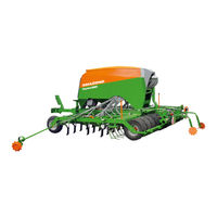
Amazone Cayena 6001-C Operating Manual (207 pages)
Tine coulter seed drill
Brand:
Amazone
| Category:
Farm Equipment
| Size: 28 MB
Table of Contents
User Information
10
General Safety Information
11
Obligations and Liability
11
Representation of Safety Symbols
13
Organisational Measures
14
Safety and Protective Equipment
14
Informal Safety Measures
14
User Training
15
Safety Measures in Normal Operation
16
Danger from Residual Energy
16
Maintenance and Repair Work, Fault Elimination
16
Design Changes
16
Cleaning and Disposal
17
Position of Warning Symbols
25
Dangers in Case of Non-Compliance with the Safety Instructions
27
Safety-Conscious Working
27
Safety Information for Users
28
General Safety Instructions and Accident Prevention Instructions
28
Hydraulic System
32
Electrical System
33
Attached Implements
33
Service Brake System
34
Cleaning, Maintenance and Repair
36
Product Description
40
Transportation Equipment
47
Proper Use
49
Danger Areas and Danger Points
50
Rating Plate and CE Mark
51
Technical Data
53
Required Tractor Equipment
54
Noise Production Data
54
Structure and Function
55
Control Terminal for Implements with ISOBUS System
57
AMAZONE Amatron 4 Control Terminal
57
AMAZONE Twinterminal
58
Parking Brake
59
Hydraulic Service Brake System
60
Implement Documentation
61
Cutting Discs
63
Conveyor Section
68
Distributor Head
84
Seed Tube Monitoring
84
Exact Following Harrow Tine Position
86
Exact Following Harrow Pressure
87
Rear Harrow
87
Track Marker
88
Tramline Rhythm, Tabular Determination
92
Tramline Rhythm, Graphic Determination
92
One-Sided Switching
94
Tramline Marker
95
Initial Operation
96
Checking the Suitability of the Tractor
97
Secure the Tractor / Implement against Unintentional Starting and Rolling Away
103
Coupling and Uncoupling the Implement
105
Coupling the Hydraulic Service Brake System
111
Uncoupling the Hydraulic Service Brake System
113
Coupling the Hydraulic Hose Lines
115
Uncoupling the Hydraulic Hose Lines
116
Uncoupling the Implement
122
Adjusting the Fan Speed
134
Pressure Relief Valve with Round Outer Contour
136
Pressure Relief Valve with Hexagonal Outer Contour
137
Adjusting the Rear Harrow
141
Moving the Road Safety Bar into Parking Position
146
Maximum Permissible Speed
149
Use of the Implement
152
Filling the Hopper
163
During Operation
167
Check Points
167
End of Work on the Field
169
Fault Table
172
Maintenance and Repairs
173
Visual Inspections
181
Installations
188
Checking the Hydraulic Hose Lines
193
Oils and Greases
197
Bolt Tightening Torques
198
Hydraulic Diagram
200
Advertisement
Related Products
Amazone Cayena 6001
Amazone Certos 6001-2TX
Amazone Cirrus 6002
Amazone Precea 6000-2
Amazone Precea 6000-2CC
Amazone Precea 6000-2FCC
Amazone Precea 6000
Amazone Precea 6000-CC
Amazone Precea 6000-FCC
Amazone Certos 6002-2TX
Amazone Categories
Farm Equipment
Tiller
Spreader
Desktop
Paint Sprayer
More Amazone Manuals
Login
Sign In
OR
Sign in with Facebook
Sign in with Google
Upload manual
Upload from disk
Upload from URL