
Related Manuals for Amazone Cayena 6001


Summary of Contents for Amazone Cayena 6001
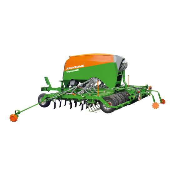
- Page 1 Operating Manual Cayena 6001 Cayena 6001-C Please read this operating manual before commissioning. Keep it in a safe place for future use! MG4235 BAH0062-4 09.15...
- Page 2 Reading the instruction manual and to adhere to it should not appear to be inconvenient and superfluous as it is not enough to hear from others and to realise that a machine is good, to buy it and to believe that now everything would work by itself.
- Page 3 + 49 (0) 5405 501-234 E-mail: amazone@amazone.de Spare part orders Spare parts lists are freely accessible in the spare parts portal at www.amazone.de. Please send orders to your AMAZONE dealer. Formalities of the operating manual Type: Cayena Document number: MG4235 Compilation date: 09.15...
- Page 4 Foreword Dear Customer, You have chosen one of the quality products from the wide product range of AMAZONEN-WERKE, H. DREYER GmbH & Co. KG. We thank you for your trust in our products. On receiving the implement, check to see if it has been damaged during transport or if parts are missing.
-
Page 5: Table Of Contents
User information ..................10 Purpose of the document ....................... 10 Locations in the operating manual ..................10 Diagrams ..........................10 General Safety Instructions ..............11 Obligations and liability ......................11 ... - Page 6 5.1.4 Implements without independent service brake system ............58 Accessories kit with the operating manual ................59 Radar ............................. 59 AMATRON 3 control terminal ....................60 AMADRILL+ control terminal....................61 ...
- Page 7 7.1.1 Coupling the brake and supply lines ..................108 7.1.2 Uncoupling the supply and brake line .................. 110 7.1.3 Control element of the dual-circuit pneumatic service braking system ....... 111 Hydraulic service brake system ................... 112 ...
- Page 8 12.6 Screw tightening torques ..................... 199 Hydraulic diagram ................... 200 13.1 Hydraulic diagram Cayena 6001 with AMADRILL+ ............200 13.2 Hydraulic diagram – Cayena 6001(-C) with AMATRON 3 ..........202 Cayena BAH0062-4 09.15...
- Page 9 Cayena BAH0062-4 09.15...
-
Page 10: User Information
User information User information The User Information section provides information on use of the operating manual. Purpose of the document This operating manual describes the operation and maintenance of the implement. provides important information on safe and efficient handling of the implement. -
Page 11: General Safety Instructions
General Safety Instructions General Safety Instructions This section contains important information on safe operation of the implement. Obligations and liability Comply with the instructions in the operating manual Knowledge of the basic safety information and safety regulations is a basic requirement for safe handling and fault-free implement operation. - Page 12 General Safety Instructions Risks in handling the implement The implement has been constructed to the state-of-the art and the recognised rules of safety. However, operating the implement may cause risks and restrictions to the health and safety of the user or third persons. ...
-
Page 13: Representation Of Safety Symbols
General Safety Instructions Representation of safety symbols Safety instructions are indicated by the triangular safety symbol and the highlighted signal word. The signal word (DANGER, WARNING, CAUTION) describes the severity of the risk, and carries the following meaning: DANGER Indicates a direct threat at high risk which will result in death or most serious bodily harm (loss of limbs or long-term harm), should it not be prevented. -
Page 14: Organisational Measures
General Safety Instructions Organisational measures The operator must provide the necessary personal protective equipment as per the information provided by the manufacturer of the crop protection agent to be used, such as: Safety glasses Protective shoes Chemical-resistant overalls ... -
Page 15: User Training
General Safety Instructions User training Only those people who have been trained and instructed may work with/on the implement. The operator must clearly specify the responsibilities of the people charged with operation and maintenance work. People being trained may only work with/on the implement under the supervision of an experienced person. -
Page 16: Safety Measures In Normal Operation
General Safety Instructions Safety measures in normal operation Only operate the implement if all the safety and protection equipment is fully functional. Check the implement at least once a day for visible damage and check the function of the safety and protection equipment. Danger from residual energy Note that there may be residual mechanical, hydraulic, pneumatic and electrical/electronic energy on the implement. -
Page 17: Design Changes
General Safety Instructions 2.10 Design changes You may make no changes, expansions or modifications to the implement without the authorisation of AMAZONEN-WERKE. This also applies when welding support parts. Any expansion or modification work shall require the written approval of AMAZONEN-WERKE. Only use modification and accessory parts approved by AMAZONEN-WERKE so that the type approval, for example, remains valid in accordance with national and international regulations. -
Page 18: Spare And Wear Parts And Aids
Immediately replace any implement parts which are not in a perfect state. Use only genuine AMAZONE spare and wear parts or the parts cleared by AMAZONEN-WERKE so that the operating permit retains its validity in accordance with national and international regulations. If... -
Page 19: Warning Symbols And Other Labels On The Implement
General Safety Instructions 2.13 Warning symbols and other labels on the implement Always keep all the warning symbols of the implement clean and in a legible state. Replace illegible warning symbols. You can obtain the warning symbols from your dealer using the order number (e.g., MD 075). - Page 20 General Safety Instructions Order number and explanation Warning symbols MD 076 Risk of drawing-in/entrapment for hand or arm due to moving force-transmission parts! This hazard can cause the most severe injuries with loss of body parts. Never open or remove protective equipment, ...
- Page 21 General Safety Instructions MD 084 Risk of crushing the entire body due to standing in the swivel range when implement parts are being lowered. Causes serious, potentially fatal injuries anywhere on the body. It is forbidden to stand in the swivel range of the implement when implement parts are being lowered.
- Page 22 General Safety Instructions MD 097 Risk of crushing the entire body by entering/remaining in the stroke area of the three-point suspension when the three-point hydraulic system is operated! Causes serious, potentially fatal injuries anywhere on the body. Personnel are prohibited from standing in the stroke area of the three-point suspension when the three-point hydraulic system is operated.
- Page 23 General Safety Instructions MD 104 Risk of crushing the entire body or impacts due to standing in the swivel range of laterally moving implement parts. These dangers can cause extremely serious and potentially fatal injuries. Maintain an adequate safety distance from moving implement parts while the tractor engine is running.
- Page 24 General Safety Instructions MD 154 Danger of cuts for other road users caused by transport with unguarded, sharp harrow tines of the seed harrow! Causes serious, potentially fatal injuries anywhere on the body. Transportation without a correctly fitted transport safety bar is forbidden. Install the transport safety bar provided before starting transportation.
- Page 25 General Safety Instructions MD 191 Warning: Radiation from radar. Risk to the whole body from radar radiation. When radar sensors are switched on, maintain a safe distance of 2 metres. MD 199 The maximum operating pressure of the hydraulic system is 210 bar. MD 225 Risk of crushing of the entire body due to standing in the swivel range of the drawbar...
-
Page 26: Positions Of Warning Symbols And Other Labels
General Safety Instructions 2.13.1 Positions of warning symbols and other labels Warning symbols The following diagrams show the arrangement of the warning symbols on the implement. Fig. 1 Fig. 2 Cayena BAH0062-4 09.15... - Page 27 General Safety Instructions Fig. 3 Fig. 4 Fig. 5 Fig. 6 Fig. 7 Cayena BAH0062-4 09.15...
-
Page 28: Dangers If The Safety Information Is Not Observed
General Safety Instructions 2.14 Dangers if the safety information is not observed Non-compliance with the safety information can pose both a danger to people and to the environment and implement. can lead to the loss of all warranty claims. In particular, non-compliance with the safety information could pose the following risks: ... -
Page 29: Safety Information For Users
General Safety Instructions 2.16 Safety information for users WARNING Risk of crushing, cutting, being trapped or drawn in, or impact through inadequate roadworthiness and operational safety. Before starting up the implement and the tractor each time, always check their traffic and operational safety. CAUTION Switch off the control terminal ... - Page 30 General Safety Instructions The approved load capacities of the tractor tyres Secure the tractor and the implement against unintentional rolling before coupling or uncoupling the implement. It is forbidden for people to stand between the implement to be coupled and the tractor while the tractor is approaching the implement.
- Page 31 General Safety Instructions Use of the implement Before starting work, ensure that you understand all the equipment and actuation elements of the implement and their function. There is no time for this when the implement is already in operation! ...
- Page 32 General Safety Instructions Always fix the front or rear weights to the intended fixing points according to regulations. Comply with the maximum load of the connected implement and the approved axle and support loads of the tractor. The tractor must guarantee the prescribed brake delay for the loaded vehicle combination (tractor plus connected implement).
-
Page 33: Hydraulic System
Replace the hydraulic hose lines if they are damaged or worn. Use only genuine AMAZONE hydraulic hose lines! The hydraulic hose lines should not be used for longer than six years, including any storage time of maximum two years. Even... -
Page 34: Electrical System
General Safety Instructions 2.16.3 Electrical system When working on the electrical system, always disconnect the battery (negative terminal). Only use the prescribed fuses. If fuses are used that are too highly rated, the electrical system will be destroyed – risk of fire. ... -
Page 35: Brake System
General Safety Instructions 2.16.5 Brake system Only specialist workshops or recognised brake services can carry out adjustment and repair work on the brake system. Have the brake system checked regularly. If there are any functional faults in the brake system, stop the tractor immediately. -
Page 36: Tyres
General Safety Instructions Hydraulic brake system for export implements Hydraulic brake systems are not approved in Germany. When filling up or replacing the brake fluid, use the prescribed hydraulic fluids. When replacing the hydraulic fluids, comply with the appropriate regulations. 2.16.6 Tyres ... -
Page 37: Pto Shaft Operation
Disconnect the cable to the tractor generator and battery, before carrying out electrical welding work on the tractor and on attached implements. Spare parts must meet at least the specified technical requirements of AMAZONEN-WERKE! This is ensured through the use of original AMAZONE spare parts. Cayena BAH0062-4 09.15... -
Page 38: Loading And Unloading Road Transport Vehicles
Loading and unloading road transport vehicles Loading and unloading road transport vehicles WARNING There is a risk of an accident when the tractor is unsuitable and the implement brake system is not connected to the tractor or is filled. Important for correct handling of the implement during loading and unloading: ... -
Page 39: Loading The Implement
Loading and unloading road transport vehicles Loading the implement 1. Move the implement to the transport position. 2. Raise the implement via the integrated running gear. 3. Push the implement carefully backwards onto the transport vehicle. A marshalling person is required for loading. -
Page 40: Unloading The Implement
Loading and unloading road transport vehicles Unloading the implement 1. Couple the implement to the tractor. 2. Remove the transport securing device (lashing straps). 3. Raise the implement using the integrated running gear and pull it carefully off of the transport vehicle. -
Page 41: Product Description
Product description Implement designations Cayena with one chamber hopper Cayena with two chamber hopper and folding booms and folding booms Cayena 6001 Cayena 6001-C Main assemblies of the implement Fig. 12 (1) Hopper (5) Wedge ring tyres with integrated running... -
Page 42: Overview Of Assembly Groups
Product description Overview of assembly groups Fig. 13/... (1) Case for stowing of the operating manual of the dosing rollers of the digital scale Fig. 13 Fig. 14/... AMADRILL+ control terminal (optional) Fig. 14 Fig. 15/... AMATRON 3 control terminal (optional) Fig. - Page 43 Product description Fig. 16/... (1) Draw rail (2) Drawbar, extendable (3) Stand, foldable (4) Step Fig. 16 Fig. 17/... Bracket with hose cabinet Fig. 17 Fig. 18/... (1) Metering unit (2) Electric motor (dosing roller drive) Fig. 18 Fig. 19/... Coulter chisel Fig.
- Page 44 Product description Fig. 20/... Blower fan with oil cooler (oil cooler only in combination with power take-off) Fig. 20 Fig. 21/... Roller feeler (optional) Fig. 21 Fig. 22/... Cutting discs (optional) Fig. 22 Fig. 23/... Tractor wheel mark eradicator (option) Fig.
-
Page 45: Safety And Protective Equipment
Product description Safety and protective equipment Fig. 24/… (1) Blower fan guard screen Fig. 24 Fig. 25/… (1) Sieves (serves as a guard screen in the hopper) Fig. 25 Fig. 26/… (1) Implement boom lock for transportation Fig. 26 Cayena BAH0062-4 09.15... -
Page 46: Overview - Supply Lines Between The Tractor And The Implement
Product description Overview – Supply lines between the tractor and the implement Power supply cable Designation Function Implement connector Control terminal Plug (7-pin) Road traffic lighting system Service brake system Designation Marking Function Brake line Yellow Dual-circuit pneumatic service brake system Supply line Hydraulic brake line (optional) - Page 47 Product description With AMADRILL+ control terminal Hydraulic hose Tractor rear Function Note labelling control unit Running gear and Lift cutting discs Double- Yellow acting Running gear and Lower cutting discs Track marker Lift Pre- Implement booms, foldable Lift selection on Double- Green the valve...
-
Page 48: Transportation Equipment
Product description Transportation equipment Fig. 28/... (1) 8 road safety bars for covering the harrow tines the coulter chisels (2) 2 rear-facing warning signs Fig. 28 Fig. 29/... (1) 2 road safety bars to cover the rear harrow tines Fig. - Page 49 Product description Fig. 31/... (1) 2 forwards-facing warning signs (2) 2 forwards-facing limiting lights Fig. 31 Fig. 32/... (1) 2 x 3 reflectors, yellow, (laterally with a max. spacing of 3 m) Fig. 32 Cayena BAH0062-4 09.15...
-
Page 50: Intended Use
Compliance with all the instructions in this operating manual. Adherence of inspection and maintenance work. Exclusive use of original AMAZONE spare parts. Other uses to those specified above are forbidden and shall be considered as improper. For any damage resulting from improper use ... -
Page 51: Danger Areas And Danger Points
Product description Danger areas and danger points The danger area is the area around the implement in which people can be caught: by work movements made by the implement and its tools. by materials or foreign bodies thrown out of the implement. ... -
Page 52: Rating Plate And Ce Mark
Product description Rating plate and CE mark The diagram shows the position (Fig. 33/1) of the rating plate and the CE mark on the implement. The CE marking on the indicates compliance with the stipulations of the valid EU directives. Fig. -
Page 53: Technical Data
Product description Technical data Cayena 6001 Cayena 6001-C Working width Row spacing of the coulter [cm] 16.6 16.6 Number of sowing units Number of hopper chambers [number] Chamber, front 2400 Hopper volume 3600 Chamber, rear 1600 Payload (on the field) - Page 54 Product description Road transport data (only with an empty hopper!) Cayena 6001 Cayena 6001-C Total width (in transport position) Total length (in transport position) 6.71 6.71 Total height (in transport position) Basic weight [kg] see rating plate Permissible total weight...
-
Page 55: Necessary Tractor Equipment
Product description Necessary tractor equipment For operation of the implement in compliance with the intended use, the tractor must fulfil the following requirements. Power Cayena 6001 100 kW/136 hp requirement Cayena 6001-C Battery voltage 12 V (volts) Electrical system Lighting socket 7-pin see section 4.3,... -
Page 56: Layout And Function
The Cayena tine seed drill allows seeding in a single work process, with or without previous soil tillage. The coulter chisels (Fig. 35/1) are also suitable for seeding on harder soils that are sometimes unsuitable for traditional coulters. The Cayena 6001 tine seed drill has a one- chamber hopper, the Cayena 6001-C a two- chamber hopper. -
Page 57: Service Brake System
Layout and function The seed placement depth is adjustable. After placement, the seed is covered with loose soil by the exact following harrow (Fig. 35/5). The rear harrow (optional) is used as a complement. The track markers (Fig. 35/6) mark the field connection run in the centre of the tractor. Before germination of the seed, the tramline marker (Fig. -
Page 58: Dual-Circuit Pneumatic Service Brake System
Layout and function 5.1.2 Dual-circuit pneumatic service brake system In Germany, the implement is equipped with a dual-circuit pneumatic service braking system. The dual-circuit pneumatic service brake system controls two brake cylinders, which actuate the brake shoes in the brake drums. The tractor also has to be equipped with a dual-circuit pneumatic service brake system. -
Page 59: Accessories Kit With The Operating Manual
Layout and function Accessories kit with the operating manual The cases (Fig. 39/1) contain: the pack with the operating manual, the dosing rollers in parking position, the scales for the calibration test. Fig. 39 Radar The radar (Fig. 40/1) is used to record the working speed. -
Page 60: Amatron 3 Control Terminal
Layout and function AMATRON 3 control terminal The AMATRON 3 consists of the control terminal (Fig. 41), the basic equipment (cable and fastening materials), and the job computer on the implement. The AMATRON 3 controls and monitors seed drills with one- and two-chamber systems. Fig. -
Page 61: Amadrill+ Control Terminal
Layout and function AMADRILL+ control terminal The AMADRILL+ consists of the control terminal and the basic equipment (cable and fastening materials). The AMADRILL + is used for seed drills with one chamber system. The control valve (Fig. 44/Fig. 45) is used to pre- select the hydraulic function. -
Page 62: Frame And Implement Booms
Layout and function Frame and implement booms Fig. 46 The implement has a main frame (Fig. 46/1) with integrated running gear (Fig. 46/2). a hopper with one chamber or two chambers. two implement booms which are retractable for transportation purposes (Fig. 46/3). Cayena BAH0062-4 09.15... -
Page 63: Hopper
Layout and function Hopper The Cayena 6001 tine seed drill has a one chamber hopper, the Cayena 6001-C a two chamber hopper. One chamber hopper The hopper with one chamber is closed using a roller tarpaulin (Fig. 47/1) to protect against dust and rain. - Page 64 Layout and function The pressure gauge (Fig. 50/1) shows the overpressure in the closed delivery system. Fig. 50 The interior lighting (Fig. 51/1) of the hopper is coupled with the driving light of the tractor. Fig. 51 Cayena BAH0062-4 09.15...
-
Page 65: Fill Level Monitoring
Layout and function 5.7.1 Fill level monitoring Each chamber is equipped with a filling level sensor (Fig. 52/1) for monitoring the hopper content. When the level in the chamber reaches the filling level sensor, the control terminal indicates a warning message and outputs an alarm signal at the same time. -
Page 66: Metering
Layout and function Metering The hopper is equipped with one or two chambers. Each chamber is equipped with a metering unit. The seed is metered by a metering roller in the metering unit. The metering roller (Fig. 53/1) can be replaced. Fig. -
Page 67: One-Chamber System Dosing
Layout and function 5.8.1 one-chamber system dosing Implements with one hopper chamber have one metering unit (Fig. 55). Fig. 55 For the calibration test and for emptying, the seed falls through an opening in the floor of the injector sluice (Fig. 56/1). A rotary shutter closes the opening. -
Page 68: Two-Chamber System Dosing
Layout and function 5.8.2 Two-chamber system dosing For implements with two hopper chambers, metering is only possible with the AMATRON 3. For implements with two hopper chambers, there is a metering unit under each chamber (Fig. 58/1). The metering units are numbered. Metering unit 1 is connected to the rear chamber. -
Page 69: Application Rate/Calibration Test
Layout and function 5.8.3 Application rate/Calibration test The calibration test is used to determine the metering roller speed for the desired spread rate. The weight of the seed quantity collected from the first calibration test is required. A second calibration test is essential. The required seed quantity is usually applied during the second calibration test. - Page 70 Layout and function A digital scale is include in the scope of delivery. Fig. 61 The icon (Fig. 62/1) marks the holder for the digital scale. The holder is used to hang the digital scale during the calibration test. Fig. 62 Cayena BAH0062-4 09.15...
-
Page 71: Seed Pre-Metering (Only With Amatron 3 Control Terminal)
Layout and function 5.8.4 Seed pre-metering (only with AMATRON 3 control terminal) Seed pre-metering, which meters the seed in the air flow, can be activated on the control terminal before the implement starts up. Seed pre-metering is used when corners are to be sowed which can only be reached when the implement is reversed. -
Page 72: Metering Rollers
Layout and function 5.8.5 Metering rollers The metering roller selection for the seed and fertiliser depends on the grain size, spread rate. You can choose between metering rollers with various chamber sizes or different volumes (see page 73 to page 75). You must select a metering roller volume that is not too large but that is sufficient to spread the required quantity (kg/ha). -
Page 73: Metering Roller Diagram Table
Layout and function 5.8.5.1 Metering roller diagram table 7.5 cm 20 cm 40 cm 120 cm Cayena BAH0062-4 09.15... - Page 74 Layout and function 210 cm 350 cm 600 cm 660 cm Metering rollers with different capacities are available. Select the metering roller required depending on the seed or the fertiliser and the spread rate according to the following tables. If the seed is not listed, select the metering roller of a seed that has a similar grain size.
- Page 75 Layout and function 5.8.5.2 Table – metering rollers, seed Metering rollers Seed 7,5 cm³ 20 cm³ 40 cm³ 120 cm³ 210 cm³ 350 cm³ 600 cm³ 660 cm³ Beans Spelt Peas Flax (dressed) Barley Grass seed Oats Millet Lupins Alfalfa Maize Poppy seed Oil linen...
-
Page 76: Blower Fan
Layout and function Blower fan The blower fan that creates the air current is driven by a hydraulic motor (Fig. 67/1). The air current carries the seed to the coulters. The blower fan speed determines the air volume of the air current. The higher the blower fan speed, the greater is the air volume generated. -
Page 77: Blower Fan Connection To The Tractor Pto Shaft (On-Board Hydraulic System)
Layout and function 5.9.2 Blower fan connection to the tractor PTO shaft (on-board hydraulic system) The on-board hydraulic system (optional) consists of a hydraulic pump and a hydraulic motor that drives the blower fan. The hydraulic pump (Fig. 69/1) is driven by the tractor PTO shaft. -
Page 78: Blower Fan Speed Table For Implements With One Hopper Chamber
Fine seed types (2), e.g. rape or grass seed. Grain and legumen (3). Example: Cayena 6001 Working width 6.0 m (1). Cereal seed (3). required blower fan speed: 3900 rpm Fig. 72 Cayena BAH0062-4 09.15... -
Page 79: Blower Fan Speed For Implements With Two Hopper Chambers
Layout and function 5.9.4 Blower fan speed for implements with two hopper chambers For implement with two hopper chambers, an overpressure is generated in the hopper when the blower fan is running. The pressure gauge (Fig. 73/1) indicates the overpressure. The overpressure varies at a constant blower fan speed depending on the quantity of seed/fertiliser and on the working speed. -
Page 80: Distributor Head
Layout and function 5.10 Distributor head In the distributor head (Fig. 75/1), the seed is distributed uniformly over all the coulters. Fig. 75 5.10.1 Seed tube monitoring (optional) The seed tube hoses represent the connection between the distributor head and the coulters. Each seed tube hose can be equipped with a sensor (Fig. -
Page 81: Coulter Chisel And Seed/Fertiliser Placement Depth
Layout and function 5.11 Coulter chisel and seed/fertiliser placement depth Check the placement depth after each adjustment. The coulter chisel optimises area efficiency and ensures long service life. For seed/fertiliser placement, the "on grip" coulter chisels penetrate into the soil. In this way the coulter chisels, supported on the trailing wedge ring roller and the tractor lower links, maintain the adjustable seed and fertiliser... -
Page 82: Leading Roller Feelers (Optional)
Layout and function The depth of individual coulters working in the tractor track can be adjusted. Reposition the coulters accordingly in the hole pattern (Fig. 81/1) . Fig. 81 5.12 Leading roller feelers (optional) For seed placement, the "on grip" coulter chisels penetrate into the soil. -
Page 83: Cutting Discs (Optional)
Layout and function 5.13 Cutting discs (optional) The cutting discs cut any remaining crops and growth. The hydraulic cylinders of the cutting discs are connected to the hydraulic cylinders of the integrated running gear. If the implement is raised before turning at the end of the field, the cutting discs are also raised out of the ground. -
Page 84: Wedge Ring Tyres
Layout and function 5.14 Wedge ring tyres The wedge ring tyres are arranged adjacent to each other. compact the cultivated soil, in which the seed will be placed, in strips. form the integrated running gear during transportation and when turning at the end of a field. -
Page 85: Exact Following Harrow
Layout and function 5.15 Exact following harrow The exact following harrow (Fig. 88/1) evenly covers the seeds deposited in the seed furrows with loose earth and smoothes the ground. The following are adjustable the position of the harrow tines, ... -
Page 86: Rear Harrow (Optional)
Layout and function 5.16 Rear harrow (optional) The rear harrow (Fig. 91/1) throws loose soil onto the compacted strips for an even surface appearance. The following are adjustable the angle at which the harrows penetrate the ground. the penetration depth of the harrows in the ground. -
Page 87: Track Markers (Optional)
Layout and function 5.18 Track markers (optional) The hydraulically-actuated markers dig into the ground alternately on the left and the right of the implement. In so doing, the active track marker creates a mark. This mark serves as an orientation aid for the next run after turning. -
Page 88: Tramlines
Layout and function 5.19 Tramlines Tramlines can be created on the field. Tramlines are seed-free tracks for fertilising and plant care implement used later. Fig. 95 When creating the tramlines sliders (Fig. 96/1) in the distributor head block the seed supply to the seeding line tubes (Fig. - Page 89 Layout and function The tramline selection allows the creation of tramlines (A) at pre-selected intervals on the field. The tramline spacing (b) corresponds to the working width of the cultivating machines (B), e.g. fertiliser spread and/or sprayer, which are used on sown fields. Fig.
-
Page 90: Examples For Creating Tramlines
Layout and function Seed drill working width 6.0 m Tramline spacing Tramline rhythm (working width of the fertiliser spreader and field sprayer) 12 m 18 m 24 m 30 m 36 m 42 m 24 m 36 m Fig. 98 5.19.1 Examples for creating tramlines The creation of tramlines is shown using various examples (see Fig. - Page 91 Layout and function Fig. 99 Cayena BAH0062-4 09.15...
-
Page 92: Tramline Rhythm 4, 6 And 8
Layout and function 5.19.2 Tramline rhythm 4, 6 and 8 Fig. 100 The tramline rhythm 4, 6 and 8 require the work with the seed drill at half width (partial width) during the first field run. Another option for creating tramlines with the tramline rhythm 4, 6 and 8 is to begin with the full working width and the creation of a tramline (see Fig. -
Page 93: Tramline Control 2 And 21
Layout and function 5.19.3 Tramline control 2 and 21 Fig. 101 When tramlines are created with the tramline rhythm 2 plus and 21 plus, tramlines are created during the trips forward and backward over the field. The seed feed to the tramline coulters may be interrupted by the implement with ... -
Page 94: One-Sided Switching
Layout and function 5.19.4 One-sided switching Fig. 102 During the first field run, e.g., tramline rhythm 4 requires the work of the seed drill at half working width. The coulter on the left side of the implement does not place seeds in the soil. The installation of an insert (Fig. -
Page 95: Commissioning
Commissioning Commissioning This section contains information on initial operation of your implement. on how to check if you may mount/couple the implement on/to your tractor. Before operating the implement for the first time the operator must have read and understood the operating manual. ... -
Page 96: Checking The Suitability Of The Tractor
Commissioning Checking the suitability of the tractor WARNING Danger of breaking during operation, insufficient stability and insufficient tractor steering and braking power on improper use of the tractor! Check the suitability of your tractor before you mount or hitch the implement onto the tractor. -
Page 97: Calculating The Actual Values For The Total Tractor Weight, Tractor Axle Loads And Load Capacities, As Well As The Minimum Ballast
Commissioning 6.1.1 Calculating the actual values for the total tractor weight, tractor axle loads and load capacities, as well as the minimum ballast The approved total tractor weight, specified in the vehicle documentation, must be greater than the sum of the ... -
Page 98: Data Required For The Calculation (Hitched Implement)
Commissioning 6.1.1.1 Data required for the calculation (hitched implement) Fig. 105 [kg] Tractor empty weight See tractor operating manual or vehicle documentation [kg] Front axle load of the empty tractor [kg] Rear axle load of the empty tractor [kg] Front weight (if available) See technical data of the front weight, or weigh [kg] Maximum drawbar load... -
Page 99: Calculation Of The Required Minimum Ballasting At The Front G Assurance Of The Steering Capability
Commissioning 6.1.1.2 Calculation of the required minimum ballasting at the front G of the tractor for V min assurance of the steering capability Enter the numeric value for the calculated minimum ballast G V min required on the front side of the tractor, in the table (section 6.1.1.7). -
Page 100: Table
Commissioning 6.1.1.7 Table Actual value according to Approved value Double approved calculation according to tractor load capacity (two instruction manual tyres) Minimum ballast front/rear Total weight Front axle load Rear axle load You can find the approved values for the total tractor weight, axle loads and load capacities in the tractor registration papers. -
Page 101: Requirements For Tractor Operation With Attached Implements
Commissioning 6.1.2 Requirements for tractor operation with attached implements WARNING Risk of breakage during operation of components through unapproved combinations of connecting equipment! Ensure: that the connection device on the tractor has a sufficient permissible noseweight for the noseweight actually in question. ... -
Page 102: Securing The Tractor/Implement Against Unintentional Start-Up And Rolling
Commissioning Securing the tractor/implement against unintentional start-up and rolling WARNING Risk of crushing, shearing, cutting, being caught and/or drawn in, or impact when making interventions in the implement, through unintentional lowering of the unsecured implement when it is raised via the three-point hydraulic system of the tractor. ... -
Page 103: Installation Regulations For The Hydraulic Fan Drive Connection
Commissioning Installation regulations for the hydraulic fan drive connection The back pressure of 10 bar must not be exceeded. The installation regulations therefore have to be complied with when connecting the hydraulic fan connection. Connect the hydraulic coupling of the pressure hose (Fig. 106/5) to a single-acting or double- acting tractor control unit with priority. -
Page 104: Coupling And Uncoupling The Implement
Coupling and uncoupling the implement Coupling and uncoupling the implement When coupling and uncoupling implements, follow the instructions given in the section "Safety instructions for the operator". CAUTION Switch off the control terminal before road transport. before adjustment, maintenance and repair work. Risk of accident due to unintended movements of the metering unit or other implement components caused by radar pulses. - Page 105 Coupling and uncoupling the implement DANGER If the tractor has been separated from the implement, always secure with 2 wheel chocks. the parking brake (if fitted) of the implement. The implement may only be uncoupled from the tractor after being secured using 2 wheel chocks and with the implement parking brake applied (if fitted).
-
Page 106: Dual-Circuit Pneumatic Service Brake System
Coupling and uncoupling the implement Dual-circuit pneumatic service brake system DANGER Before uncoupling the implement from the tractor, secure it with wheel chocks and apply the implement's parking brake. Only remove the wheel chocks once the implement has been coupled up to the tractor. Then release the implement's parking brake. - Page 107 Coupling and uncoupling the implement The dual-circuit pneumatic service brake system has: A supply line (Fig. 107/1) with coupling head (red) A brake line (Fig. 107/2) with coupling head (yellow) Fig. 107 Once the implement has been properly coupled, the implement service braking system responds when the tractor brake pedal and the tractor parking brake are applied.
-
Page 108: Coupling The Brake And Supply Lines
Coupling and uncoupling the implement 7.1.1 Coupling the brake and supply lines WARNING Risk of contusions, cuts, dragging, catching or knocks from incorrectly functioning brake system. When coupling the brake and supply line, ensure that: the sealing rings of the hose couplings are clean. ... - Page 109 Coupling and uncoupling the implement 1. Check if the implement is secured with 2 wheel chocks and the implement parking brake is applied. 2. Couple the implement to the tractor. 3. Apply the tractor parking brake, switch off the tractor engine, and remove the ignition key. 4.
-
Page 110: Uncoupling The Supply And Brake Line
Coupling and uncoupling the implement 7.1.2 Uncoupling the supply and brake line DANGER Before uncoupling the implement from the tractor, secure it with 2 wheel chocks and apply the implements parking brake. WARNING Risk of crushing, cutting, being caught or drawn in, or impact through the accidentally rolling implement, if the service brake is released. -
Page 111: Control Element Of The Dual-Circuit Pneumatic Service Braking System
Coupling and uncoupling the implement 3. Release the hose coupling (Fig. 111) of the supply line (red). 4. Release the hose coupling of the brake line (yellow). 5. Fasten the hose couplings in the idle coupling points. 6. Close the tractor hose couplings caps. Fig. -
Page 112: Hydraulic Service Brake System
Coupling and uncoupling the implement Hydraulic service brake system WARNING If the hydraulic socket is decoupled from the tractor, the service brake system of the implement has no braking effect. Before uncoupling the implement from the tractor, secure it with 2 wheel chocks and apply the implements parking brake. -
Page 113: Coupling The Hydraulic Service Brake System
Coupling and uncoupling the implement 7.2.1 Coupling the hydraulic service brake system Only couple clean hydraulic sockets and connectors. DANGER Check the routing of the brake line. The brake line must not chafe on foreign parts. The braking effect of the implement service brake system is not immediately available after coupling the hydraulic socket to the tractor. - Page 114 Coupling and uncoupling the implement 6. Connect the break-away valve to the tractor via the cable (Fig. 115/1). If the implement is separated from the tractor due to an accident, the implement will be braked. Fig. 115 7. Fill the hydro reservoir (Fig. 116/1) before moving off.
-
Page 115: Uncoupling The Hydraulic Service Brake System
Coupling and uncoupling the implement 7.2.2 Uncoupling the hydraulic service brake system WARNING If the hydraulic socket is decoupled from the tractor, the service brake system of the implement has no braking effect. Before uncoupling the implement from the tractor, secure it with 2 wheel chocks and apply the implements parking brake. - Page 116 Coupling and uncoupling the implement 3. Empty the hydro accumulator. 3.1 Actuate the valve (Fig. 119/1). This drains the hydro reservoir. Fig. 119 4. Uncouple the hydraulic socket. The hydraulic socket cannot be coupled to the tractor again unless the hydro accumulator is empty.
-
Page 117: Hydraulic Hose Lines
Coupling and uncoupling the implement Hydraulic hose lines WARNING Danger of infection from escaping hydraulic fluid at high pressure! When coupling and uncoupling the hydraulic hose lines, ensure that the hydraulic system is depressurized on both the implement and tractor sides. If you are injured by hydraulic fluid, contact a doctor immediately. -
Page 118: Uncoupling The Hydraulic Hose Lines
Coupling and uncoupling the implement 1. Put all tractor control units in float position. 2. Clean the coupling part. 3. Connect the hydraulic lines to the tractor control units (markings of the hydraulic lines, see section 4.3). Fig. 121 7.3.2 Uncoupling the hydraulic hose lines 1. -
Page 119: Coupling The Implement To The Tractor
Coupling and uncoupling the implement Coupling the implement to the tractor WARNING Danger of breaking during operation, insufficient stability and insufficient tractor steering and braking power on improper use of the tractor! You may only connect the implement to tractors suitable for the purpose. - Page 120 Coupling and uncoupling the implement DANGER The lower link of the tractor must not have any lateral play so that the implement always runs centrically behind the tractor and does not knock back and forth! CAUTION Only establish the implement connections once the tractor and implement have been coupled, the tractor engine is switched off, the tractor parking brake is applied and the ignition key is removed!
- Page 121 Coupling and uncoupling the implement Coupling the implement: 1. Secure the implement with 2 wheel chocks. Fig. 124 2. Apply the implement's parking brake. Fig. 125 3. Equip the drawbar with ball sleeve (Fig. 126/1) with a collecting tray. Tensioned crosspiece category (see section "Technical Data").
- Page 122 Coupling and uncoupling the implement 5. Open the tractor lower link securing device, i.e. it must be ready for coupling. 6. Align the tractor lower link hooks so that they are flush with the pivot points of the implement. 7. Instruct persons to get out of the danger area between the tractor and the implement. 8.
- Page 123 Coupling and uncoupling the implement In several countries, it is necessary to fasten the implement to the tractor with an additional safety chain with spring safety hooks. The safety chain prevents uncontrolled rolling of the implement if the drawbar were released from the tractor during an accident.
-
Page 124: Uncoupling The Implement
Coupling and uncoupling the implement Uncoupling the implement WARNING Danger of being crushed, cut, caught, drawn in or struck through insufficient stability and possible tilting of the uncoupled implement! Set the empty implement down on a horizontal parking area with a firm base. - Page 125 Coupling and uncoupling the implement 9. Secure the implement with 2 wheel chocks. Fig. 132 10. Apply the implement's parking brake. Fig. 133 11. Uncouple the supply lines, starting with the service brake system Dual-circuit pneumatic service braking system: see section Uncoupling the supply and brake line, page 110 ...
- Page 126 Coupling and uncoupling the implement 12. Close the hydraulic connectors with protective caps. 13. Hang the supply lines in the hose cabinet. Fig. 134 14. Open the securing device of the tractor's lower link (see tractor operating manual). 15. Uncouple the tractor's lower link. 16.
-
Page 127: Connect/Disconnect The Pto Shaft Driven Hydraulic Pump
Coupling and uncoupling the implement Connect/disconnect the PTO shaft driven hydraulic pump DANGER Danger of crushing from tractor and implement unintentionally starting up or rolling away! Only couple/uncouple the hydraulic pump and tractor PTO shaft if the tractor and implement are secured to prevent unintentional start-up and rolling. -
Page 128: Uncoupling The Hydraulic Pump
Coupling and uncoupling the implement 7.6.2 Uncoupling the hydraulic pump 1. Park the implement on a level surface on solid ground. 2. Switch off the tractor PTO shaft, apply the tractor parking brake, switch off the tractor engine, and remove the ignition key. Wait until the PTO shaft stops moving. -
Page 129: Settings
Settings Settings WARNING Danger of crushing, shearing, cutting, being caught or drawn in, winding and knocks through: unintentional falling of the implement raised using the tractor's three-point hydraulic system. unintentional lowering of raised, unsecured implement parts. unintentional start-up and rolling of the tractor-implement combination. -
Page 130: Setting The Working Depth Of The Cutting Discs
Settings Setting the working depth of the cutting discs Adjust the working depth of the cutting discs immediately before starting work on the field. 1. Unfold the implement booms. 2. Extend the integrated running gear The implement is lifted ... -
Page 131: Repositioning The Fill Level Sensor
Settings Repositioning the fill level sensor Reposition the fill level sensor only when the hopper is empty. The flow of seed and fertiliser prevents the attachment of the sensor. 1. Check whether the hopper is empty. 2. Release the nut (Fig. 140/1). 3. - Page 132 Settings 1.2 Release two nuts (Fig. 142/1) but do not remove. Fig. 142 1.2 Turn the screws (Fig. 143/1). 1.3 Push the slider (Fig. 143/2) into the metering unit up to the stop. Fig. 143 2. Insert the calibration trough (Fig. 144/1) into the holder beneath the dosing unit.
- Page 133 Settings only implements with a one-chamber system: 3. Open the injector sluice. Fig. 145 only implements with a two chamber system: 4. Open the rubber mat. Fig. 146 5. Undo, but do not remove, the two screws (Fig. 147/1). Fig. 147 6.
- Page 134 Settings The bearing cover is equipped with an O-ring (Fig. 149/1). Replace the O-ring if it is damaged. Fig. 149 7. Remove the metering roller. Install the metering roller in the reverse sequence. Fig. 150 Secure the slider in the parking position.
-
Page 135: Setting The Spread Rate With A Calibration Test
Settings Setting the spread rate with a calibration test 1. The seed hopper must be filled at least half full (correspondingly less with fine seeds). 2. Fold the implement booms in. 3. Retract the integrated running gear and lower the implement. 4. - Page 136 Settings 7. Carry out the calibration test on the basis of the control terminal operating manual. In general, the weight of the collected metered quantity is entered on the control terminal. Using this value, the number of rotations of the electric motor that are required for the field work later on is calculated.
-
Page 137: Setting The Blower Fan Speed
Settings Setting the blower fan speed DANGER Do not exceed the maximum blower fan speed of 4000 rpm. The blower fan speed changes until the hydraulic fluid has reached its operating temperature. During initial operation, correct the blower fan speed until the operating temperature is reached. -
Page 138: Setting The Blower Fan Speed Via The Flow Control Valve Of The Tractor
Settings 8.5.1 Setting the blower fan speed via the flow control valve of the tractor 1. Perform the basic setting of the pressure relief valve according to section 8.5.4.1 or section 8.5.5.1 (depending on the version of the pressure relief valve). -
Page 139: Pressure Relief Valve With Round Outer Contour
Settings 8.5.4 Pressure relief valve with round outer contour Fig. 158 Fig. 159 8.5.4.1 Basic setting of the pressure relief valve 1. Loosen the lock nut (Fig. 158). 2. Adjust the pressure relief valve to the factory-set dimension "21 mm" (Fig. 159). 2.1. -
Page 140: Pressure Relief Valve With Hexagonal Outer Contour
Settings 8.5.5 Pressure relief valve with hexagonal outer contour Fig. 160 Fig. 161 8.5.5.1 Basic setting of the pressure relief valve 1. Loosen the lock nut (Fig. 160). 2. Using a hexagon socket wrench, screw the screw in completely (Fig. 160/1) (clockwise). 3. -
Page 141: Adjusting The Seed Placement Depth
Settings Adjusting the seed placement depth Check the placement depth of the seed after each adjustment. 1. Move the implement on the field to the working position. 2. Switch off the tractor PTO shaft, apply the tractor parking brake, switch off the tractor engine, and remove the ignition key. -
Page 142: Exact Following Harrow
Settings Exact following harrow 8.7.1 Exact following harrow tine position The harrow tines are adjusted by turning the cranks equally on all adjuster segments. 1. Move the implement on the field to the working position. 2. Switch off the tractor PTO shaft, apply the tractor parking brake, switch off the tractor engine, and remove the ignition key. -
Page 143: Adjusting The Rear Harrow
Settings Adjusting the rear harrow The following can be adjusted on the rear harrow (Fig. 167/1) the angle at which the harrows penetrate the ground the penetration depth of the harrows in the ground. Fig. 167 1. Adjust the angle at which the harrows penetrate the ground. -
Page 144: Track Markers
10. Tighten the bolts (Fig. 170/2). Fig. 170 The table values specify the distance "A" from the centre of the implement, up to the contact surface of the track marker disc. Distance "A" Cayena 6001 6.0 m Fig. 171 Cayena BAH0062-4 09.15... -
Page 145: One-Sided Switching
Settings 8.11 One-sided switching 8.11.1 Half-sided switching off 1. Mount the insert (Fig. 172/1) in the distributor head in such a manner that the seed supply to the coulters of one implement side is interrupted. 2. Halve the application rate. Fig. -
Page 146: Moving The Tramline Marker To The Working/Transport Position
Settings 8.12 Moving the tramline marker to the working/transport position 8.12.1 Move the tramline marker to working position 1. Locate the track disc carrier in the working position using a pin (Fig. 173/1) and secure it with a lynch pin. Fig. -
Page 147: Moving The Transport Safety Bar Into Transport/Parking Position
Settings 8.13 Moving the transport safety bar into transport/parking position 8.13.1 Moving the transport safety bar to transport position 3. Fold in the implement booms (see the section "Use of the implement"). 4. Cover the tine tips of the coulter chisel ... -
Page 148: Moving The Road Safety Bar Into Parking Position
Settings 8.14 Moving the road safety bar into parking position 1. Release the spring holders (Fig. 179/2) and remove the transport safety bars (Fig. 179/1). Fig. 179 2. Place the road safety bars (Fig. 180/1) inside each other, lay them in the transport bracket and secure with spring holders. -
Page 149: Transportation
Transportation Transportation DANGER The transportation of implements hitched to the tractor that are wider than 3.0 m on public roads and routes is not approved in Germany and many other countries. Fig. 181 Set the implement to road transport mode Switch off the blower fan [actuate control unit (red)]. -
Page 150: Legal Regulations And Safety
Transportation Legal regulations and safety When driving on public streets or roads, the tractor and implement must comply with the national road traffic regulations (in Germany the StVZO and the StVO) and the accident prevention regulations (in Germany those of the industrial injury mutual insurance organisation). The vehicle keeper and driver are responsible for compliance with the statutory stipulations. - Page 151 Transportation Max. permissible speed Depending on the equipment of the implement, the permitted maximum speed is as follows: 25 km/h Implements with hydraulic. service brake system Implements without service brake system. Note: in Russia and many other countries, the permissible top speed is 10 km/h. ...
- Page 152 Transportation WARNING Risk of crushing, cutting, being caught and/or drawn in, or impact from tipping and insufficient stability. Drive in such a way that you always have full control over the tractor with the attached implement. In so doing, take your personal abilities into account, as well as the road, traffic, visibility and weather conditions, the driving characteristics of the tractor and the connected or coupled implement.
- Page 153 Transportation DANGER Switch off the control terminal during road transport. DANGER Lock the tractor control units during road transport! WARNING During road transport, risk of stabbing injuries to other road users from uncovered, sharp spring tines of the exact following harrow! Transportation without a correctly fitted transport safety bar is forbidden.
-
Page 154: Use Of The Implement
Use of the implement Use of the implement When using the implement, observe the section "Warning symbols and other labels on the implement", the section "Safety information for the operator". Observing these sections is important for your safety. WARNING Only actuate the tractor control units from inside the tractor cabin! - Page 155 Use of the implement WARNING Risk of slipping, stumbling or falling due to unauthorised climbing onto the implement and/or carrying persons on the implement, the loading board or the steps. It is forbidden to ride on the implement and/or to climb onto the running implement.
-
Page 156: Work Commencement
Use of the implement 10.1 Work commencement 1. Move the transport safety bar to the parking position ............. Page 147 2. Move the implement to the working position at the start of the field 2.1 Instruct any people in the area to stand at a minimum distance of 20 m from the implement Fig. -
Page 157: Unfolding/Folding The Implement Boom
Use of the implement 10.2 Unfolding/folding the implement boom Before unfolding/folding the implement boom, align the tractor and implement straight on a level surface with solid ground. lift the implement completely via the integrated running gear. Only when the implement is completely raised do the tools have sufficient ground clearance and are thus protected against damage. - Page 158 Use of the implement Only implements with AMADRILL+ 6. Set the valve lever (Fig. 186/1) in the up position. The valve switches to unfold the implement booms. 7. Actuate the control unit (green) The implement booms unfold. Fig. 186 Actuate the control unit (green) until the pressure gauge (Fig.
- Page 159 Use of the implement Only implements with AMATRON 3 10. Unfold the implement booms. 10.1 Select the "Unfold implement booms" menu on the AMATRON 3 control terminal and follow the instructions on the display screen. Fig. 189 Actuate the control unit (green) until the pressure gauge (Fig.
-
Page 160: Folding The Implement Booms
Use of the implement 10.2.2 Folding the implement booms 1. Switch on the control terminal. 2. Release the tractor parking brake and take your foot off of the brake pedal. Never leave the tractor cab with the parking brake released. 3. - Page 161 Use of the implement Only implements with AMATRON 3 11. Fold in the active track marker. 11.1 Select the "Track marker actuation" menu on the AMATRON 3 control terminal 11.2 Actuate the control unit (yellow). The active track marker folds in. 11.3 Exit the "track marker actuation"...
-
Page 162: Filling The Hopper
Use of the implement 10.3 Filling the hopper DANGER Dressing dust is toxic and must not be inhaled or come into contact with the body. Dressing dust may escape when filling the implement. Wear a face mask and protective goggles and gloves. Should the control part trip an alarm if the theoretically calculated residual amount is reached in the hopper, ... -
Page 163: Opening/Closing Tarpaulin
Use of the implement 10.3.1 Opening/closing tarpaulin 11. When closed, the tarpaulin is secured with two clamping elements (Fig. 198/1). Fig. 198 12. Slowly pull the belt out of the belt holder. The roller cover opens as the belt is released. -
Page 164: Opening The Hopper Cover
Use of the implement 10.3.2 Opening the hopper cover 1. Unfold the implement (see section 10.2, 157). page 2. Switch off the blower fan. 3. Switch off the tractor PTO shaft, apply the tractor parking brake, switch off the tractor engine, and remove the ignition key. -
Page 165: Close The Hopper Cover
Use of the implement 10.3.3 Close the hopper cover 1. Remove any seed or fertiliser that is sticking to the cover seal. The hopper cover must be closed air- tight. Make sure that the cover seal and sealing plate are clean. 2. -
Page 166: During The Work
Use of the implement 10.4 During the work 10.4.1 Overview of checks Placement depth of the seed Section 10.4.2 Checks after the first 100 m travelled Working intensity of the exact following at working speed have been harrow completed Working intensity of the rear harrow Placement depth of the seed Section 10.4.2 Check after changing from light soil to... -
Page 167: Checking The Placement Depth Of The Seed
Use of the implement 10.4.2 Checking the placement depth of the seed 1. Drive approx. 100 m at working speed. 2. Expose the seed at a number of points, including the area of the outside coulters. 3. Check the seed placement depth. 10.4.3 Turning at end of the field DANGER... -
Page 168: End Of Work In The Field
Use of the implement 10.5 End of work in the field Move the implement into transport position Set the implement to road transport mode (see section 9.1, 149). page Empty and clean the metering unit after use! In metering units that are neither emptied nor cleaned, ... -
Page 169: Emptying The Hopper And/Or The Metering Unit
Use of the implement 10.5.1 Emptying the hopper and/or the metering unit DANGER Switch off the control terminal, switch off the tractor PTO shaft, apply the tractor parking brake, switch off the tractor engine, and remove the ignition key. DANGER Dressing dust is toxic and must not be inhaled or come into contact with the body. -
Page 170: Faults
Faults Faults WARNING Danger of crushing, shearing, cutting, being caught or drawn in, winding and knocks through: unintentional falling of the implement raised using the tractor's three-point hydraulic system. unintentional lowering of raised, unsecured implement parts. unintentional start-up and rolling of the tractor-implement combination. -
Page 171: Deviations Between The Preset And Actual Seeding Rates
Faults 11.2 Deviations between the preset and actual seeding rates Possible causes that can lead to a deviation between the preset and actual seeding rates: For recording the worked area and the required seed spread rate, pulses of the radar are required over a calibration distance of 100 m. -
Page 172: Fault Table
Faults 11.3 Fault table Fault Possible cause Remedy Track marker not changing Hydraulic valve jamming Replace the hydraulic valve Tramline counter not working Stop key actuated Switch off the stop key Tramline rhythm wrong Adjust tramline rhythm Working position sensor Replace the working defective position sensor... -
Page 173: Cleaning, Maintenance And Repair
Cleaning, maintenance and repair Cleaning, maintenance and repair 12.1 Fuse WARNING Before working on the implement (unless otherwise specified) Couple the implement to the tractor. Fold or unfold the implement booms completely. Ensure that the mechanical lock for the folded implement booms is engaged (see section 10.2, 157) page... -
Page 174: Securing The Connected Implement
Cleaning, maintenance and repair 12.1.1 Securing the connected implement Before working on the implement, place the implement connected to the tractor on the sustainer to prevent unintentional lowering of the tractor's lower link. Fig. 211 12.1.2 Securing the lifted implement 1. -
Page 175: Cleaning The Implement
Cleaning, maintenance and repair 12.2 Cleaning the implement DANGER Dressing dust is toxic and must not be inhaled or come into contact with the body. When emptying the hopper and metering housing or when removing dressing dust, e.g. with compressed air, wear a protective suit, face mask, safety goggles and gloves. -
Page 176: Clean The Oil Cooler
Cleaning, maintenance and repair Always observe the following points when using a high-pressure cleaner/steam cleaner: Do not clean any electrical components. Never aim the cleaning jet from the nozzle of the high pressure cleaner/steam jet directly on lubrication and bearing points. ... -
Page 177: Clean The Distributor Head
Cleaning, maintenance and repair 12.2.2 Clean the distributor head Contamination and seed residues can cause blockage in the distributor heads (Fig. 215/1) and have to be removed immediately. Fig. 215 1. Use the safety running board (Fig. 216/1) for carrying out cleaning, maintenance and repair work. -
Page 178: Setting And Repair Work (Specialist Workshop)
Cleaning, maintenance and repair 12.3 Setting and repair work (specialist workshop) 12.3.1 Drawbar pipe length adjustment (specialist workshop) 1. Park the implement on the parking supports and secure against rolling with wheel chocks. 2. Do not extend the draw bar pipe (Fig. 218/1) further than required. -
Page 179: Adjusting The Tramline Track Width Of The Cultivating Tractor (Specialist Workshop)
Cleaning, maintenance and repair 12.3.2 Adjusting the tramline track width of the cultivating tractor (specialist workshop) When the implement is delivered or when buying a new tractor, check that the tramline is set to the track width (Fig. 219/a) of the tractor. Fig. -
Page 180: Adjusting The Tramline Track Width Of The Cultivating Tractor (Specialist Workshop)
Cleaning, maintenance and repair 12.3.3 Adjusting the tramline track width of the cultivating tractor (specialist workshop) When the implement is delivered or when buying a new cultivating tractor, check that the tramline is set to the track width (Fig. 221/a) of the tractor. Fig. - Page 181 Cleaning, maintenance and repair Activating or deactivating sliders: 1. Apply the tractor parking brake, switch off the tractor engine, and remove the ignition key. 2. Set the tramline counter to "0" as when creating tramlines. 3. Switch off the control terminal. 4.
-
Page 182: Repairs To The Pressure Tank (Workshop)
Cleaning, maintenance and repair 12.3.4 Repairs to the pressure tank (workshop) Fig. 226 Fig. 227 The implement can have up to two pressure tanks One standard factory-installed pressure tank (Fig. 226/1) One pressure tank (Fig. 227/1) installed with the hydraulic service brake system. Functional description of the standard factory-installed pressure tank (Fig. -
Page 183: Lubrication
Cleaning, maintenance and repair 12.4 Lubrication Lubricate the implement in accordance with the specifications of the manufacturer. Carefully clean the lubrication nipple and grease gun before lubrication so that no dirt is pressed into the bearings. Press the dirty grease completely into the bearings and replace it with new grease. -
Page 184: Lubrication Points - Overview
Cleaning, maintenance and repair 12.4.1 Lubrication points – overview Number of Lubrication Cayena 6001 lubrication Notes interval nipples Fig. 230/1 25 h Fig. 230/2 25 h Fig. 231/1 25 h Fig. 231/2 25 h Fig. 232/1 25 h Fig. 232/2 25 h Fig. - Page 185 Cleaning, maintenance and repair Fig. 232 Fig. 233 Fig. 234 Fig. 235 Fig. 236 Fig. 237 Fig. 238 Cayena BAH0062-4 09.15...
-
Page 186: Maintenance Schedule - Overview
Cleaning, maintenance and repair 12.5 Maintenance schedule – overview Carry out maintenance work when the first interval is reached. The times, continuous services or maintenance intervals specified in any third party documentation shall have priority. Before initial commissioning Specialist Check and perform maintenance on the hydraulic hose lines. Section 12.5.7 workshop This inspection has to be recorded by the operator. - Page 187 Cleaning, maintenance and repair After finishing work (daily) Emptying the metering unit Section 10.5.1 Clean the spaces between the fins of the oil cooler (optional) with compressed air (danger of overheating). Under extremely dusty conditions, clean the spaces between the multi-discs several times daily.
-
Page 188: Visual Inspection Of The Draw Rail
Cleaning, maintenance and repair 12.5.1 Visual inspection of the draw rail WARNING Risk of contusions, catching, and knocks when the implement unexpectedly releases from the tractor! Check the draw rail of the drawbar for conspicuous defects whenever the implement is coupled. Replace the draw rail if there are clear signs of wear. -
Page 189: Check The Inflation Pressure Of The Wedge Ring Tyres
Cleaning, maintenance and repair 12.5.4 Check the inflation pressure of the wedge ring tyres Inspection intervals: see section "Maintenance schedule – overview", 186. page Nominal tyre inflation Tyres pressure 400/55-15.5 139A8 4.3 bar Fig. 241 The running gear (Fig. 242/1) can be fitted with polyurethane-filled tyres (optional) which, as far as their inflation pressure is concerned, need... -
Page 190: On-Board Hydraulics - Oil Check And Oil Filter Change
Cleaning, maintenance and repair 12.5.5 On-board hydraulics – Oil check and oil filter change Check the filling level in the oil tank of the on- board hydraulics (blower fan connection on the tractor PTO shaft) when the implement is parked horizontally. - Page 191 Cleaning, maintenance and repair Oil filter change The on-board hydraulic system has an oil tank with an oil filter change indicator (Fig. 246/1). During operation, the pointer is in the green area. The indicator changing to the red area indicates that the oil filter must be replaced.
-
Page 192: Inspection Criteria For Hydraulic Hose Lines Before Every Start-Up
Cleaning, maintenance and repair 12.5.6 Inspection criteria for hydraulic hose lines before every start-up Check the hydraulic hose lines for visible defects. Repair any areas of chafing on the hydraulic hose lines and pipes. Have any worn or damaged hydraulic hose lines immediately replaced at a specialist workshop. 12.5.7 Inspection criteria for hydraulic hose lines using the maintenance schedule Have hydraulic hose lines replaced by a specialist workshop when finding any of the following... -
Page 193: 12.5.7.1 Identification Of Hydraulic Hose Lines
Replace the hydraulic hose lines if they are damaged or worn. Use only genuine AMAZONE hydraulic hose lines! The hydraulic hose lines should not be used for longer than six years, including any storage time of maximum two years. Even... -
Page 194: 12.5.7.2 Installing And Removing Hydraulic Hose Lines
Only a specialist workshop may perform work on the hydraulic system. Use only genuine AMAZONE hydraulic hose lines! Ensure cleanliness. As a matter of principle, you must install the hydraulic hose lines such that, in all implement situations, ... -
Page 195: Service Brake System (All Variants)
Cleaning, maintenance and repair 12.5.8 Service brake system (all variants) valid for Dual-circuit pneumatic service brake system Hydraulic service brake system 12.5.8.1 General visual inspection of the service brake system Perform the general visual inspection at regular intervals (see section Maintenance schedule –... -
Page 196: Service Brake System (Dual-Circuit Pneumatic Service Brake System)
Cleaning, maintenance and repair 12.5.9 Service brake system (Dual-circuit pneumatic service brake system) 12.5.9.1 Exterior inspection of the compressed air tank If the compressed air tank moves in the tensioning bands (Fig. 249/1) tension or replace the compressed air tank If the compressed air tank has any external corrosion damage or is damaged ... -
Page 197: Leak Tightness Check (Specialist Workshop)
Cleaning, maintenance and repair 12.5.9.3 Leak tightness check (specialist workshop) Checklist and steps for action: Test all connections, pipe, hose and screw unions for seal-tightness Eliminate any abrasion points on pipes and hoses Replace any porous or damaged hoses via a specialist workshop ... -
Page 198: Setting The Track Marker For Correct Threading Into The Transport Bracket
Cleaning, maintenance and repair 12.5.10 Setting the track marker for correct threading into the transport bracket When the track marker is folded in, the roller (Fig. 251/1) runs on the raceway (Fig. 251/2) into the mounting. To set the track marker: 1. -
Page 199: Screw Tightening Torques
Cleaning, maintenance and repair 12.6 Screw tightening torques Tightening torques [Nm] Width across as a function of the bolt/nut grade Thread flats [mm] 10.9 12.9 M 8x1 M 10 16 (17) M 10x1 M 12 18 (19) M 12x1.5 M 14 M 14x1.5 M 16 M 16x1.5... -
Page 200: Hydraulic Diagram
Hydraulic diagram Hydraulic diagram 13.1 Hydraulic diagram Cayena 6001 with AMADRILL+ Fig. 252/.. Designation Fig. 252/.. Designation Track marker (with AMADRILL+) 0010 Tractor hydraulics 0700 (optional) 0140 Throttle lift 0800 Pre-emergence marker (optional) 0150 Lift, right 0810 PEM valve 0160... - Page 201 Hydraulic diagram Fig. 252 Cayena BAH0062-4 09.15...
-
Page 202: Hydraulic Diagram - Cayena 6001(-C) With Amatron 3
Hydraulic diagram 13.2 Hydraulic diagram – Cayena 6001(-C) with AMATRON 3 Fig. 253/.. Designation Fig. 253/.. Designation 0010 Tractor hydraulics 0600 Track marker (optional) (with AMATRON 3) 0140 Throttle lift 0830 PEM, right (optional) 0150 Lift, right 0900 Cutting disc (optional) - Page 203 Hydraulic diagram Fig. 253 Cayena BAH0062-4 09.15...
- Page 205 Cayena BAH0062-4 09.15...
- Page 206 +49 (5405) 501-0 D-49202 Hasbergen-Gaste Fax: +49 (5405) 501-234 Germany E-mail: amazone@amazone.de http:// www.amazone.de Plants: D-27794 Hude D-04249 Leipzig F-57602 Forbach Branches in England and France Manufacturers of mineral fertiliser spreaders, field sprayers, seed drills, soil tillage implements,...
Need help?
Do you have a question about the Cayena 6001 and is the answer not in the manual?
Questions and answers