Sign In
Upload
Manuals
Brands
Allen-Bradley Manuals
Control Unit
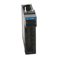
1756-OW16I
Allen-Bradley 1756-OW16I Manuals
Manuals and User Guides for Allen-Bradley 1756-OW16I. We have
1
Allen-Bradley 1756-OW16I manual available for free PDF download: User Manual
Allen-Bradley 1756-OW16I User Manual (258 pages)
ControlLogix Digital I/O Modules
Brand:
Allen-Bradley
| Category:
Control Unit
| Size: 2.9 MB
Table of Contents
Common Module Features Chapter
3
Diagnostic Module Features Chapter
4
Table of Contents
5
Studio 5000 Environment
11
Additional Resources
12
Chapter 1
13
Available Features
13
I/O Modules in the Controllogix System
14
Digital I/O Modules? I/O Modules in the Controllogix System
14
Module Identification and Status Information
17
Chapter 2
20
Ownership
20
Use Rsnetworx and Rslogix 5000 Software
20
Internal Module Operation
21
Input Modules
21
Output Modules
22
Connections
23
Direct Connections
24
Rack-Optimized Connections
24
Suggestions for Rack-Optimized Connections
26
Input Module Operation
26
Input Modules in a Local Chassis
27
Rpi
27
Cos
27
Trigger Event Tasks
28
Input Modules in a Remote Chassis
28
Remote Input Modules Connected Via the Controlnet Network
29
Remote Input Modules Connected Via the Ethernet/Ip Network
30
Output Module Operation
31
Output Modules in a Local Chassis
31
Output Modules in a Remote Chassis
32
Remote Output Modules Connected Via the Controlnet Network
32
Remote Output Modules Connected Via the Ethernet/Ip Network
33
Listen-Only Mode
34
Multiple Owner-Controllers of Input Modules
34
Configuration Changes in an Input Module with Multiple Owners
35
Input Module Compatibility
37
Chapter 3
38
Output Module Compatibility
38
Common Features
39
Removal and Insertion under Power
39
Module Fault Reporting
39
Software Configurable
40
Electronic Keying
40
Module Inhibiting
46
Use the System Clock to Timestamp Inputs and Schedule Outputs
47
Producer/Consumer Communication
50
Status Indicator Information
50
Common Features Specific to Input Modules
50
Data Transfer on Either Cyclic Time or Change of State
51
Set RPI
51
Enable Change of State
52
Software Configurable Filter Times
53
Isolated and Nonisolated Varieties of Input Modules
53
Multiple Input Point Densities
54
Common Features Specific to Output Modules
54
Configurable Point-Level Output States
55
Output Data Echo
56
Isolated and Nonisolated Varieties of Output Modules
56
Multiple Output Point Densities
57
Electronic Fusing
57
Field Power Loss Detection
60
Diagnostic Latch of Information
61
Time-Scheduled Output Control
63
Fault and Status Reporting between Input Modules and Controllers
64
Fault and Status Reporting between Output Modules and Controllers
65
Chapter 4
67
Diagnostic Input Module Compatibility
67
Diagnostic Output Module Compatibility
68
Diagnostic Features
68
Diagnostic Latch of Information
68
Diagnostic Timestamp
69
8-Point AC/16-Point DC
70
Point-Level Fault Reporting
70
Features Specific to Diagnostic Input Modules
71
Diagnostic Change of State for Input Modules
71
Open Wire Detection
73
Field Power Loss Detection
74
Features Specific to Diagnostic Output Modules
75
Field Wiring Options
75
No Load Detection
75
Field-Side Output Verification
76
Pulse Test
78
Diagnostic Change of State for Output Modules
79
Fault and Status Reporting between Input Modules and Controllers
79
Fault and Status Reporting between Output Modules and Controllers
81
Rockwell Automation Publication 1756-UM058G-EN-P - November
82
Diagnostic Module Features
67
Chapter 5
83
Fast Input Module Compatibility
83
Fast Output Module Compatibility
84
Fast Features
84
Response Time
85
Features Specific to Fast Input Modules
85
Pulse Capture
86
Per Point Timestamping and Change of State
87
Software Configurable Filter Times
90
Dedicated Connection for Event Tasks
93
Features Specific to Fast Output Modules
95
Programmable Fault State Delays
95
Pulse Width Modulation
97
Fault and Status Reporting between Input Modules and Controllers
106
Fault and Status Reporting between Output Modules and Controllers
107
Install the Module
111
Chapter 6
113
Key the Removable Terminal Block
113
Connect the Wires
114
RTB Types
116
RTB Wiring Recommendations
118
Assemble the Removable Terminal Block and Housing
119
Choose Extended-Depth Housing
120
Cabinet Size Considerations with Extended-Depth Housing
121
Install the Removable Terminal Block
122
Remove the Removable Terminal Block
123
Remove the Module from the Chassis
125
Configuration Process Overview
128
Chapter 7 Create a New Module
129
Communication or Connection Formats
131
Edit the Configuration
134
Connection Properties
135
View and Change Module Tags
136
1756-Ia8D
139
1756-Ia16
139
Chapter 8 Wiring Diagrams 1756-IA8D
139
1756-Ia16I
140
1756-Ia32
141
1756-Ib16
142
1756-Ib16D
143
1756-Ib16I
144
1756-Ib16If
145
1756-Ib32
146
1756-Ic16
147
1756-Ig16
148
1756-Ih16I
149
1756-Im16I
150
1756-In16
150
1756-Iv16
151
1756-Iv32
152
1756-Oa8
153
1756-Oa8D
154
1756-Oa8E
155
1756-Oa16
156
1756-Oa16I
157
1756-Ob8
158
1756-Ob8Ei
159
1756-Ob8I
160
1756-Ob16D
161
1756-Ob16E
162
1756-Ob16I
163
1756-Ob16Ief
164
1756-Ob16Iefs
165
1756-Ob16Is
166
1756-Ob32
167
1756-Oc8
168
1756-Og16
169
1756-Oh8I
170
1756-On8
171
1756-Ov16E
172
1756-Ov32E
173
1756-Ow16I
174
1756-Ox8I
175
Appendix A
177
Status Indicators for Input Modules
177
Status Indicators for Output Modules
178
Use Rslogix 5000 Software for Troubleshooting
180
Fault Type Determination
181
Troubleshoot Your Module
177
Appendix B
183
Standard and Diagnostic Input Module Tags
183
Standard and Diagnostic Output Module Tags
186
Fast Input Module Tags
189
Fast Output Module Tags
194
1756-OB16IEF Module
194
1756-OB16IEFS Module
202
Array Data Structures
211
Rockwell Automation Publication 1756-UM058G-EN-P - November
212
Using Message Instructions
213
Tag Definitions
183
Appendix C
214
Processing Real-Time Control and Module Services
214
One Service Performed Per Instruction
214
Create a New Tag
214
Enter Message Configuration
217
Configuration Tab
218
Communication Tab
221
Use Timestamped Inputs and Scheduled Outputs for Standard and Diagnostic I/O Modules
222
Use Timestamped Inputs and Scheduled Outputs
222
For Fast I/O Modules
224
Reset a Fuse, Perform Pulse Test and Reset Latched Diagnostics
227
Perform a WHO to Retrieve Module Identification and Status
228
Review of Tags in Ladder Logic
231
Appendix D
234
Determine the Maximum Number of Motor Starters
236
If Using a Compatible or Disabled Keying I/O Configuration
238
Appendix E if Using an Exact Match Keying Configuration
238
Cable Overview
239
Appendix G
249
Appendix H
249
1756-UM058F-EN-P, April 2012
249
1756-UM058E-EN-P, August 2010
250
Advertisement
Advertisement
Related Products
Allen-Bradley ControlLogix 1756-OA8
Allen-Bradley ControlLogix 1756-OA8D
Allen-Bradley 1756-OA8E
Allen-Bradley ControlLogix 1756-OA16
Allen-Bradley ControlLogix 1756-OA16I
Allen-Bradley 1756-OB8I
Allen-Bradley 1756-OX81
Allen-Bradley ControlLogix 1756-OF4
Allen-Bradley ControlLogix 1756-OF6VI
Allen-Bradley ControlLogix 1756-OX8I
Allen-Bradley Categories
Control Unit
Controller
I/O Systems
Switch
Power Supply
More Allen-Bradley Manuals
Login
Sign In
OR
Sign in with Facebook
Sign in with Google
Upload manual
Upload from disk
Upload from URL