Allen-Bradley 1756-IA8D User Manual
Controllogix digital i/o modules
Hide thumbs
Also See for 1756-IA8D:
- Installation instructions manual (16 pages) ,
- Installation instructions manual (16 pages)
Table of Contents
Advertisement
User Manual
ControlLogix Digital I/O Modules
Catalog Numbers 1756-IA8D, 1756-IA16, 1756-IA16I, 1756-IA32, 1756-IB16, 1756-IB16D, 1756-IB16I, 1756-IB16IF, 1756-IB32,
1756-IC16, 1756-IG16, 1756-IH16I, 1756-IM16I, 1756-IN16, 1756-IV16, 1756-IV32, 1756-OA8, 1756-OA8D, 1756-OA8E,
1756-OA16, 1756-OA16I, 1756-OB8, 1756-OB8EI, 1756-OB8I, 1756-OB16D, 1756-OB16E, 1756-OB16I, 1756-OB16IEF,
1756-OB16IEFS, 1756-OB16IS, 1756-OB32, 1756-OC8, 1756-OG16, 1756-OH8I, 1756-ON8, 1756-OV16E, 1756-OV32E,
1756-OW16I, 1756-OX81
Advertisement
Table of Contents

Related Manuals for Allen-Bradley 1756-IA8D


Summary of Contents for Allen-Bradley 1756-IA8D
- Page 1 User Manual ControlLogix Digital I/O Modules Catalog Numbers 1756-IA8D, 1756-IA16, 1756-IA16I, 1756-IA32, 1756-IB16, 1756-IB16D, 1756-IB16I, 1756-IB16IF, 1756-IB32, 1756-IC16, 1756-IG16, 1756-IH16I, 1756-IM16I, 1756-IN16, 1756-IV16, 1756-IV32, 1756-OA8, 1756-OA8D, 1756-OA8E, 1756-OA16, 1756-OA16I, 1756-OB8, 1756-OB8EI, 1756-OB8I, 1756-OB16D, 1756-OB16E, 1756-OB16I, 1756-OB16IEF, 1756-OB16IEFS, 1756-OB16IS, 1756-OB32, 1756-OC8, 1756-OG16, 1756-OH8I, 1756-ON8, 1756-OV16E, 1756-OV32E,...
- Page 2 IMPORTANT Identifies information that is critical for successful application and understanding of the product. Allen-Bradley, ControlLogix, ControlLogix-XT, DH+, Data Highway Plus, Integrated Architecture, Rockwell Software, Rockwell Automation, RSLogix, RSNetWorx, and TechConnect are trademarks of Rockwell Automation, Inc. Trademarks not belonging to Rockwell Automation are property of their respective companies.
-
Page 3: Common Module Features Chapter
Summary of Changes This manual contains new and updated information. Changes throughout this revision are marked by change bars, as shown to the right of this paragraph. Topic Page Studio 5000™ Logix Designer application is the rebranding of RSLogix™ 5000 software Added the 1756-OB16IEFS module to the list of I/O modules Added content to describe when output data is sent to the 1756-OB16IEFS module in motion applications... -
Page 4: Diagnostic Module Features Chapter
Summary of Changes Notes: Rockwell Automation Publication 1756-UM058G-EN-P - November 2012... -
Page 5: Table Of Contents
Table of Contents Preface Studio 5000 Environment ........11 Additional Resources . - Page 6 Table of Contents Use the System Clock to Timestamp Inputs and Schedule Outputs . 47 Producer/Consumer Communication......50 Status Indicator Information .
- Page 7 1756-IA8D ........
- Page 8 Table of Contents 1756-IB32 ..........146 1756-IC16 .
- Page 9 Table of Contents Appendix C Use Ladder Logic To Perform Using Message Instructions ........213 Processing Real-time Control and Module Services .
- Page 10 Table of Contents Notes: Rockwell Automation Publication 1756-UM058G-EN-P - November 2012...
-
Page 11: Studio 5000 Environment
Preface This manual describes how to install, configure, and troubleshoot your ControlLogix® digital I/O modules. There is also a complete listing of digital input and output modules, including specifications and wiring diagrams. You must be able to program and operate a ControlLogix controller to efficiently use your digital I/O module. -
Page 12: Additional Resources
Provides declarations of conformity, certificates, and other certification details. You can view or download publications at http://www.rockwellautomation.com/literature/. To order paper copies of technical documentation, contact your local Allen-Bradley distributor or Rockwell Automation sales representative. Rockwell Automation Publication 1756-UM058G-EN-P - November 2012... -
Page 13: Available Features
Chapter What Are ControlLogix Digital I/O Modules? Topic Page Available Features I/O Modules in the ControlLogix System Module Identification and Status Information ControlLogix® digital I/O modules are input and output modules that provide On/Off detection and actuation. By using the producer/consumer network model, digital I/O modules can produce information when needed while providing additional system functions. -
Page 14: I/O Modules In The Controllogix System
RTBs and page 239 for IFMs. Table 1 - ControlLogix Digital I/O Modules Cat. No. Description Page 1756-IA8D 79…132V AC 8-point diagnostic input module 1756-IA16 74…132V AC 16-point input module 1756-IA16I 79…132V AC 16-point isolated input module 1756-IA32 74…132V AC 32-point input module 1756-IB16 10…31.2V DC 16-point input module... - Page 15 What Are ControlLogix Digital I/O Modules? Chapter 1 Table 1 - ControlLogix Digital I/O Modules (continued) Cat. No. Description Page 1756-OB16E 10…31.2V DC 16-point electronically-fused output module 1756-OB16I 10…30V DC 16-point isolated output module 1756-OB16IEF 10…30V DC,16-point, isolated, fast peer control output module 1756-OB16IEFS 10…30V DC, 16-point, isolated, fast, scheduled per point output module 1756-OB16IS...
- Page 16 Chapter 1 What Are ControlLogix Digital I/O Modules? Figure 1 - Parts Illustration DC OUTPUT 3 4 5 6 7 Removable Terminal Block 40200-M Item Description Backplane Connector—Interface for the ControlLogix system that connects the module to the backplane. Top and bottom guides—Guides provide assistance in seating the RTB or IFM onto the module. Status indicators—Indicators display the status of communication, module health, and input/output devices.
-
Page 17: Module Identification And Status Information
• Minor recoverable fault • Minor unrecoverable fault • Major recoverable fault • Major unrecoverable fault Vendor Module’s manufacturer vendor, such as Allen-Bradley Serial number Module’s serial number Length of ASCII text string Number of characters in module’s text string ASCII text string Module’s ASCII text string description... - Page 18 Chapter 1 What Are ControlLogix Digital I/O Modules? Notes: Rockwell Automation Publication 1756-UM058G-EN-P - November 2012...
- Page 19 Chapter Digital I/O Operation in the ControlLogix System Topic Page Ownership Use RSNetWorx and RSLogix 5000 Software Internal Module Operation Connections Input Module Operation Input Modules in a Local Chassis Input Modules in a Remote Chassis Output Module Operation Output Modules in a Local Chassis Output Modules in a Remote Chassis Listen-only Mode Multiple Owner-Controllers of Input Modules...
-
Page 20: Ownership
Chapter 2 Digital I/O Operation in the ControlLogix System Ownership I/O modules in a ControlLogix system can be owned by an RSLogix™ 5000 controller. An owner-controller fulfills these functions: • Stores configuration data for every module that it owns • Sends I/O modules configuration data to define module behavior and begin module operation with the control system •... -
Page 21: Internal Module Operation
Digital I/O Operation in the ControlLogix System Chapter 2 Refer to the following general steps when configuring I/O modules. 1. Configure all I/O modules for a given controller by using RSLogix 5000 software and download that information to the controller. 2. -
Page 22: Output Modules
Chapter 2 Digital I/O Operation in the ControlLogix System The table defines some of the delay factors that affect the signal propagation on an I/O module. Delay Description Hardware How the module is configured and the variance between the type of modules affects how the signal is processed. -
Page 23: Connections
Digital I/O Operation in the ControlLogix System Chapter 2 The table defines some of the delay factors that affect the signal propagation on an I/O module. Delay Description Hardware How the module is configured and the variance between the type of modules affects how the signal is processed. -
Page 24: Direct Connections
Chapter 2 Digital I/O Operation in the ControlLogix System Direct Connections A direct connection is a real-time data transfer link between the controller and the device that occupies the slot that the configuration data references. When module configuration data is downloaded to an owner-controller, the controller attempts to establish a direct connection to each of the modules referenced by the data. - Page 25 Digital I/O Operation in the ControlLogix System Chapter 2 Because rack-optimized connections are applicable only in applications that IMPORTANT use a remote chassis, you must configure the communication format , as described in Chapter 7, for both the remote I/O module and the remote 1756-CNB module or EtherNet/IP module.
-
Page 26: Suggestions For Rack-Optimized Connections
Chapter 2 Digital I/O Operation in the ControlLogix System Suggestions for Rack-optimized Connections We recommend that you use a rack-optimized connection for these applications: • Standard digital I/O modules • Non-fused digital output modules • Owner-controllers running low on connections Rack-optimized connections are available only to digital I/O modules. -
Page 27: Input Modules In A Local Chassis
Digital I/O Operation in the ControlLogix System Chapter 2 Input Modules in a When a module resides in the same chassis as the owner-controller, the following two configuration parameters affect how and when an input module multicasts Local Chassis data: •... -
Page 28: Trigger Event Tasks
Chapter 2 Digital I/O Operation in the ControlLogix System Because the RPI and COS functions are asynchronous to the program scan, it is possible for an input to change state during program scan execution. The point must be buffered to prevent this from occurring. To buffer the point, you can copy the input data from your input tags to another structure and use the data from there. -
Page 29: Remote Input Modules Connected Via The Controlnet Network
Digital I/O Operation in the ControlLogix System Chapter 2 Remote Input Modules Connected via the ControlNet Network When an RPI value is specified for an input module in a remote chassis connected by a scheduled ControlNet network, in addition to instructing the module to multicast data within its own chassis, the RPI also reserves a spot in the stream of data flowing across the ControlNet network. -
Page 30: Remote Input Modules Connected Via The Ethernet/Ip Network
Chapter 2 Digital I/O Operation in the ControlLogix System Worst Case RPI Multicast Scenario In the worst case scenario, the module performs an RPI multicast just after the reserved network slot has passed. In this case, the owner-controller will not receive data until the next available network slot. -
Page 31: Output Module Operation
Digital I/O Operation in the ControlLogix System Chapter 2 Output Module Operation An owner-controller sends output data to an output module when either one of two things occur: • At the end of every one of its tasks (local chassis only) •... -
Page 32: Output Modules In A Remote Chassis
Chapter 2 Digital I/O Operation in the ControlLogix System Output Modules in a If an output module physically resides in a chassis other than that of the owner-controller, the owner-controller normally sends data to the output module Remote Chassis at the RPI rate specified. Updates are not performed at the end of the controller’s tasks. -
Page 33: Remote Output Modules Connected Via The Ethernet/Ip Network
Digital I/O Operation in the ControlLogix System Chapter 2 Worst Case RPI Multicast Scenario In the worst case scenario, the owner-controller sends the output data just after the reserved network slot has passed. In this case, the output module does not receive data until the next available network slot. -
Page 34: Listen-Only Mode
Chapter 2 Digital I/O Operation in the ControlLogix System Listen-only Mode Any controller in the system can listen to the data from any I/O module, such as input data, echoed output data, or echoed diagnostic information. Even if a controller does not own a module, or hold the module’s configuration data, the controller can still listen to the module. -
Page 35: Configuration Changes In An Input Module With Multiple Owners
Digital I/O Operation in the ControlLogix System Chapter 2 As soon as a controller receives its user program, it will try to establish a connection with the input module. A connection is established with the controller whose configuration data arrives first. When the second controller’s configuration data arrives, the module compares it to its current configuration data, which was received and accepted from the first controller. - Page 36 Chapter 2 Digital I/O Operation in the ControlLogix System To prevent other owner-controllers from receiving potentially erroneous data, use these steps when changing a module’s configuration in a multiple owner scenario while online. 1. For each owner-controller, inhibit the connection to the module either in the software on the Connection tab or the message dialog box warning you of the multiple owner condition.
-
Page 37: Input Module Compatibility
Chapter Common Module Features Topic Page Input Module Compatibility Output Module Compatibility Common Features Common Features Specific to Input Modules Common Features Specific to Output Modules Fault and Status Reporting between Input Modules and Controllers Fault and Status Reporting between Output Modules and Controllers Input Module Compatibility ControlLogix digital input modules interface to sensing devices and detect whether they are On or Off. -
Page 38: Output Module Compatibility
Chapter 3 Common Module Features Output Module Compatibility ControlLogix output modules can be used to drive a variety of output devices. Typical output devices compatible with ControlLogix outputs include these items: • Motor starters • Solenoids • Indicators Follow these guidelines when designing a system: •... -
Page 39: Common Features
Common Module Features Chapter 3 Common Features The table below lists features common to all ControlLogix digital I/O modules. Topic Page Removal and Insertion Under Power Module Fault Reporting Software Configurable Electronic Keying Module Inhibiting Use the System Clock to Timestamp Inputs and Schedule Outputs Producer/Consumer Communication Status Indicator Information Removal and Insertion Under Power... -
Page 40: Software Configurable
Chapter 3 Common Module Features Software Configurable RSLogix 5000 software provides an interface to configure each module. All module features are enabled or disabled through the I/O configuration within the software. You can also use the software to retrieve the following information from any module in the system: •... - Page 41 Attribute Description Vendor The manufacturer of the module, for example, Allen-Bradley. Product Type The general type of the module, for example, communication adapter, AC drive, or digital I/O. Product Code The specific type of module, generally represented by its catalog number, such as 1756-IB16I.
- Page 42 3.1. The physical module is a 1756-IB16D module with module revision 3.2. In this case, communication is prevented because the Minor Revision of the module does not match precisely. Module Configuration Vendor = Allen-Bradley Product Type = Digital Input Module Catalog Number = 1756-IB16D Major Revision = 3...
- Page 43 3.3. Module Configuration Vendor = Allen-Bradley Product Type = Digital Input Module Catalog Number = 1756-IB16D Major Revision = 3...
- Page 44 Module Configuration Vendor = Allen-Bradley Product Type = Digital Input Module Catalog Number = 1756-IB16D Major Revision = 2...
- Page 45 1756-IF16 analog input module. In this case, communication is prevented because the analog module rejects the data formats that the digital module configuration requests. Module Configuration Vendor = Allen-Bradley Product Type = Digital Input Module Catalog Number = 1756-IA16 Major Revision = 3...
-
Page 46: Module Inhibiting
Chapter 3 Common Module Features Changing electronic keying selections online may cause the I/O IMPORTANT communication connection to the module to be disrupted and may result in a loss of data. Module Inhibiting Module inhibiting lets you indefinitely suspend a connection between an owner-controller and a digital I/O module without having to remove the module from the configuration. -
Page 47: Use The System Clock To Timestamp Inputs And Schedule Outputs
Common Module Features Chapter 3 Use the System Clock to Timestamp Inputs and Schedule Outputs This section describes how to use CST timestamps in standard and diagnostic I/O modules and the CIP Sync timestamps in fast I/O modules. Use Coordinated System Time with Standard and Diagnostic I/O Modules Time masters generate a 64-bit coordinated system time (CST) for their respective chassis. - Page 48 Chapter 3 Common Module Features Use CIP Sync Time with Fast I/O Modules The 1756-IB16IF, 1756-OB16IEF, and 1756-OB16IEFS modules use CIP Sync for both timestamps and scheduling. CIP Sync is a CIP implementation of the IEEE 1588 PTP (Precision Time Protocol).
- Page 49 Common Module Features Chapter 3 Mixing CST and CIP Sync Modules in a ControlLogix System CST is automatically enabled for each chassis that has been configured to use CIP Sync. Therefore, it is possible to include modules that use CST for their time base into systems that have been configured to use CIP Sync.
-
Page 50: Producer/Consumer Communication
Chapter 3 Common Module Features Producer/Consumer Communication By using Producer/Consumer communication, ControlLogix I/O modules can produce data without first being polled by a controller. The modules produce the data and any other owner-controller device can decide to consume it. For example, an input module produces data and any number of processors can consume the data at the same time. -
Page 51: Data Transfer On Either Cyclic Time Or Change Of State
Common Module Features Chapter 3 Data Transfer on Either Cyclic Time or Change of State Digital input modules always send data at the RPI, but they send data at a change of state only if the COS feature is enabled. COS is more efficient than RPI because it multicasts data only when a change occurs. -
Page 52: Enable Change Of State
Chapter 3 Common Module Features Enable Change of State The Point column on the left side of the Configuration tab lets you set whether a COS occurs when a field device transitions from Off to On or On to Off. Follow these steps to enable or disable COS. -
Page 53: Software Configurable Filter Times
Common Module Features Chapter 3 Software Configurable Filter Times On to Off and Off to On filter times can be adjusted through RSLogix 5000 software for all ControlLogix input modules. These filters improve noise immunity within a signal. A larger filter value affects the length of delay times for signals from these modules. -
Page 54: Multiple Input Point Densities
Chapter 3 Common Module Features Multiple Input Point Densities ControlLogix input modules use either 8-, 16-, or 32-point densities for greater flexibility in your application. A point is the termination where a wire attaches to the input module from a field device. The module receives information from the device to this designated point, thus signaling when activity occurs. -
Page 55: Configurable Point-Level Output States
Common Module Features Chapter 3 Configurable Point-level Output States Individual outputs can be configured to unique output states if the module goes into Program mode or Fault mode. Whenever you inhibit an output module, it enters Program mode, and all IMPORTANT outputs change to the state configured for Program mode. -
Page 56: Output Data Echo
Chapter 3 Common Module Features Output Data Echo During normal operation, when a controller sends out an output command to the ControlLogix system, the output module that is targeted for that command returns the commanded state of the output to the system. This process verifies that the module has received the command and will try to execute it. -
Page 57: Multiple Output Point Densities
Common Module Features Chapter 3 Multiple Output Point Densities ControlLogix output modules use either 8-, 16-, or 32-point densities for greater flexibility in your application. A point is the termination where a wire attaches to the I/O module from a device. The I/O gets information from the device to this designated point, thus signaling when activity occurs. - Page 58 Chapter 3 Common Module Features Table 3 - Recommended Fuses (continued) Circuit Type Cat. No. Fusing on the module Recommended Fuse Fuse Supplier 1756-OB8 None—Fused IFM can be used to protect outputs 5x20mm SOC p/n 4A Quick acting MQ2-4A 1756-OB81 (2) (3) (6) 1756-OB8EI Yes—Fused on a per point basis...
- Page 59 Common Module Features Chapter 3 You can reset an electronic fuse through RSLogix 5000 software during online monitoring or through program logic running on a controller. If your module uses point-level fusing, you can reset a fuse with a CIP Generic Message instruction, as described on page 227.
-
Page 60: Field Power Loss Detection
Chapter 3 Common Module Features Field Power Loss Detection For the standard digital output modules, the Field Power Loss detection feature is found on the 1756-OA8E module only. When field power to the module is lost, or zero cross cannot be detected, a point-level fault is sent to the controller to identify the exact point faulted. -
Page 61: Diagnostic Latch Of Information
Common Module Features Chapter 3 Diagnostic Latch of Information The diagnostic latch feature is available for the 1756-OA8E modules only. Diagnostic latching allows this module to latch a fault in the set position once it has been triggered, even if the error condition causing the fault to occur disappears. - Page 62 Chapter 3 Common Module Features Latched diagnostic features can be cleared by using these methods: • Reset Diagnostic Latch service • Software reset during online monitoring • Cycling power to the module’s Follow these steps to a reset a latched fault through RSLogix 5000 software during online monitoring.
-
Page 63: Time-Scheduled Output Control
Common Module Features Chapter 3 Time-scheduled Output Control Time-scheduled output control is available for these modules: • 1756-OB16IS—Provides time-scheduled output control in CST time for outputs 0…7. Allows for schedules with a minimum interval of 100 μs. • 1756-OB16IEFS—Provides time-scheduled output control in CIP Sync time for outputs 0…15. -
Page 64: Fault And Status Reporting Between Input Modules And Controllers
Chapter 3 Common Module Features Use the Module Properties dialog box in RSLogix 5000 software to determine if the module has been synchronized with the owner-controller and whether the controller is synchronized with the CST. For more information on synchronizing owner-controllers and modules with the CST, see the ControlLogix System User Manual, publication 1756-UM001. -
Page 65: Fault And Status Reporting Between Output Modules And Controllers
Common Module Features Chapter 3 Fault and Status Reporting ControlLogix digital output modules multicast fault and status data to any owner-controller or listening controller. Like input modules, output modules between Output Modules maintain a module-fault word, the highest level of fault reporting. However, and Controllers some output modules use additional words to indicate fault conditions. - Page 66 Chapter 3 Common Module Features The following illustration offers an overview of the fault reporting process on ControlLogix digital output modules. Bit 31 Bit 0 Module-fault Word All modules A communications fault sets all bits in the module-fault word. A fuse blown or field power loss condition sets the appropriate bits in the module-fault word.
-
Page 67: Diagnostic Module Features
The table lists the available diagnostic digital I/O modules. Cat. No. Description 1756-IA8D 79…132V AC 8-point diagnostic input module 1756-IB16D 10…30V DC diagnostic input module 1756-OA8D 74…132V AC 8-point diagnostic output module... -
Page 68: Diagnostic Output Module Compatibility
Chapter 4 Diagnostic Module Features Diagnostic Output ControlLogix diagnostic output modules are capable of directly driving the ControlLogix diagnostic digital inputs. When diagnostics are used, a shunt Module Compatibility resistor is required for leakage current. For more information on the compatibility of motor starters with ControlLogix output modules, see Appendix Diagnostic Features... -
Page 69: Diagnostic Timestamp
Diagnostic Module Features Chapter 4 2. Do one of the following in the Enable Diag. Latching column: • To enable diagnostic latching for a specific point, check the corresponding checkbox. • To disable diagnostic latching for a specific point, clear the corresponding checkbox. -
Page 70: 8-Point Ac/16-Point Dc
These conditions can set a fault bit for an input point: These conditions can set a fault bit for an output point: • Open wire • Fuse blown • Field power loss (1756-IA8D only) • No load • Output verify • Field power loss (1756-IA8D only) Using these bits in tandem with data echo and manually performing a pulse test can help to further isolate the fault. -
Page 71: Features Specific To Diagnostic Input Modules
Diagnostic Module Features Chapter 4 The following table lists possible diagnostic faults on the 1756-OB16D module. Table 10 - 1756-OB16D Point-level Fault Scenarios Ladder commands output to be On Ladder commands output to be Off Possible cause of fault 1. Output Data Echo returns the state of the output as Off. 1. - Page 72 Chapter 4 Diagnostic Module Features Although the RPI occurs continuously, the COS feature lets you to decide whether changes in a module’s diagnostic detection should cause the module to send real-time data to the owner-controller. 1. On the Module Properties dialog box, click the Configuration tab. 2.
-
Page 73: Open Wire Detection
Diagnostic Module Features Chapter 4 Open Wire Detection Open Wire is used to verify the field wiring is connected to the module. The field device must provide a minimum leakage current to function properly. A leakage resistor must be placed across the contacts of an input device. The resulting current is then expected to exist when the input is open. -
Page 74: Field Power Loss Detection
For the standard digital output modules, the Field Power Loss detection feature is found on the 1756-IA8D module only. When field power to the module is lost, or zero cross cannot be detected, a point-level fault is sent to the controller to identify the exact point faulted. -
Page 75: Features Specific To Diagnostic Output Modules
Diagnostic Module Features Chapter 4 Features Specific to The table below lists features specific to ControlLogix diagnostic digital output modules. Diagnostic Output Modules Topic Page Field Wiring Options No Load Detection Field-side Output Verification Pulse Test Diagnostic Change of State for Output Modules Field Wiring Options As with diagnostic input modules, ControlLogix diagnostic output modules provide isolated or nonisolated wiring options. -
Page 76: Field-Side Output Verification
Chapter 4 Diagnostic Module Features Diagnostic output modules list a minimum load current specification (1756-OA8D = 10 mA & 1756-OB16D = 3 mA). In the On state, the module must be connected to a load that will draw a minimum current equal to these values. - Page 77 Diagnostic Module Features Chapter 4 This feature has a corresponding tag that can be examined in the user program in the event of a fault. For more information on these tags, see Appendix If an output cannot be verified, a point-level fault is sent to the controller. Follow these steps to enable the field-side output verification.
-
Page 78: Pulse Test
Chapter 4 Diagnostic Module Features Pulse Test Pulse test is a feature found on diagnostic output modules that can verify output- circuit functionality without actually changing the state of the output load device. A short pulse is sent to the targeted output circuit. The circuit should respond as it would if a real change-of-state command was issued, but the load device does not transition. -
Page 79: Diagnostic Change Of State For Output Modules
Provides fault summary reporting. Available on all digital input modules. Field Power Loss FieldPwrLoss Indicates loss of field power to a group on the module. Available on the 1756-IA8D only. For more information, see Field Power Loss Detection on page Open Wire OpenWire Indicates the loss of a wire from a point on the module. - Page 80 -fault word. Group 1 Group 0 Field Power Loss Word 1756-IA8D only A loss of field power sets the bit for that group in the field-power loss word and also sets the appropriate bit in the module-fault word. Open Wire Word An open wire condition on any point sets the bit for that point in the open wire word and also sets the appropriate bit in the module-fault word.
-
Page 81: Fault And Status Reporting Between Output Modules And Controllers
Diagnostic Module Features Chapter 4 Fault and Status Reporting ControlLogix diagnostic digital output modules multicast fault and status data to any owner-controller or listening controller. Like input modules, output modules between Output Modules maintain a module-fault word, the highest level of fault reporting. However, and Controllers some output modules use additional words to indicate fault conditions. -
Page 82: Rockwell Automation Publication 1756-Um058G-En-P - November
Chapter 4 Diagnostic Module Features The following illustration provides an overview of the fault reporting process for digital output modules. Bit 31 Bit 0 Module-fault Word A communications fault sets all bits in the module-fault word. A fuse blown, field-power loss, no load or output verify condition sets the appropriate bit in the module-fault word. -
Page 83: Fast Input Module Compatibility
Chapter Fast Module Features Topic Page Fast Input Module Compatibility Fast Output Module Compatibility Fast Features Features Specific to Fast Input Modules Features Specific to Fast Output Modules Fault and Status Reporting between Input Modules and Controllers Fault and Status Reporting between Output Modules and Controllers Fast digital I/O modules provide quick response time for high-speed control applications. -
Page 84: Fast Output Module Compatibility
Chapter 5 Fast Module Features Fast Output Module ControlLogix fast output modules can be used to drive a variety of output devices. Typical output devices compatible with ControlLogix outputs include Compatibility these items: • Solenoids • Indicators Follow these guidelines when designing a system: •... -
Page 85: Response Time
Fast Module Features Chapter 5 Response Time The tables below indicate the screw-to-backplane response time of fast input and fast output modules. Table 16 - Input Response Time Delay Response Time Total On/Off delay (screw to backplane) 14 μs nom/23 μs max + user-configurable filter time Hardware delay <... -
Page 86: Pulse Capture
Chapter 5 Fast Module Features Pulse Capture The 1756-IB16IF fast input module can be used to detect or latch short duration pulses. The module can detect incoming pulses with a duration as short as 10 μs if the frequency is under 4 kHz (period of 250 μs). When the module detects a short duration pulse at an input point, it sets the corresponding bit for the Pt[x].NewDataOffOn or Pt[x].NewDataOnOff input tag. -
Page 87: Per Point Timestamping And Change Of State
Fast Module Features Chapter 5 Per Point Timestamping and Change of State With per point timestamping, each input point on the module records timestamps in CIP Sync format at these speeds: • ± 4 μs for inputs < 4 kHz •... - Page 88 Chapter 5 Fast Module Features Follow these steps to configure per point timestamping and enable COS. 1. On the New Module dialog box, click Change to display the Module Definition dialog box. Opens the Module Definition dialog box. 2. Use the table below to choose a connection format and input data type from the Connection and Input Data pull-down menus.
- Page 89 Fast Module Features Chapter 5 3. On the New Module or Module Properties dialog box, click the Configuration tab. Timestamp fields only appear on the Configuration tab when you choose Timestamp Data from the Input Data pull-down menu on the Module Definition dialog box.
-
Page 90: Software Configurable Filter Times
Chapter 5 Fast Module Features Software Configurable Filter Times To account for hard contact bounce, you can configure Off to On and On to Off input filter times of 0…30, 000 μs in RSLogix 5000 software. These filters define how long an input transition must remain in the new state before the module considers the transition valid. - Page 91 Fast Module Features Chapter 5 Figure 9 - Valid Transition with No Bounce Input remains On for at least 2 ms. The transition is considered valid, and the timestamp is sent to the controller. Input turns On, and a timestamp is recorded. Time in milliseconds Figure 10 - Transition Valid with Bounce Input turns On and remains On for at least 2 ms in the...
- Page 92 Chapter 5 Fast Module Features Follow these steps to configure input filter times. 1. On the Module Properties dialog box, click the Configuration tab. 2. In the Input Filter Time column, enter Off to On and On to Off input filter times from 0…30,000 μs and click OK.
-
Page 93: Dedicated Connection For Event Tasks
Fast Module Features Chapter 5 Dedicated Connection for Event Tasks The 1756-IB16IF input module can initiate an event task over a dedicated second connection in response to four user-defined input patterns. You can define these patterns in real time during a control process by using these output tags: •... - Page 94 Chapter 5 Fast Module Features In example pattern 4, the input module triggers the event task when input points 0…3 are in the On state, and input points 12…15 are in the Off state. Table 21 - Example Pattern 4 Output Tag Bit Position Event[x].Mask...
-
Page 95: Features Specific To Fast Output Modules
Fast Module Features Chapter 5 Features Specific to The table below lists features specific to ControlLogix fast digital output modules. Fast Output Modules Topic Page Programmable Fault State Delays Pulse Width Modulation Peer I/O Control (1756-OB16IEF only) See the Peer I/O Control Application Technique, publication 1756-AT016 In RSLogix 5000 software, version 18.02.00 and 19.01.00, output tag... - Page 96 Chapter 5 Fast Module Features For more information about defining a Fault mode state, refer to Configurable Point-level Output States on page Follow these steps to configure a fault state delay. 1. On the Module Properties dialog box, click the Output State tab. 2.
-
Page 97: Pulse Width Modulation
Fast Module Features Chapter 5 Pulse Width Modulation Pulse Width Modulation (PWM) provides precise, onboard control of an output’s pulse train with no program variability. To configure a PWM signal, you define two real-time values for the pulse train in the module’s output tags: •... - Page 98 Chapter 5 Fast Module Features Figure 13 compares two applications in which the output is instructed to turn On for 4.5 seconds: • In the application without PWM, a single pulse is generated. The pulse remains active for the same length of time the Data output tag is On (4.5 seconds).
- Page 99 Fast Module Features Chapter 5 The Program and Fault mode states configured for the module override the IMPORTANT PWM output state unless the point is configured to hold the last state while in Program or Fault mode. If a point is configured to hold the last state and the output is currently On, the output will continue to use PWM until the PWM cycle limit is reached, the module transitions out of Program or Fault mode, or a final fault state goes into effect.
- Page 100 Chapter 5 Fast Module Features If the output logic turns Off before the cycle limit is reached, you can configure the pulse cycles to continue until the cycle limit is reached by enabling the Execute All Cycles option. Figure 16 shows a cycle limit of 2 with the Execute All Cycles option enabled.
- Page 101 Fast Module Features Chapter 5 In this type of application, the Minimum On Time, Extend Cycle, and Stagger Output configuration options provide these benefits: • Minimum On Time and Extend Cycle—Ensures that output devices that require a minimum time to turn On or that cannot react to a short pulse cycle can react with any given PWM On time calculation rather than not turning On.
- Page 102 Chapter 5 Fast Module Features Figure 18 - Outputs with Staggering Output 1 Output 2 Output 3 Figure 19 - Outputs without Staggering Output 1 Output 2 Output 3 Rockwell Automation Publication 1756-UM058G-EN-P - November 2012...
- Page 103 Fast Module Features Chapter 5 PWM Configuration Follow these steps to configure PWM. 1. Use program logic or the RSLogix 5000 tag editor to define the Cycle time and On time for an output point via the PWMCycleTime and PWMOnTime output tags. For more information about module tags, refer to Appendix 2.
- Page 104 Chapter 5 Fast Module Features 4. In the Pulse Width Modulation area, complete the fields as described in the table below. Field Description 1756-OB16IEF Tag Name 1756-OB16IEFS Tag Name Enable Pulse Width Modulation Check the checkbox to enable PWM. If this checkbox is cleared, all other PWM C:Pt[x].PWMEnable C:PWM.Enable (PWM)
- Page 105 Fast Module Features Chapter 5 Field Description 1756-OB16IEF Tag Name 1756-OB16IEFS Tag Name Enable Cycle Limit Check the checkbox to allow only a fixed number of pulse cycles to occur. C:Pt[x].PWMCycleLimitEnable C:PWM.CycleLimitEnable Figure 15 on page By default, the Enable Cycle Limit checkbox is cleared, and pulse cycles continue to occur until the output turns Off.
-
Page 106: Fault And Status Reporting Between Input Modules And Controllers
Chapter 5 Fast Module Features Fault and Status Reporting ControlLogix fast input modules multicast fault and status data to any owner- controller or listening controller. All input modules maintain a Module Fault between Input Modules and word, the highest level of fault reporting. Modules configured to use the Data Controllers with Event connection format also maintain an Event Fault word to report on the status of an event connection. -
Page 107: Fault And Status Reporting Between Output Modules And Controllers
Fast Module Features Chapter 5 Fault and Status Reporting ControlLogix fast digital output modules multicast fault and status data to any owner-controller or listening controller. Like input modules, output modules between Output Modules maintain a Module Fault word, the highest level of fault reporting. However, and Controllers output modules use an additional word to indicate a fault condition. - Page 108 Chapter 5 Fast Module Features Notes: Rockwell Automation Publication 1756-UM058G-EN-P - November 2012...
- Page 109 Chapter Install ControlLogix I/O Modules Topic Page Install the Module Key the Removable Terminal Block Connect the Wires Assemble the Removable Terminal Block and Housing Choose Extended-depth Housing Install the Removable Terminal Block Remove the Removable Terminal Block Remove the Module from the Chassis ATTENTION: Environment and Enclosure This equipment is intended for use in a Pollution Degree 2 industrial environment, in overvoltage Category II applications (as defined in IEC 60664-1), at altitudes up to 2000 m (6562 ft) without derating.
- Page 110 Chapter 6 Install ControlLogix I/O Modules North American Hazardous Location Approval The following information applies when operating this equipment in Informations sur l’utilisation de cet équipement en environnements hazardous locations. dangereux. Products marked "CL I, DIV 2, GP A, B, C, D" are suitable for use in Class I Division 2 Groups Les produits marqués "CL I, DIV 2, GP A, B, C, D"...
-
Page 111: Install The Module
Install ControlLogix I/O Modules Chapter 6 Install the Module You can install or remove a ControlLogix I/O module while chassis power is applied. Removal and Insertion Under Power (RIUP) provides the flexibility to maintain modules without having to stop production. WARNING: When you insert or remove the module while backplane power is on, an electrical arc can occur. - Page 112 Chapter 6 Install ControlLogix I/O Modules Follow these steps to insert the module into the chassis. 1. Align the circuit board with the top and bottom chassis guides. Printed Circuit Board 20861-M 2. Slide the module into the chassis until the locking tabs click. 20862-M Installation of the module is now complete.
-
Page 113: Key The Removable Terminal Block
Install ControlLogix I/O Modules Chapter 6 Key the Removable Key the removable terminal block (RTB) to prevent inadvertently connecting the wrong wiring in the RTB to your module. Wedge- and U-shaped bands are Terminal Block manually inserted into the RTB and module. This process hinders a wired RTB from being accidentally inserted into a module that does not match the positioning of the respective tabs. -
Page 114: Connect The Wires
Chapter 6 Install ControlLogix I/O Modules 3. To key the RTB in positions that correspond to unkeyed module positions, insert the straight, wedge-shaped tab on the RTB with the rounded edge first. Module side of RTB 20851-M 4. Push the tab onto the RTB until it stops. 5. - Page 115 RTB type. The following table shows each module catalog number and the corresponding page with the wiring diagram. Cat. No. Page Cat. No. Page 1756-IA8D 1756-OA16I 1756-IA16 1756-OB8 1756-IA16I 1756-OB8EI 1756-IA32...
-
Page 116: Rtb Types
Chapter 6 Install ControlLogix I/O Modules RTB Types There are three types of RTBs: • Cage Clamp—catalog number 1756-TBCH • NEMA Clamp—catalog number 1756-TBNH • Spring Clamp—catalog number 1756-TBSH or TBS6H Each RTP comes with housing. Wire the RTB with a 3.2 mm (1/8 in.) maximum screwdriver before installing it onto the module. - Page 117 Install ControlLogix I/O Modules Chapter 6 NEMA Clamp Follow these steps to wire a NEMA clamp. 1. Strip 8 mm (5/16 in.) maximum length of wire. 2. Turn the terminal screw counterclockwise. 3. Insert the stripped end of the wire under the plate on the terminal. Strain Relief Area 40201-M 4.
-
Page 118: Rtb Wiring Recommendations
Chapter 6 Install ControlLogix I/O Modules Make sure the wire, and not the screwdriver, is inserted into the open terminal IMPORTANT to prevent damage to the module. The open section at the bottom of the RTB is called the strain relief area. The wiring from the connections can be grouped with a plastic tie. -
Page 119: Assemble The Removable Terminal Block And Housing
Install ControlLogix I/O Modules Chapter 6 Assemble the Removable Removable housing covers the wired RTB to protect wiring connections when the RTB is seated on the module. Parts of the catalog number 1756-TBCH RTB Terminal Block and Housing (example below) are identified in the table. 20858-M Item Description... -
Page 120: Choose Extended-Depth Housing
Chapter 6 Install ControlLogix I/O Modules Choose Extended-depth There are two housing options you must consider when wiring your ControlLogix digital I/O module: standard-depth or extended-depth. Housing When you order an RTB for your I/O module, you receive standard-depth housing. If your application uses heavy gauge wiring, you can order extended- depth housing. -
Page 121: Cabinet Size Considerations With Extended-Depth Housing
Install ControlLogix I/O Modules Chapter 6 Cabinet Size Considerations with Extended-depth Housing When you use extended-depth housing, catalog number 1756-TBE, the I/O module depth is increased. The diagram shows the difference in depth between an I/O module using standard-depth housing and one using extended-depth housing. -
Page 122: Install The Removable Terminal Block
Chapter 6 Install ControlLogix I/O Modules Install the Removable This section shows how to install the RTB onto the module to connect the wiring. Terminal Block WARNING: When you connect or disconnect the Removable Terminal Block (RTB) with field side power applied, an electrical arc can occur. This could cause an explosion in hazardous location installations. -
Page 123: Remove The Removable Terminal Block
Install ControlLogix I/O Modules Chapter 6 3. Slide the locking tab down to lock the RTB onto the module. 20854-M Remove the Removable If you need to remove the module from the chassis, you must first remove the RTB from the module. Terminal Block ATTENTION: Shock hazard exists. - Page 124 Chapter 6 Install ControlLogix I/O Modules Follow these steps to remove an RTB from the module. 1. Unlock the locking tab at the top of the module. 2. Open the RTB door by using the bottom tab. 3. Hold the spot marked PULL HERE and pull the RTB off the module. IMPORTANT Do not wrap your fingers around the entire door.
-
Page 125: Remove The Module From The Chassis
Install ControlLogix I/O Modules Chapter 6 Remove the Module Follow these steps to remove a module from its chassis. from the Chassis 1. Push in the top and bottom locking tabs. 20856-M 2. Pull module out of the chassis. 20857-M Rockwell Automation Publication 1756-UM058G-EN-P - November 2012... - Page 126 Chapter 6 Install ControlLogix I/O Modules Notes: Rockwell Automation Publication 1756-UM058G-EN-P - November 2012...
- Page 127 Chapter Configure ControlLogix Digital I/O Modules Topic Page Configuration Process Overview Create a New Module Edit the Configuration Connection Properties View and Change Module Tags You must configure your module upon installation. The module will not work until it has been configured. In most cases, you will use RSLogix 5000 software to complete the configuration.
-
Page 128: Configuration Process Overview
Chapter 7 Configure ControlLogix Digital I/O Modules Configuration Follow these steps to configure a ControlLogix digital I/O module with RSLogix 5000 software. Process Overview 1. Create a new module. 2. Accept or customize the default configuration for the module. 3. Edit the configuration as changes are needed. Figure 20 - Full Configuration Profile Diagram New Module 1. -
Page 129: Create A New Module
Configure ControlLogix Digital I/O Modules Chapter 7 Create a New Module Before creating a new module, make sure you complete these procedures in RSLogix 5000 software: • Create a controller project. • If you plan to add the I/O module to a remote chassis, add ControlNet or EtherNet/IP communication modules to both the local and remote chassis in the I/O Configuration tree. - Page 130 Chapter 7 Configure ControlLogix Digital I/O Modules 3. On the Select Major Revision dialog box, click OK to accept the default major revision. 4. On the New Module dialog box, complete the fields and click OK. • For information about choosing an electronic keying method, see page •...
-
Page 131: Communication Or Connection Formats
Configure ControlLogix Digital I/O Modules Chapter 7 Communication or Connection Formats The initial configuration of a module requires you to choose a communication or connection format. The term used depends on the AOP for your module. Earlier AOPs use communication formats, and later AOPs use connection formats. A communication or connection format determines the following: •... - Page 132 Listen Only—Rack Optimization Full Diagnostic Input Data Module returns input data, the value of the system clock from its 1756-IA8D, 1756-IB16D local chassis when the input data changes, and diagnostic data. Listen Only—Full Diagnostic Input Data This format has the same definition as Full diagnostic input data 1756-IA8D, 1756-IB16D except that it is a Listen-only connection.
- Page 133 Configure ControlLogix Digital I/O Modules Chapter 7 The tables below describe the communication and connection formats available for output modules. Table 28 - Output Module Communication Formats Communication Format Data Return Module Output Data The owner-controller sends the module only output data. 1756-OA8, 1756-OA16I, 1756-OB8, 1756-OB8I, 1756-OB16I, 1756-OB16IS Scheduled Output Data...
-
Page 134: Edit The Configuration
Chapter 7 Configure ControlLogix Digital I/O Modules Edit the Configuration After you add a module to the I/O configuration in RSLogix 5000 software, you can review and edit the configuration. You can also download the data to the controller while online. This is called dynamic reconfiguration. Follow these steps to edit a module’s configuration. -
Page 135: Connection Properties
Configure ControlLogix Digital I/O Modules Chapter 7 Connection Properties Connection properties define controller-to-module behavior. When defining connection properties, you can do the following: • Select a requested packet interval (RPI) to set a defined, maximum period of time when data is transferred to the owner-controller •... -
Page 136: View And Change Module Tags
Chapter 7 Configure ControlLogix Digital I/O Modules View and Change When you create a module, a set of tags is created by the ControlLogix system that can be viewed in the Tag Editor of RSLogix 5000 software. Each configured Module Tags feature on your module has a unique tag that can be used in the controller’s program logic. - Page 137 Chapter Wiring Diagrams Cat. No. Page Cat. No. Page 1756-IA8D 1756-OA16I 1756-IA16 1756-OB8 1756-IA16I 1756-OB8EI 1756-IA32 1756-OB8I 1756-IB16 1756-OB16D 1756-IB16D 1756-OB16E 1756-IB16I 1756-OB16I 1756-IB16IF 1756-OB16IEF 1756-IB32 1756-OB16IEFS 1756-IC16 1756-OB16IS 1756-IG16 1756-OB32 1756-IH16I 1756-OC8 1756-IM16I 1756-OG16 1756-IN16 1756-OH81 1756-IV16 1756-ON8 1756-IV32...
- Page 138 Chapter 8 Wiring Diagrams The 1756 digital I/O modules support these features. Table 30 - 1756 I/O Module Features Module Type Features 1756 digital AC input modules • Change of state: Software configurable • Timestamp of inputs: ±200 μs • Module keying: Electronic, software configurable •...
-
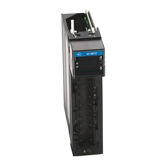
Page 139: 1756-Ia8D
Wiring Diagrams Chapter 8 1756-IA8D ControlLogix AC (79...132V) diagnostic input module 1756-IA8D Simplified Schematic Not Used L1-0 Loss of Field Power Daisy Chain to Input L2-0 IN-0 Other RTBs Display L2-0 IN-1 ControlLogix Backplane Group 0 Group L2-0 IN-2 47 kΩ, 1/2 W... -
Page 140: 1756-Ia16I
Chapter 8 Wiring Diagrams 1756-IA16I ControlLogix AC (79...132V) isolated input module 1756-IA16I Simplified Schematic Isolated Wiring L2-0 L2-0 IN-0 L1-0 IN-O L2-1 IN-1 L2-2 L2-2 IN-2 L1-2 L2-0 L2-3 IN-3 L2-4 L2-4 IN-4 L1-4 L2-5 IN-5 L2-6 IN-6 L2-7 IN-7 ControlLogix Display Jumper Bar... -
Page 141: 1756-Ia32
Wiring Diagrams Chapter 8 1756-IA32 ControlLogix AC (74...132V) input module Simplified Schematic 1756-IA32 IN-O IN-1 IN-0 IN-3 IN-2 L2-0 IN-4 IN-5 IN-6 IN-7 IN-8 IN-9 Daisy Chain IN-11 to Other RTBs IN-10 ControlLogix Display IN-13 IN-12 Backplane IN-15 IN-14 Interface L2-0 L2-0 IN-17... -
Page 142: 1756-Ib16
Chapter 8 Wiring Diagrams 1756-IB16 ControlLogix DC (10...31.2V) input module 1756-IB16 Simplified Schematic IN-0 IN-1 IN-0 Group 0 IN-2 IN-3 GND-0 Daisy Chain IN-4 Group 0 IN-5 to Other RTBs IN-6 IN-7 ControlLogix Display GND-0 GND-0 Backplane Interface ? IN-8... -
Page 143: 1756-Ib16D
Wiring Diagrams Chapter 8 1756-IB16D ControlLogix DC (10...30V) diagnostic input module Simplified Schematic 1756-IB16D ControlLogix Daisy Chain to Other RTBs Input +5V Backplane IN-0 GND-0 IN-0 Interface Display GND-0 IN-1 Group 0 Group GND-0 IN-2 Leakage Resistor GND-0 IN-3 GND-1 IN-4 GND-1 IN-5... -
Page 144: 1756-Ib16I
Chapter 8 Wiring Diagrams 1756-IB16I ControlLogix DC (10...30V) isolated input module 1756-IB16I DC-0 (-) DC-0 (+) Isolated GND-0 IN-0 Wiring IN-0 GND-1 DC-1 (-) DC-1 (+) IN-1 GND-2 IN-2 GND-3 GND-0 IN-3 Source Input Wiring GND-4 IN-4 GND-5 DC-5 (-) IN-5 DC-5 (+) –... -
Page 145: 1756-Ib16If
Wiring Diagrams Chapter 8 1756-IB16IF ControlLogix DC (10…30V) sinking or sourcing, isolated, fast input module 1756-IB16IF Isolated Wiring GND-0 IN-0 DC-1 (-) GND-1 DC-1 (+) IN-1 DC-2 (-) GND-2 IN-2 DC-2 (+) GND-3 IN-3 GND-4 IN-4 DC-5 (-) Module Source Input Wiring GND-5 IN-5 DC-5 (+) -
Page 146: 1756-Ib32
Chapter 8 Wiring Diagrams 1756-IB32 ControlLogix DC (10...31.2V) input module 1756-IB32 Simplified Schematic IN-0 IN-1 Current Limiter IN-0 IN-2 IN-3 IN-4 IN-5 IN-6 GND-0 IN-7 IN-8 IN-9 Daisy Chain IN-10 IN-11 to Other RTBs IN-12 IN-13 IN-14 IN-15 ControlLogix Display GND-0 GND-0 Backplane... -
Page 147: 1756-Ic16
Wiring Diagrams Chapter 8 1756-IC16 ControlLogix DC (30...60V) input module 1756-IC16 Simplified Schematic IN-1 IN-0 IN-0 IN-3 IN-2 GND-0 IN-5 IN-4 Group 0 Group 0 IN-7 IN-6 GND-0 GND-0 ControlLogix Display Backplane IN-9 IN-8 Interface IN-11 IN-10 IN-13 IN-11 Group 1 Group 1 IN-15 IN-14... -
Page 148: 1756-Ig16
Chapter 8 Wiring Diagrams 1756-IG16 ControlLogix TTL input module Standard Wiring CE Compliant Wiring 1756-IG16 1756-IG16 – DC I/O Wire IN-1 IN-0 IN-1 IN-0 IN-3 IN-2 IN-3 IN-2 5V DC IN-5 IN-4 I/O Wire IN-5 IN-4 IN-7 IN-6 DC Power Wire IN-7 IN-6 –... -
Page 149: 1756-Ih16I
Wiring Diagrams Chapter 8 1756-IH16I ControlLogix DC (90...146V) isolated input module 1756-IH16I Simplified Schematic GND-0 IN-0 DC-0 (-) DC-0 (+) Isolated GND-1 IN-1 Wiring GND-2 IN-2 IN-0 DC-3 (-) GND-3 DC-3 (+) IN-3 GND-4 IN-4 GND-0 GND-5 IN-5 GND-6 IN-6 ) - ( GND-7 ) + (... -
Page 150: 1756-Im16I
Chapter 8 Wiring Diagrams 1756-IM16I ControlLogix AC (159...265V) input module 1756-IM16I Simplified Schematic Isolated Wiring L2-0 IN-0 L2-0 L1-0 IN-O IN-1 L2-1 L2-2 IN-2 L2-2 L1-2 L2-0 IN-3 L2-3 IN-4 L2-4 L2-4 L1-4 IN-5 L2-5 IN-6 L2-6 IN-7 L2-7 ControlLogix Display Jumper Bar IN-8... -
Page 151: 1756-Iv16
Wiring Diagrams Chapter 8 1756-IV16 ControlLogix DC (10...30V) sourcing input module 1756-IV16 Simplified Schematic IN-1 IN-0 DC-0+ IN-3 IN-2 Group 0 Group 0 IN-0 IN-5 IN-4 IN-7 IN-6 ControlLogix Display DC-0 + DC-0 + Backplane Interface IN-9 IN-8 IN-11 IN-10 Group 1 Group 1 IN-13... -
Page 152: 1756-Iv32
Chapter 8 Wiring Diagrams 1756-IV32 ControlLogix DC (10...30V) sourcing input module 1756-IV32 Simplified Schematic IN-1 IN-0 DC-0+ IN-3 IN-2 IN-5 IN-4 IN-7 IN-6 IN-9 IN-8 IN-0 IN-11 IN-10 Daisy IN-13 IN-12 ControlLogix Chain to Display IN-15 IN-14 Other Backplane RTBs DC-0 (+) DC-0 (+) Interface... -
Page 153: 1756-Oa8
Wiring Diagrams Chapter 8 1756-OA8 ControlLogix AC (74...265V) output module Simplified Schematic 1756-OA8 L1-0 OUT-0 L1-0 OUT-1 L1-0 OUT-0 OUT-2 Group 0 Group 0 L1-0 ControlLogix Backplane Interface OUT-3 L1-0 Display Not used L1-0 Surge Current Chart OUT-4 L1-1 Surge 20 A OUT-5 L1-1... -
Page 154: 1756-Oa8D
Chapter 8 Wiring Diagrams 1756-OA8D ControlLogix AC (74...132V) diagnostic output module Simplified Schematic 1756-OA8D Diagnostic Control Block with Opto ControlLogix and Transformer Isolation Not Used L2-0 Backplane Interface L1-0 OUT-0 GATE Short Group 0 Group 0 L1-0 OUT-1 Verify/ No Load L1-0 OUT-2 Display... -
Page 155: 1756-Oa8E
Wiring Diagrams Chapter 8 1756-OA8E ControlLogix AC (74...132V) electronically-fused output module Simplified Schematic 1756-OA8E Opto and Transformer Isolation ControlLogix Not Used L2-0 Backplane Interface L1-0 OUT-0 GATE Short L1-0 OUT-1 Group 0 Group 0 L1-0 OUT-2 Display Loss of Field Power L1-0 OUT-3 Surge Current Chart... -
Page 156: 1756-Oa16
Chapter 8 Wiring Diagrams 1756-OA16 ControlLogix AC (74...265V) output module Simplified Schematic 1756-OA16 L1-0 ControlLogix Backplane OUT-1 OUT-0 Interface Group 0 OUT-3 OUT-2 Group 0 Daisy Chain OUT-5 OUT-4 (Fused per Group) to Other RTBs OUT-7 OUT-6 Display L1-0 L2-0 OUT-0 OUT-9 OUT-8... -
Page 157: 1756-Oa16I
Wiring Diagrams Chapter 8 1756-OA16I ControlLogix AC (74...265V) isolated output module Simplified Schematic 1756-OA16I Isolated Wiring L1-0 L1-0 L2-0 L1-0 OUT-0 L1-1 OUT-1 L1-2 L2-2 L1-2 OUT-2 L1-3 OUT-3 L1-4 L1-4 OUT-4 L2-4 OUT-0 L1-5 OUT-5 L1-6 OUT-6 ControlLogix Backplane Interface L1-7 OUT-7 Display... -
Page 158: 1756-Ob8
Chapter 8 Wiring Diagrams 1756-OB8 ControlLogix DC (10...30V) output module Simplified Schematic 1756-OB8 Daisy Chain to DC-0(+) Other RTBs DC-0 (+) OUT-0 OUT-0 DC-0 (+) Group 0 Group 0 OUT-1 DC-0 (+) OUT-2 ControlLogix Backplane Interface OUT-0 DC-0 (+) OUT-3 Display RTN OUT-0 RTN OUT-0... -
Page 159: 1756-Ob8Ei
Wiring Diagrams Chapter 8 1756-OB8EI ControlLogix DC (10...30V) electronically-fused, isolated output module 1756-OB8EI Simplified Schematic DC-0(+) DC-0 (+) OUT-0 Isolated RTN OUT-0 OUT-0 Wiring DC-1 (+) OUT-1 RTN OUT-1 OUT-1 OUT-0 DC-2 (+) OUT-2 RTN OUT-2 OUT-2 OUT-0 DC-3 (+) OUT-3 RTN OUT-3 OUT-3... -
Page 160: 1756-Ob8I
Chapter 8 Wiring Diagrams 1756-OB8I ControlLogix DC (10...30V) isolated output module Simplified Schematic 1756-OBI DC-0(+) DC-0 (+) OUT-0 RTN OUT-0 OUT-0 Isolated Wiring DC-1 (+) OUT-1 OUT-0 RTN OUT-1 OUT-1 DC-2 (+) OUT-2 RTN OUT-2 OUT-2 OUT-0 DC-3 (+) OUT-3 Display RTN OUT-3 OUT-3... -
Page 161: 1756-Ob16D
Wiring Diagrams Chapter 8 1756-OB16D ControlLogix DC (19.2...30V) diagnostic output module Simplified schematic 1756-OB16D Daisy Chain to Other RTBs + DC Short Circuit Detect +DC-0 OUT-0 Optoisolation +DC-0 OUT-1 +DC-0 OUT-2 +DC-0 OUT-3 +DC-0 OUT-4 +DC-0 OUT-5 +DC-0 OUT-6 ControlLogix GND-0 OUT-7 Backplane... -
Page 162: 1756-Ob16E
Chapter 8 Wiring Diagrams 1756-OB16E ControlLogix DC (10...31.2V) electronically-fused output module 1756-OB16E Simplified Schematic Display Optoisolation DC-0(+) OUT-1 OUT-0 OUT-3 OUT-2 Group 0 Group 0 OUT-5 OUT-4 Daisy Chain to OUT-0 Other RTBs OUT-7 OUT-6 ControlLogix Electronic Fuse OUT-0 DC-0(+) RTN OUT-0 Backplane Circuitry... -
Page 163: 1756-Ob16I
Wiring Diagrams Chapter 8 1756-OB16I ControlLogix DC (10...30V) isolated output module 1756-OB16I Simplified Schematic Isolated Sourcing Isolated Wiring Output Wiring DC-0(+) DC-0 (-) DC-0 (+) DC-0 (+) OUT-0 DC-1 (+) OUT-1 DC-2 (+) DC-2 (-) DC-2 (+) OUT-2 DC-3 (+) OUT-3 DC-4 (+) OUT-4... -
Page 164: 1756-Ob16Ief
Chapter 8 Wiring Diagrams 1756-OB16IEF ControlLogix DC (10…30V) electronically-protected, sinking or sourcing, isolated, fast output module 1756-OB16IEF Isolated Sourcing Simplified Schematic Isolated Wiring Output Wiring DC-0(+) DC-0 (-) DC-0 (+) OUT-0 DC-0 (+) DC-1 (+) OUT-1 Isolator DC-2 (+) DC-2 (-) DC-2 (+) OUT-2 DC-3 (+) -
Page 165: 1756-Ob16Iefs
Wiring Diagrams Chapter 8 1756-OB16IEFS ControlLogix DC (10…30V) scheduled, electronically-protected, sinking or sourcing, isolated, fast output module 1756-OB16IEFS Isolated Sourcing Simplified Schematic Isolated Wiring Output Wiring DC-0 (-) DC-0(+) DC-0 (+) DC-0 (+) OUT-0 DC-1 (+) OUT-1 Isolator DC-2 (+) DC-2 (-) OUT-2 DC-2 (+) -
Page 166: 1756-Ob16Is
Chapter 8 Wiring Diagrams 1756-OB16IS ControlLogix DC (10...30V) scheduled, isolated output module Simplified Schematic 1756-OB16IS Isolated Sourcing Isolated Wiring Output Wiring DC-0(+) DC-0 (-) DC-0 (+) OUT-0 DC-0 (+) DC-1 (+) OUT-1 DC-2 (+) DC-2 (-) DC-2 (+) OUT-2 DC-3 (+) OUT-3 DC-4 (+) OUT-4... -
Page 167: 1756-Ob32
Wiring Diagrams Chapter 8 1756-OB32 ControlLogix DC (10...31.2V) output module 1756-OB32 Simplified Schematic DC-0(+) OUT-1 OUT-0 Group 0 OUT-3 OUT-2 OUT-0 OUT-5 OUT-4 OUT-7 OUT-6 Daisy Chain RTN OUT-0 OUT-9 OUT-8 to Other OUT-11 OUT-10 Group 0 RTBs ControlLogix Backplane Interface OUT-13 OUT-12 OUT-15... -
Page 168: 1756-Oc8
Chapter 8 Wiring Diagrams 1756-OC8 ControlLogix DC (30...60V) output module 1756-OC8 Daisy Chain to Other RTBs Simplified Schematic DC-0(+) DC-0 (+) OUT-0 OUT-0 DC-0 (+) OUT-1 Group 0 Group 0 RTN OUT-0 DC-0 (+) OUT-2 DC-0 (+) OUT-3 ControlLogix Backplane Interface Display RTN OUT-0 RTN OUT-0... -
Page 169: 1756-Og16
Wiring Diagrams Chapter 8 1756-OG16 ControlLogix TTL output module Standard Wiring CE Compliant Wiring 1756-OG16 1756-OG16 – DC DC Power Wire 5V DC – OUT-1 OUT-0 Power OUT-1 OUT-0 OUT-3 OUT-2 +5 V DC OUT-3 OUT-2 OUT-5 OUT-4 OUT-5 OUT-4 OUT-7 OUT-6 OUT-7... -
Page 170: 1756-Oh8I
Chapter 8 Wiring Diagrams 1756-OH8I ControlLogix DC (90...146V) isolated output module 1756-OH8I Simplified Schematic Isolated Wiring DC-0 OUT-0 DC-0 (+) OUT-0 RTN OUT-0 OUT-0 DC-1 (+) OUT-1 OUT-0 RTN OUT-1 OUT-1 DC-2 (+) OUT-2 ControlLogix Backplane Interface RTN OUT-2 OUT-2 DC-3 (+) OUT-3 Display... -
Page 171: 1756-On8
Wiring Diagrams Chapter 8 1756-ON8 ControlLogix AC (10...30V) output module 1756-ON8 Simplified Schematic Daisy Chain to Other RTBs L1-0 L1-0 OUT-0 L1-0 OUT-1 Group 0 Group 0 OUT-0 L1-0 OUT-2 ControlLogix Backplane Interface L1-0 OUT-3 Display L1-0 Not Used Surge Current Chart L1-1 OUT-4 Surge... -
Page 172: 1756-Ov16E
Chapter 8 Wiring Diagrams 1756-OV16E ControlLogix DC (10...30V) electronically-fused, sinking output module 1756-OV16E Simplified Schematic Display Optoisolation DC-0(+) OUT-1 OUT-0 OUT-3 OUT-2 OUT-0 Group 0 Group 0 OUT-5 OUT-4 OUT-7 OUT-6 OUT-0 Electronic Fuse DC-0(+) RTN OUT-0 ControlLogix Circuitry Backplane OUT-9 OUT-8 Interface... -
Page 173: 1756-Ov32E
Wiring Diagrams Chapter 8 1756-OV32E ControlLogix DC (10...30V) electronically-fused, sinking output module Simplified Schematic 1756-OV32E Daisy Chain to Daisy Chain to Other RTBs Other RTBs Display Optoisolation DC-0(+) OUT-0 OUT-1 OUT-2 OUT-3 OUT-4 OUT-5 OUT-0 OUT-6 OUT-7 OUT-8 OUT-9 Group 0 Group 0 OUT-10 OUT-11... -
Page 174: 1756-Ow16I
Chapter 8 Wiring Diagrams 1756-OW16I ControlLogix AC (10...240V) DC (5...125V) isolated contact module 1756-OW16I Simplified Schematic Isolated Wiring +24V L1-0 L2-0 L1-0 OUT-0 L1-1 OUT-1 N.O. Display L1-2 L2-2 L1-2 OUT-2 N.O. L1-3 OUT-3 N.O. DC-4 (+) DC-4 (-) L1-4 OUT-4 N.O. -
Page 175: 1756-Ox8I
Wiring Diagrams Chapter 8 1756-OX8I ControlLogix AC (10...240V) DC (5...125V) isolated contact module 1756-OX8I Simplified Schematic Isolated Wiring L1-0 OUT-0 N.C. +24V L2-0 L1-0 L1-0 OUT-0 N.O. L1-0 L1-1 OUT-1 N.C. L1-1 OUT-1 N.O. ControlLogix DC-2 (+) L1-2 OUT-2 N.C. Backplane DC-2 (-) OUT-0 N.C. - Page 176 Chapter 8 Wiring Diagrams Notes: Rockwell Automation Publication 1756-UM058G-EN-P - November 2012...
-
Page 177: Troubleshoot Your Module
Appendix Troubleshoot Your Module Topic Page Status Indicators for Input Modules Status Indicators for Output Modules Use RSLogix 5000 Software for Troubleshooting This appendix describes the status indicators on the ControlLogix digital modules and how to use them to troubleshoot the module. Each I/O module has status indicators located on the front of the module. -
Page 178: Status Indicators For Output Modules
Appendix A Troubleshoot Your Module Figure 21 - Input Module Status Indicators by Catalog Number 1756-IB16, 1756-IB16I, 1756-IC16, 1756-IG16, 1756-IB16IF 1756-IA8D, 1756-IA16 1756-IH16I, 1756-IV16 AC INPUT DC INPUT DC INPUT I/O Status Indicator OK Status ST 0 1 2 3 4 5 6 7... - Page 179 Troubleshoot Your Module Appendix A Figure 22 - Output Module Status Indicators by Catalog Number 1756-OA16I 1756-OA8, 1756-ON8 1756-OA16 AC OUTPUT AC OUTPUT AC OUTPUT I/O Status Indicator ST 0 1 2 3 4 5 6 7 0 1 2 3 4 5 6 7 OK Status 0 1 2 3 4 5 6 7 •...
-
Page 180: Use Rslogix 5000 Software For Troubleshooting
Appendix A Troubleshoot Your Module Use RSLogix 5000 Software In addition to the status indicator display on the module, RSLogix 5000 software will alert you to fault conditions. for Troubleshooting Fault conditions are reported in these ways: • Warning signal on the main screen next to the module—This occurs when the connection to the module is broken. -
Page 181: Fault Type Determination
Troubleshoot Your Module Appendix A As shown in Figure 24, major and minor faults are listed on the Module Info tab in the Status section. Figure 24 - Fault Message in Status Line As shown in Figure 25, the Value field displays 65535 to indicate the module connection has been broken. - Page 182 Appendix A Troubleshoot Your Module Notes: Rockwell Automation Publication 1756-UM058G-EN-P - November 2012...
-
Page 183: Tag Definitions
Appendix Tag Definitions Topic Page Standard and Diagnostic Input Module Tags Standard and Diagnostic Output Module Tags Fast Input Module Tags Fast Output Module Tags Array Data Structures This appendix describes the tags that are used for standard, diagnostic, and fast input and output modules. - Page 184 Appendix B Tag Definitions Table 33 - Standard Input Module Configuration Tags Name Data Type Definition COSOnOffEn DINT Change of State On to Off—Causes updated data to be sent to the controller immediately after an input for an On to Off transition of the masked input points.
- Page 185 Tag Definitions Appendix B Table 35 - Diagnostic Input Module Configuration Tags (continued) Name Data Type Definition FilterOnOff_0_7… SINT Filter Time On to Off—Filter time for digital filter in digital input modules for On to Off transition. Operates on groups of eight points.
-
Page 186: Standard And Diagnostic Output Module Tags
Appendix B Tag Definitions Standard and Diagnostic ControlLogix standard and diagnostic digital output modules have three types of tags: Output Module Tags —S • Configuration tructure of data sent from the controller to the I/O module upon powerup. — • Input Structure of data continually sent from the I/O module to the controller containing the current operational status of the module. - Page 187 Tag Definitions Appendix B Table 38 - Standard Output Module Input Data Tags Name Data Type Definition CSTTimestamp DINT[2] Coordinated System Time Timestamp—Timestamp of diagnostic input data including fusing (see BlownFuse, NoLoad, OutputVerifyFault, FieldPwrLoss), which is updated whenever a diagnostic fault occurs or goes away. (8 bytes) Data DINT...
- Page 188 Appendix B Tag Definitions Table 40 - Diagnostic Output Module Configuration Tags (continued) Name Data Type Definition ProgMode DINT Program Mode—Used in conjnunction with ProgValue to configure the state of outputs when the controller is in Program mode. See ProgValue. (1 bit per point) 0 = Use ProgValue (Off or On) 1 = Hold Last State...
-
Page 189: Fast Input Module Tags
Tag Definitions Appendix B Fast Input Module Tags The ControlLogix 1756-IB16IF fast input module has four types of tags: • Configuration—Structure of data sent from the controller to the I/O module upon powerup. • Input—Structure of data continually sent from the I/O module to the controller or a listening peer module containing the current operational status of the module. - Page 190 Appendix B Tag Definitions Table 43 - 1756-IB16IF Module Configuration Tags Name Data Type Tag Definition Module Definition LatchTimestamps BOOL Latch Timestamps—Latches a CIP Sync timestamp for a COS transition: Connection = Data • When an initial timestamp is latched, timestamps for subsequent COS transitions are Input Data = Data or Timestamp Data dropped.
- Page 191 Tag Definitions Appendix B Table 44 - 1756-IB16IF Module Input Tags (continued) Name Data Type Tag Definition Module Definition Pt[x].Data BOOL Input Status—Indicates whether an input point is On or Off. Connection = Data or Listen Only 0 = The input point is Off. Input Data = Data or Timestamp Data 1 = The input point is On.
- Page 192 Appendix B Tag Definitions Table 45 - 1756-IB16IF Module Output Tags Name Data Type Tag Definition Module Definition ResetTimestamps BOOL Reset Timestamp—When set, clears all timestamps when a rising edge occurs. Connection = Data or Data with Event 0 = Timestamps are not reset. Input Data = Timestamp Data 1 = Timestamps are reset when a rising edge occurs.
- Page 193 Tag Definitions Appendix B Table 46 - 1756-IB16IF Module Event Tags Name Data Type Tag Definition Module Definition Fault DINT Fault Status—Indicates whether a point is faulted. If communication to the input Connection = Data with Event or Listen module is lost, then all 32 bits will be set. For more information, see page 106.
-
Page 194: Fast Output Module Tags
Appendix B Tag Definitions Fast Output Module Tags ControlLogix fast output modules have three types of tags: • Configuration—Structure of data sent from the controller to the I/O module upon powerup. • Input—Structure of data continually sent from the I/O module to the controller containing the current operational status of the module. - Page 195 Tag Definitions Appendix B Table 47 - 1756-OB16IEF Module Configuration Tags Name Data Type Tag Definition Module Definition ProgToFaultEn BOOL Program to Fault Mode—Enables the transition of outputs to Fault mode if a Connection = Data communication failure occurs in Program mode. Otherwise, outputs will remain in Output Data = Data or Scheduled Program mode.
- Page 196 Appendix B Tag Definitions Table 47 - 1756-OB16IEF Module Configuration Tags (continued) Name Data Type Tag Definition Module Definition Pt[x].PWMExtendCycle BOOL Extend PWM Cycle—Determines the output behavior when the value in the Connection = Data Pt[x]PWMOnTime output tag is less than the value in the Pt[x].PWMMinimunOnTime Output Data = Data or Scheduled configuration tag.
- Page 197 Tag Definitions Appendix B Table 47 - 1756-OB16IEF Module Configuration Tags (continued) Name Data Type Tag Definition Module Definition Pt[x].PWMMinimumOnTime REAL PWM Minimum On Time—Defines the minimum length of time required for the output Connection = Data to turn On. Requires PWM to be enabled via the Pt[x].PWMEnable tag. Output Data = Data or Scheduled Valid values: per Module...
- Page 198 Appendix B Tag Definitions Table 48 - 1756-OB16IEF Module Input Data Tags Name Data Type Tag Definition Module Definition Fault DINT Fault Status—Indicates whether a point is faulted. If communication to the output Connection = Data module is lost, then all 32 bits of the Module Fault word are set. Output Data = Data or Scheduled 0 = No fault per Module...
- Page 199 Tag Definitions Appendix B Table 48 - 1756-OB16IEF Module Input Data Tags (continued) Name Data Type Tag Definition Module Definition Pt[x].FuseBlown BOOL Fuse Is Blown—Indicates whether a fuse has blown due to a short or overload condition Connection = Data for the corresponding point.
- Page 200 Appendix B Tag Definitions Table 48 - 1756-OB16IEF Module Input Data Tags (continued) Name Data Type Tag Definition Module Definition Pt[x].PeerWindow1OverrideStatus BOOL Peer Window 1 Override Status—Indicates whether peer window 1 data mapped to Connection = Peer Ownership the corresponding output point is set up to be overridden by the value in the Output Data = Data with Peer Pt[x].OverridePeerWindow1Value output tag.
- Page 201 Tag Definitions Appendix B Table 49 - 1756-OB16IEF Module Output Data Tags Name Data Tag Definition Module Definition Type Pt[x].Data BOOL Data—Indicates the On/Off state to apply to the output point. Connection = Data 0 = Off Output Data = Data or Scheduled per Module 1 = On Connection = Peer Ownership...
-
Page 202: 1756-Ob16Iefs Module
Appendix B Tag Definitions Table 49 - 1756-OB16IEF Module Output Data Tags (continued) Name Data Tag Definition Module Definition Type Pt[x].PWMOnTime REAL PWM On Time—Defines the length of time that a pulse is active. Requires PWM to be Connection = Data enabled via the Pt[x].PWMEnable configuration tag. - Page 203 Tag Definitions Appendix B Table 50 - 1756-OB16IEFS Module Configuration Tags—Scheduled per Point Output (continued) Name Data Type Tag Definition Module Definition FaultFinalState BOOL Fault Final State—Determines the final output state once the time in the Connection = Data FaultValueStateDuration tag elapses. Output Data = Scheduled per 0 = Output turns Off once the time in the FaultValueStateDuration tag elapses, and Point...
- Page 204 Appendix B Tag Definitions Table 50 - 1756-OB16IEFS Module Configuration Tags—Scheduled per Point Output (continued) Name Data Type Tag Definition Module Definition PWM[x].ExecuteAllCycles BOOL Execute All PWM Cycles—Determines whether to execute the number of cycles defined Connection = Data via the PWM.CycleLimit tag regardless of the output logic. Requires PWM to be enabled via Output Data = Scheduled per the PWM.Enable tag, and a cycle limit to be enabled via the PWM.CycleLimitEnable tag.
- Page 205 Tag Definitions Appendix B Table 51 - 1756-OB16IEFS Module Configuration Tags—Data Output (continued) Name Data Type Tag Definition Module Definition Pt[x].ProgValue BOOL Program Value—Defines the output state during Program mode. Requires the Connection = Data corresponding bit for the ProgMode tag to be cleared. Output Data = Data 0 = The output state is Off during Program mode.
- Page 206 Appendix B Tag Definitions Table 51 - 1756-OB16IEFS Module Configuration Tags—Data Output (continued) Name Data Type Tag Definition Module Definition Pt[x].PWMFaultValueStateDuration SINT Fault State Duration—Defines the length of time that the output state remains in the Connection = Data Fault mode state before transitioning to a final state of On or Off. The Fault mode state is Output Data = Data defined in the FaultValue tag.
- Page 207 Tag Definitions Appendix B Table 52 - 1756-OB16IEFS Module Input Data Tags—Scheduled per Point Output (continued) Name Data Type Tag Definition Module Definition CIPSyncTimeout BOOL CIP Sync Timeout—Indicates whether a valid time master on the backplane has timed Connection = Data out.
- Page 208 Appendix B Tag Definitions Table 53 - 1756-OB16IEFS Module Input Data Tags—Data Output or Listen Only Connections Name Data Type Tag Definition Module Definition Fault DINT Fault Status—Indicates whether a point is faulted. If communication to the output Connection = Data module is lost, then all 32 bits of the Fault word are set.
- Page 209 Tag Definitions Appendix B Table 53 - 1756-OB16IEFS Module Input Data Tags—Data Output or Listen Only Connections (continued) Name Data Type Tag Definition Module Definition OffsetTimestamp DINT Timestamp Offset—Indicates when the CIP Sync LocalClockOffset and GrandMasterID Connection = Data were last updated in CIP Sync format. Output Data = Data Connection = Listen Only Output Data = None...
- Page 210 Appendix B Tag Definitions Table 54 - 1756-OB16IEFS Module Output Data Tags—Scheduled per Point Output (continued) Name Data Tag Definition Module Definition Type Schedule[x].Offset DINT Schedule Offset—Indicates a schedule’s offset value to be added to the baseline Connection = Data ScheduleTimestamp value to determine the absolute time at which a physical output will Output Data = Scheduled per turn On or Off.
-
Page 211: Array Data Structures
Tag Definitions Appendix B Array Data Structures Fast digital I/O modules use an array data structure. In this type of structure, all the tags for a particular point are organized under that point. For example, in Figure 26, all of the tags that appear under point 0 also appear under points 1…15 for the input module in slot 1. -
Page 212: Rockwell Automation Publication 1756-Um058G-En-P - November
Appendix B Tag Definitions Notes: Rockwell Automation Publication 1756-UM058G-EN-P - November 2012... -
Page 213: Using Message Instructions
Appendix Use Ladder Logic To Perform Run Time Services and Reconfiguration Topic Page Using Message Instructions Processing Real-time Control and Module Services One Service Performed Per Instruction Create a New Tag You can use ladder logic to perform run-time services on your module. For example, page 59 shows how to reset an electronic fuse module by using... -
Page 214: Processing Real-Time Control And Module Services
Appendix C Use Ladder Logic To Perform Run Time Services and Reconfiguration Processing Real-time Control Services sent through message instructions are not as time critical as the module behavior defined during configuration and maintained by a real-time connection. and Module Services Therefore, the module processes messaging services only after the needs of the I/ O connection have been met. - Page 215 Use Ladder Logic To Perform Run Time Services and Reconfiguration Appendix C A graphic that looks like a ladder, with rungs, appears in the right side of the RSLogix 5000 software program. You attach run-time service, such as a message instruction, to the rungs and then download the information to a controller.
- Page 216 Appendix C Use Ladder Logic To Perform Run Time Services and Reconfiguration 5. Choose New Tag. The New Tag dialog box appears with the cursor in the Name field. We suggest you name the tag to indicate what module service the IMPORTANT message instruction is sending.
-
Page 217: Enter Message Configuration
Use Ladder Logic To Perform Run Time Services and Reconfiguration Appendix C Enter Message Configuration After creating a tag, you must enter certain parameters for the message configuration. This information is entered on the Configuration and Communication tabs of the Message Configuration dialog box. The Message Configuration dialog box is accessed by clicking the box with the ellipses (in the Message Control field). -
Page 218: Configuration Tab
Appendix C Use Ladder Logic To Perform Run Time Services and Reconfiguration Configuration Tab The Configuration tab provides information on what module service to perform and where to perform it. RSLogix 5000 Software, Version 9.00.00 or Earlier RSLogix 5000 Software, Version 10.07.00 or Later The following table explains the relationship of the fields in the above dialog boxes. - Page 219 1756-OA8D, 1756- OB16D, 1756-OA8E, OB16D OB16D 1756-IA8D, 1756-IB16D When you are using RSLogix 5000 software, version 9.00.00 or earlier, some services require multiple parameters and tags in the Source and Destination fields. An example is Pulse Test. These services use copy instructions to move multiple tags to and from the message instruction source and destination tags.
- Page 220 Appendix C Use Ladder Logic To Perform Run Time Services and Reconfiguration Table 58 - Copy Instruction Parameters for Module Services—Required for RSLogix 5000 Software, Version 9.00.00 or Earlier (continued) Source/Destination Tag Description Copy Instruction (COP) - This instruction moves data to/from in MSG Instruction generic source/destination buffers Source...
-
Page 221: Communication Tab
Use Ladder Logic To Perform Run Time Services and Reconfiguration Appendix C The following table lists tags used in the Source and Destination fields of the message instructions. Table 59 - Source and Destination Field Tags Source Tag Description Enable_32_Points Parameter used to determine which points are enabled for the service. -
Page 222: Use Timestamped Inputs And Scheduled Outputs For Standard And Diagnostic I/O Modules
Appendix C Use Ladder Logic To Perform Run Time Services and Reconfiguration Use Timestamped Inputs and Scheduled Outputs for Standard and Diagnostic I/O Modules This section demonstrates the use of timestamped inputs and scheduled outputs for standard and diagnostic digital I/O modules. The Change of State timestamp can be used to synchronize the output turning On or Off based on the time that the input transitions. - Page 223 Use Ladder Logic To Perform Run Time Services and Reconfiguration Appendix C • Rung 3 is the main rung that checks for Change of State on the input point by comparing the current input timestamp (Time_at_which_Input_Changed) with the last timestamp (LastTimestamp).
-
Page 224: For Fast I/O Modules
Appendix C Use Ladder Logic To Perform Run Time Services and Reconfiguration The only difference is the output module is configured for scheduled outputs. The outputs will not get applied until the scheduled time has occurred. The Controller Tags dialog box below shows examples of the tags created in ladder logic. - Page 225 Use Ladder Logic To Perform Run Time Services and Reconfiguration Appendix C The following illustrations show the ladder instructions the program uses. The rungs perform these tasks: • Rungs 0 and 1 capture the rising or falling timestamps for input 0 of a 1756-IB16IF module.
- Page 226 Appendix C Use Ladder Logic To Perform Run Time Services and Reconfiguration The input point (point 0) must have Change of State enabled. Otherwise, the timestamp will not update when the point transitions. Once Change of State has been detected, the value in the Delay tag is added to the input timestamp and sent to the output module's timestamp using a COP instruction.
-
Page 227: Reset A Fuse, Perform Pulse Test And Reset Latched Diagnostics
Use Ladder Logic To Perform Run Time Services and Reconfiguration Appendix C Reset a Fuse, Perform Pulse Test and Reset Latched Diagnostics The following ladder logic program shows how to use ladder logic to reset an electronic fuse for a faulted point, perform a pulse test, and to reset latched diaganostics. -
Page 228: Perform A Who To Retrieve Module Identification And Status
Appendix C Use Ladder Logic To Perform Run Time Services and Reconfiguration The Controller Tags dialog box shows examples of the tags created in the ladder logic, as displayed in the tag editor. Perform a WHO to Retrieve Module Identification and Status This ladder logic example shows how to retrieve module identification and status through a WHO service. - Page 229 Use Ladder Logic To Perform Run Time Services and Reconfiguration Appendix C The user-defined WHO data structure displays module identification information in an easily understood format. For example, the Controller Tags dialog box shows the module’s major revision is 2. You do not have to create the user-defined data structure.
- Page 230 Appendix C Use Ladder Logic To Perform Run Time Services and Reconfiguration The illustration shows an example WHO ladder logic application. The rungs perform these functions: • Rung 0 constantly polls the module for WHO status. To conserve bandwidth, only poll for status when necessary. •...
-
Page 231: Review Of Tags In Ladder Logic
Bit 10: 0 = No fault, 1 = Minor recoverable fault Bit 11: 0 = No fault, 1 = Major unrecoverable fault Bits 15…12: Unused Vendor ID Module manufacturer vendor, 1 = Allen-Bradley Serial Number Module serial number Length of ASCII Text String Number of characters in module’s text string... - Page 232 Appendix C Use Ladder Logic To Perform Run Time Services and Reconfiguration Notes: Rockwell Automation Publication 1756-UM058G-EN-P - November 2012...
- Page 233 Appendix Choose a Correct Power Supply Use the chart to determine the power your ControlLogix chassis is using to prevent an inadequate power supply. We recommend that you use this worksheet to check the power supply of each ControlLogix chassis used. Slot Module Current @...
-
Page 234: Appendix D
Appendix D Choose a Correct Power Supply Notes: Rockwell Automation Publication 1756-UM058G-EN-P - November 2012... - Page 235 Appendix Motor Starters for Digital I/O Modules This appendix provides data to help you choose a ControlLogix digital I/O module to drive Bulletin 500 series motor starters in your application. The tables list the number of motor starters (five sizes are listed for each module) that a particular digital I/O module can drive.
-
Page 236: Determine The Maximum Number Of Motor Starters
Table 64 - Number of Motor Starters to be Used Step Value used in this example 1. Choose your motor starter. Allen-Bradley Bulletin 500 Size 3 120V AC/60 Hz/2-3 Poles. Inrush 1225VA, Sealed=45VA 2. Determine the number of motor starters required for your 12 size 3 motor starters application. - Page 237 Appendix Major Revision Upgrades Topic Page If Using a Compatible or Disabled Keying I/O Configuration If Using an Exact Match Keying Configuration With the exception of fast digital I/O modules (catalog numbers 1756-IB16IF, 1756-OB16IEF, and 1756-OB16IEFS), ControlLogix 1756 digital I/O modules are transitioning to use a new, internal backplane Application Specific Integrated Circuits (ASIC) chip.
-
Page 238: If Using A Compatible Or Disabled Keying I/O Configuration
Appendix F Major Revision Upgrades If Using a Compatible or If you are replacing a 2.x module with a 3.x module and have configured the 2.x module to use Compatible or Disabled Keying, further steps are not required. Disabled Keying I/O Configuration If you use Compatible or Disabled Keying configurations, 3.x modules can be used as a direct replacements for 2.x modules. -
Page 239: Cable Overview
Appendix 1492 IFMs for Digital I/O Modules Cable Overview As an alternative to buying RTBs and connecting the wires yourself, you can buy a wiring system that connects to I/O modules through prewired and pretested cables. The ControlLogix system has been agency certified using only the ControlLogix IMPORTANT RTBs (1756-TBCH, 1756-TBNH, 1756-TBSH and 1756-TBS6H). - Page 240 Appendix G 1492 IFMs for Digital I/O Modules Additional prewired cable combinations include the following: • Digital I/O module-ready cables with free connectors wire into standard terminal blocks or other type of connectors. The other end of the cable assembly is an RTB that plugs into the front of the I/O module. I/O Module Prewired Cable with Free Connectors Terminal Block...
- Page 241 1492 IFMs for Digital I/O Modules Appendix G Table 65 - IFMs and Prewired Cables I/O Cat. No. IFM Cat. No. IFM Type IFM Description Prewired Cable 1756-IA8D 1492-IFM20F Feed-through Standard 1492-CABLExU (x=cable length) 1492-IFM20FN Narrow standard 1492-IFM20F-2 Extra terminals...
- Page 242 Appendix G 1492 IFMs for Digital I/O Modules Table 65 - IFMs and Prewired Cables (continued) I/O Cat. No. IFM Cat. No. IFM Type IFM Description Prewired Cable 1756-IB16I 1492-IFM40F Feed-through Standard 1492-CABLExY (x=cable length) 1756-IB16IF 1492-IFM40DS24A-4 Status-indicating Isolated with 24V AC/DC status indicators and four terminals per input 1492-IFM40F-FS24A-4 Fusible Isolated with 24V AC/DC blown fuse indicators and four terminals per input...
- Page 243 1492 IFMs for Digital I/O Modules Appendix G Table 65 - IFMs and Prewired Cables (continued) I/O Cat. No. IFM Cat. No. IFM Type IFM Description Prewired Cable 1756-IV32 1492-IFM40F Feed-through Standard 1492-CABLExZ (x=cable length) 1492-IFM40F-2 Extra terminals 1492-IFM40F-3 3-wire sensor type input devices 1492-IFM40D24 Status-indicating Standard with 24V AC/DC status indicators...
- Page 244 Appendix G 1492 IFMs for Digital I/O Modules Table 65 - IFMs and Prewired Cables (continued) I/O Cat. No. IFM Cat. No. IFM Type IFM Description Prewired Cable 1756-OA16 1492-IFM20F Feed-through Standard 1492-CABLExX (x=cable length) 1492-IFM20FN Narrow standard 1492-IFM20F-2 Extra terminals 1492-IFM20D120N Status-indicating Narrow standard with 120V AC status indicators...
- Page 245 1492 IFMs for Digital I/O Modules Appendix G Table 65 - IFMs and Prewired Cables (continued) I/O Cat. No. IFM Cat. No. IFM Type IFM Description Prewired Cable 1756-OB16D 1492-IFM40F Feed-through Standard 1492-CABLExY (x=cable length) 1492-IFM40F-2 Extra terminals 1492-IFM40DS24-4 Status-indicating Isolated with 24/48V AC/DC status indicators and four terminals per output 1492-IFM40F-F24D-2 Fusible...
- Page 246 Appendix G 1492 IFMs for Digital I/O Modules Table 65 - IFMs and Prewired Cables (continued) I/O Cat. No. IFM Cat. No. IFM Type IFM Description Prewired Cable 1756-OB32 1492-IFM40F Feed-through Standard 1492-CABLExZ (x=cable length) 1492-IFM40F-2 Extra terminals 1492-IFM40D24 Status-indicating Standard with 24V AC/DC status indicators 1492-IFM40D24-2 24V AC/DC status indicators and extra terminals for outputs...
- Page 247 1492 IFMs for Digital I/O Modules Appendix G Table 65 - IFMs and Prewired Cables (continued) I/O Cat. No. IFM Cat. No. IFM Type IFM Description Prewired Cable 1756-OV32E 1492-IFM40F Feed-through Standard 1492-CABLExZ (x=cable length) 1492-IFM40F-2 Extra terminals 1492-IFM40D24 Status-indicating Standard with 24V AC/DC status indicators 1492-IFM40D24-2 24V AC/DC status indicators and extra terminals for outputs...
- Page 248 Appendix G 1492 IFMs for Digital I/O Modules The following tables describe the prewired, module-ready cables and connectors available for your ControlLogix digital I/O modules. Table 66 - Module-Ready Cables Cat. No. No. of Conductors Conductor Size Nominal Outer Diameter RTB at the I/O Module End 1492-CABLExU 0.326 mm...
-
Page 249: 1756-Um058F-En-P, April 2012
Appendix History of Changes Topic Page 1756-UM058F-EN-P, April 2012 1756-UM058E-EN-P, August 2010 This appendix summarizes the revisions to this manual. Reference this appendix if you need information to determine what changes have been made across multiple revisions. This may be especially useful if you are deciding to upgrade your hardware or software based on information added with previous revisions of this manual. -
Page 250: 1756-Um058E-En-P, August 2010
Appendix H History of Changes 1756-UM058E-EN-P, Change August 2010 Added information for scheduling I/O modules on the ControlNet network and setting up I/O modules to trigger event-based tasks. Added features and module-specific information for the 1756-IA32 module. Added features and module-specific information for the 1756-IG16 module Added features and module-specific information for the 1756-OB8I module. - Page 251 Glossary broadcast Data transmissions to all addresses or functions. change of state (COS) Any change in the ON or OFF state of a point on an I/O module. communication format Format that defines the type of information transferred between an I/O module and its owner-controller.
- Page 252 Glossary minor revision A module revision that is updated any time there is a change to the module that does not affect its function or interface. multicast Data transmissions that reach a specific group of one or more destinations. multiple owners A configuration set-up where multiple owner-controllers use exactly the same configuration information to simultaneously own an input module.
- Page 253 Index CST Timestamped Data communication format 132 agency certification CST Timestamped Fuse Data communication Class I Division 2, UL, CSA, FM, CE 68 format 133 array data structure 211 assemble RTB 119 data exchange peer ownership 84 cage clamp RTB 116 producer/consumer model 13 Change of State (COS) data structure...
- Page 254 80 1756-IA16 139 output modules 82 1756-IA16I 140 standard output modules 66 1756-IA32 141 flat data structure 211 1756-IA8D 139 Full Diagnostic Input Data communication 1756-IB16 142 1756-IB16D 143 format 132 1756-IB16I 144 Full Diagnostics communication format 133...
- Page 255 Index module compatibility prevent electrostatic discharge 111 diagnostic producer/consumer model 13 input modules 67 pulse output modules 68 capture 86 fast latch 86 input modules 83 test 78 output modules 84 pulse width modulation standard configure 103 input modules 37 cycle limit 99 output modules 38 cycle time 97...
- Page 256 Index status reporting diagnostic input modules 79 output modules 81 fast input modules 106 output modules 107 standard input modules 64 output modules 65 Studio 5000 environment 11 task, event 28 timestamps CIP Sync 48 CST 47 diagnostic 69 latch 89 tips conserving ControlNet bandwidth 28 listen-only communication format 131...
- Page 258 Rockwell Automation Support Rockwell Automation provides technical information on the Web to assist you in using its products. At http://www.rockwellautomation.com/support, you can find technical manuals, technical and application notes, sample code and links to software service packs, and a MySupport feature that you can customize to make the best use of these tools.
Need help?
Do you have a question about the 1756-IA8D and is the answer not in the manual?
Questions and answers