Sign In
Upload
Manuals
Brands
Allen-Bradley Manuals
Control Unit
1734-OB8S
Allen-Bradley 1734-OB8S Manuals
Manuals and User Guides for Allen-Bradley 1734-OB8S. We have
2
Allen-Bradley 1734-OB8S manuals available for free PDF download: User Manual, Installation & User Manual
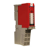
Allen-Bradley 1734-OB8S User Manual (236 pages)
Point Guard I/O Safety Modules
Brand:
Allen-Bradley
| Category:
Control Unit
| Size: 12.19 MB
Table of Contents
Additional Resources
14
Safety Precautions
17
Securing the System
18
POINT Guard I/O Modules in CIP Safety Systems
19
OB8S Safety Digital Output Module Features
20
Programming Requirements
21
Safety Application Requirements
22
POINT Guard I/O Analog Input Module
26
Single-Channel Mode
28
Dual-Channel Mode and Discrepancy Time
29
Dual-Channel, Equivalent
30
Dual-Channels, Complementary
31
Safety Input Fault Recovery
32
Safety Analog Inputs (1734-IE4S)
33
Digital Input Filter
34
Channel Offset
35
Using a Single-Channel Sensor
36
Dual-Channel Equivalent Mode
37
Tachometer Mode
38
Safety Outputs
39
Safety Outputs
40
Safety Output with Test Pulse
41
Dual-Channel Mode
42
Single-Channel Mode, 1734-OB8S Only
43
Muting Lamp Operation (1734-IB8S)
44
I/O Status Data
45
Digital I/O Status Data
46
Example 1: Isolating Field Power Segments
49
Example 2: POINT Guard I/O Used with AC I/O Modules
50
Placing Series a Digital and Analog Modules
51
Placing Series B Digital Modules
52
Install the Module Precautions
54
European Hazardous Location Approval
55
North American Hazardous Location Approval
56
Prevent Electrostatic Discharge
57
Connect the Module to the Mounting Base
59
Connect the Removable Terminal Block
60
Remove a Mounting Base
61
Terminal Layout
63
Connection Details
65
Wiring Examples
67
Single-Channel Safety Contactor
68
Dual-Channel Safety Contactors
69
Bipolar Safety Outputs
70
Safety Analog Input Wiring
71
Guardlogix Controller System Add and Configure the Ethernet Bridge
80
Add and Configure the 1734 Ethernet Adapter
81
Add and Configure Safety Digital Input Modules
84
Configure the Safety Digital Inputs
89
Configure the Test Outputs
92
Add and Configure Safety Digital Output Modules
93
Configure the Safety Digital Outputs
97
Add and Configure Safety Analog Input Modules
98
Rockwell Automation Publication 1734-UM013N-EN-P - September
99
Configure the Safety Analog Input Channel Operation
101
Configure the Safety Analog Inputs
102
Configure Safety Analog Input Alarms (Optional)
103
Configure Tachometer Operation
105
Values and States of Tags
107
Configure Safety Connections
109
Configuration Ownership
110
Save and Download the Module Configuration
111
Auto-Addressing with a 1734-PDN Adapter
116
Set up Your Devicenet Network
118
Configure the POINT Guard I/O Modules
119
Configure Digital Safety Outputs
122
Configure Safety Analog Inputs
123
Configure the Smartguard Controller
128
Complete the Set up of the Smartguard Controller
132
Save and Download Module Configuration
133
Determine if Devices Can be Verified
144
Select Devices to Verify
145
Review the Safety Device Verification Reports
147
O Modules Manually Setting the Safety Network Number
150
Resetting a Module to Out-Of-Box Condition
151
By Using the Logix Designer Application
152
By Using Rsnetworx for Devicenet Software
153
Exists' Enabled
154
Replacement with 'Configure Always' Enabled
159
Controller on a Devicenet Network
161
Module
166
Network Status
167
IE4S Safety Analog Input Status
168
OB8S Safety Output Status
169
Message Instructions
171
Configure the Message Instruction
172
Class, Instance, and Attribute Data for I/O Modules
173
Technical Specifications for Series a Modules
177
Safety Digital Output Module Specifications
179
Safety Analog Input Module Specifications
180
Technical Specifications for Series B Modules
189
Safety Digital Output Module Specifications
192
Safety Digital Output Module Specifications 1734-OBV2S
194
Environmental Specifications
196
Certifications
199
Series a Safety Data
202
Series B Safety Data
205
Product Failure Rates (Failures Per Hour)
209
Appendix E
212
Appendix E
213
Appendix E
214
Input Assemblies
215
Rockwell Automation Publication 1734-UM013N-EN-P - September
216
Configuration Assemblies
219
Using Data from Modules Configured Via the Generic Profile
225
Advertisement
Allen-Bradley 1734-OB8S Installation & User Manual (156 pages)
POINT Guard I/O Safety Modules
Brand:
Allen-Bradley
| Category:
I/O Systems
| Size: 5 MB
Table of Contents
Table of Contents
5
About the Specifications and Dimensions in this Manual
9
Common Techniques Used in this Manual
9
How to Use this Manual
9
Preface
9
Terminology
9
Additional Resources
10
Chapter 1
11
Introduction
11
POINT Guard I/O Overview
11
Before You Begin
12
Follow Precautions for Use
12
Understand Suitability for Use
12
I/O Module Overview
14
Precautions to Mount, Wire, and Clean
14
Safety System Architecture
15
CIP Safety Architectures
16
Safety Application Requirements
18
Safety Network Number
18
Safety Signature
18
Chapter 2
19
Introduction
19
Safety Functions
19
Safety I/O Modules
19
Safety Inputs
21
Using a Test Output with a Safety Input
21
Single Channel Mode
23
Dual-Channel Mode and Discrepancy Time
24
Dual-Channels, Equivalent
25
Dual-Channels, Complementary
26
Safety Input Fault Recovery
27
Input Delays
27
Safety Outputs
28
Safety Output with Test Pulse
28
Dual-Channel Setting
29
Safety Output Fault Recovery
29
Muting Lamp Operation (Test Outputs T1 and T3)
30
I/O Status Data
32
Requirements for Controlling Devices
33
Legislations and Standards
34
Europe
35
EC Directives
35
EMC Directive
36
North America
36
Japan
37
Safety Precautions
34
Chapter 3
39
Introduction
39
Install the Module
40
Environment and Enclosure
41
Preventing Electrostatic Discharge
41
Install the Mounting Base
42
Connect the Module to the Mounting Base
43
Connect the Removable Terminal Block
45
Remove a Mounting Base
46
Wire Modules
46
Set the Node Address of a POINT Guard I/O Module
48
Modules
50
Auto-Addressing with a 1734-PDN Adapter and POINT Guard I/O Modules
51
Reset POINT Guard I/O Modules to Out-Of-Box Condition
50
Chapter 4
53
Connection Details
53
Introduction
53
Examples of Wiring
55
Emergency Stop Dual-Channel Devices
55
Dual-Channel Safety Contactors
57
Chapter 5
59
Introduction
59
Pointbus Backplane
59
Power Supply Examples
60
Example 1: POINT Guard I/O Used with 1734-EP24DC for Input, 1734-FPD for Output - 24V DC Only I/O
61
Example 2: POINT Guard I/O Used with 1734-EP24DC for Input and Output, Plus AC I/O
62
Observing Precautions for Safe Use
63
Introduction
65
Add Modules to the I/O Configuration Tree
66
Add and Configure the Ethernet Bridge Module
66
Add and Configure the 1734-AENT Adapter
69
Add and Configure Safety Input Modules
72
Add and Configure Safety Output Modules
78
Chapter 6
66
Use Help
66
Values and States of Tags
85
Configure the Safety Tab
86
Configuration Ownership
88
Configuration Signature
88
Configure the Input Configuration Tab
89
Configure the Test Output Tab
92
Configure the Output Configuration Tab
93
Saving and Downloading Module Configuration
94
Before You Begin
95
Chapter 7
95
Introduction
95
Use Help
96
Work with Rsnetworx for Devicenet Software
96
Set up the Safety Configuration
98
Work with Inputs
98
Work with Outputs
102
Set up the Input and Output Connections of the Smartguard
104
Complete the Set up of the Smartguard Controller
108
Save and Download Module Configuration
109
Chapter 8
111
Considerations When Replacing POINT Guard I/O Modules
111
Why You Need to Manually Set the SNN
113
Guardlogix Controllers Versus Smartguard Controllers
114
What this Chapter Contains
111
Replacing an I/O Module When Using a Smartguard Controller
114
Replacing an I/O Module When Using a Guardlogix Controller
118
I/O Replacement with 'Configure Only When no Safety Signature
118
Exists' Enabled
118
I/O Replacement with 'Configure Always' Enabled
124
Chapter 9
127
Introduction
127
Configuration Lock
129
Module Status
129
Network Status
129
(1734-IB8S Module)
130
(1734-OB8S Module)
130
Power
130
Safe Input Status
130
Safe Output Status
130
Introduction
131
Message Instructions
131
Appendix A
132
Configure the Message Instruction
132
Appendix B Calculated Values
135
What this Appendix Contains
135
Understand Parameter Groups
137
What this Appendix Contains
137
Appendix D
139
Introduction
139
Appendix E
145
Input Assemblies
145
Introduction
145
Output Assemblies
146
Configuration Assemblies
147
Advertisement
Related Products
Allen-Bradley 1734-OBV2S
Allen-Bradley 1734-OB2
Allen-Bradley 1734-OB4
Allen-Bradley 1734-OB8
Allen-Bradley POINT I/O 1734-OB4K
Allen-Bradley POINT I/O 1734-OB8K
Allen-Bradley POINT I/O 1734-VTM
Allen-Bradley POINT I/O 1734-VHSC5
Allen-Bradley POINT I/O 1734-VHSC24
Allen-Bradley POINT I/O 1734-232ASC
Allen-Bradley Categories
Control Unit
Controller
I/O Systems
Switch
Power Supply
More Allen-Bradley Manuals
Login
Sign In
OR
Sign in with Facebook
Sign in with Google
Upload manual
Upload from disk
Upload from URL