
Related Manuals for Allen-Bradley 1734-IB8S


Summary of Contents for Allen-Bradley 1734-IB8S
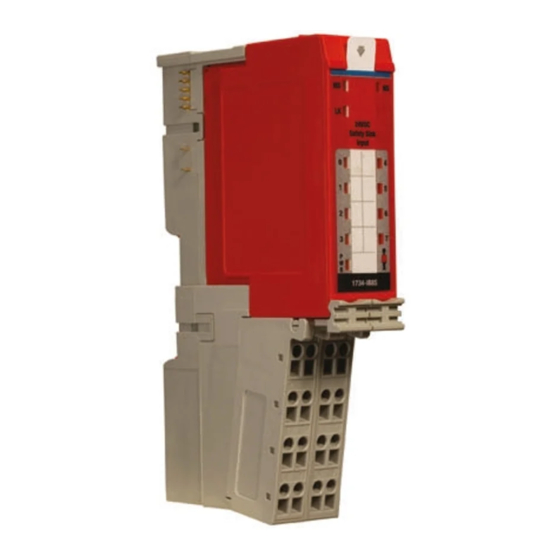
- Page 1 POINT Guard I/O Safety Modules Catalog Numbers 1734-IB8S, 1734-OB8S Installation & User Manual...
- Page 2 Labels may be on or inside the equipment, for example, a drive or motor, to alert people that surfaces may reach dangerous temperatures. Allen-Bradley, Rockwell Automation, POINT Guard I/O, POINTBus, POINT I/O, RSLogix 5000, RSLinx, RSNetWorx for DeviceNet, SmartGuard, GuardPLC, ControlLogix, GuardLogix, GuardShield, CompactBlock Guard I/O, Rockwell Automation, Stratix, 8000 and TechConnect are trademarks of Rockwell Automation, Inc.
- Page 3 Summary of Changes This manual contains new and updated information. Changes throughout this revision are marked by change bars, as shown to the right of this paragraph. New and Updated This table contains the changes made to this revision. Information Topic Page Muting lamp operation (test outputs T1 and T3)
- Page 4 Summary of Changes Notes: Rockwell Automation Publication 1734-UM013C-EN-P - August 2010...
-
Page 5: Table Of Contents
Table of Contents Preface How To Use This Manual ......... . 9 Common Techniques Used in This Manual . - Page 6 Table of Contents Chapter 3 Install the Module Introduction ........... . . 39 Environment and Enclosure .
- Page 7 (1734-IB8S module) ........
- Page 8 Table of Contents Appendix B Probability of Failure on What This Appendix Contains ........135 Demand (PFD), Probability of Calculated Values .
-
Page 9: Preface
Preface How To Use This Manual Read and understand this manual before using the POINT Guard I/O modules. Consult your Rockwell Automation representative if you have any questions or comments. Common Techniques Used These conventions are used throughout this manual: in This Manual •... -
Page 10: Additional Resources
Preface Additional Resources Refer to the following as needed for additional help when setting up and using your modules. For specifications refer to the relevant installation instructions. Resource Description POINT I/O Selection Guide, publication 1734-SG001 Provides selection information for POINT I/O modules. Additional publication references are listed as well. -
Page 11: Point Guard I/O Overview
POINT I/O one-piece mounting base (catalog number 1734-TOP, 1734-TOPS, 1734-TOP3, or 1734-TOP3S). IMPORTANT You need two mounting base assemblies for each 1734-IB8S or 1734-OB8S module. Do not use 1734-TB3 or 1734-TB3S mounting base assemblies. Rockwell Automation Publication 1734-UM013C-EN-P - August 2010... -
Page 12: Before You Begin
Chapter 1 POINT Guard I/O Overview Before You Begin Always observe the following guidelines when using a module, noting that in this manual we use safety administrator to mean a person qualified, authorized, and responsible to secure safety in the design, installation, operation, maintenance, and disposal of the ‘machine’: •... - Page 13 Chapter 1 POINT Guard I/O Overview ATTENTION: Follow these precautions for safe use. Wire conductors correctly and verify operation of the module before placing the system into operation. Incorrect wiring may lead to loss of safety function. Do not apply DC voltages exceeding the rated voltages to the module.
-
Page 14: Precautions To Mount, Wire, And Clean
Chapter 1 POINT Guard I/O Overview Precautions to Mount, Observe these precautions to prevent operation failure, malfunctions, or Wire, and Clean undesirable effects on product performance. Follow terminal base instructions for insertion and removal. Follow these precautions when wiring modules: •... -
Page 15: Safety System Architecture
Chapter 1 POINT Guard I/O Overview – Independently adjustable on and off delay is available per channel. • Test outputs (input modules only) – Separate test outputs are provided for short-circuit detection of a safety input (or inputs). – Power (24V) can be supplied to devices, such as safety sensors. –... -
Page 16: Cip Safety Architectures
Chapter 1 POINT Guard I/O Overview CIP Safety Architectures Use POINT Guard I/O modules in EtherNet/IP or DeviceNet safety architectures. Safety controllers control the safety outputs. Safety or standard PLC controllers can control the standard outputs. Figure 1 - POINT Guard I/O Modules in EtherNet/IP Safety Architecture Item Description GuardLogix controller... - Page 17 Chapter 1 POINT Guard I/O Overview Figure 2 - POINT Guard I/O Modules in DeviceNet Safety Architectures Item Description ControlLogix controller POINT I/O and POINTGuard I/O Guard I/O SmartGuard Safety communication Standard communication Rockwell Automation Publication 1734-UM013C-EN-P - August 2010...
-
Page 18: Safety Application Requirements
Chapter 1 POINT Guard I/O Overview Safety Application The POINT Guard I/O system is certified for use in safety applications up to Requirements and including Safety Integrity Level (SIL) 3 and Category (CAT) 4 in which the de-energized state is the safe state. Safety application requirements include evaluating probability of failure rates (PFD and PFH), system reaction time settings, and functional verification tests that fulfill SIL 3 criteria. -
Page 19: Safety Functions
Chapter Safety Functions Topic Page Introduction Safety I/O Modules Safety Inputs Safety Outputs I/O Status Data Requirements for Controlling Devices Safety Precautions Legislations and Standards Introduction Read this chapter for important information related to the safety functions of the modules. Also, refer to the brief overview on international standards and directives. - Page 20 Chapter 2 Safety Functions Figure 3 - Safety Status 44076 Item Description Inputs to Network Off Safety status Input Output off Networks The module is designed for use in applications where the safety state is the off state. Rockwell Automation Publication 1734-UM013C-EN-P - August 2010...
-
Page 21: Safety Inputs
T3M = Test Output 3 with Muting I0…I7 = Safety Inputs Figure 5 - Test Pulse in a Cycle For the 1734-IB8S module, the pulse width (X) is typically 525 μs; the pulse period (Y) is typically 144 ms. Rockwell Automation Publication 1734-UM013C-EN-P - August 2010... - Page 22 Chapter 2 Safety Functions When the external input contact is closed, a test pulse is output from the test output terminal to diagnose the field wiring and input circuitry. By using this function, short-circuits between inputs and 24V power, and between input signal lines and open circuits can be detected.
-
Page 23: Single Channel Mode
Chapter 2 Safety Functions Single Channel Mode If an error is detected, safety input data and safety input status turn off. Figure 7 - Normal Operation and Fault Detection (not to scale) Normal Test Output 0 Operation External Device Input Terminal 0 Safety Safety Input 0 Network... -
Page 24: Dual-Channel Mode And Discrepancy Time
Chapter 2 Safety Functions Dual-channel Mode and Discrepancy Time To support dual-channel safety devices, the consistency between signals on two channels can be evaluated. Either equivalent or complementary can be selected. This function monitors the time during which there is a discrepancy between the two channels. -
Page 25: Dual-Channels, Equivalent
Chapter 2 Safety Functions Dual-channels, Equivalent In Equivalent mode, both inputs of a pair should be in the same (equivalent) state. When a transition occurs in one channel of the pair prior to the transition of the second channel of the pair, a discrepancy occurs. If the second channel transitions to the appropriate state prior to the discrepancy time elapsing, the inputs are considered equivalent. -
Page 26: Dual-Channels, Complementary
Chapter 2 Safety Functions Dual-channels, Complementary In Complementary mode, the inputs of a pair should be in the opposite (complementary) state. When a transition occurs in one channel of the pair prior to the transition of the second channel of the pair, a discrepancy occurs. If the second channel transitions to the appropriate state prior to the discrepancy time elapsing, the inputs are considered complementary. -
Page 27: Safety Input Fault Recovery
Chapter 2 Safety Functions Safety Input Fault Recovery If an error is detected, the safety input data remains in the off state. Follow this procedure to activate the safety input data again. 1. Remove the cause of the error. 2. Place the safety input (or safety inputs) into the safe state. 3. -
Page 28: Safety Outputs
Chapter 2 Safety Functions Safety Outputs Read this section for information about safety outputs. Safety Output with Test Pulse When the safety output is on, the safety output can be configured to pulse test the safety output channel. By using this function, short-circuits between output signal lines and the power supply (positive side) and short-circuits between output signal lines can be detected. -
Page 29: Dual-Channel Setting
Chapter 2 Safety Functions Dual-channel Setting When the data of both channels is in the on state, and neither channel has a fault, the outputs are turned on. The status is normal. If a fault is detected on one channel, the safety output data and individual safety output status turn off for both channels. -
Page 30: Muting Lamp Operation (Test Outputs T1 And T3)
Chapter 2 Safety Functions Muting Lamp Operation Beginning with firmware revision 1.2, we made changes to the operation of the (test outputs T1 and T3) muting status bits for the test outputs T1 and T3. Test outputs T1 and T3 are controlled by your PLC processor program to illuminate a muting lamp. - Page 31 T1 and T3. Keep these points in mind as well: • When power is applied to the 1734-IB8S module, and T1 or T3 remains commanded off, the muting status defaults to on.
-
Page 32: I/O Status Data
Chapter 2 Safety Functions I/O Status Data In addition to I/O data, the module provides status data for monitoring the I/O circuits. The status includes the following data, which can be read by the controllers. Note that 1 = ON/Normal and 0 = OFF/Fault/Alarm: •... -
Page 33: Requirements For Controlling Devices
Safety level. Table 3 - Controlling Device Requirements Device Requirement Allen-Bradley Bulletin Safety Components Emergency stop switches Use approved devices with direct opening mechanisms complying Bulletin 800F, 800T with IEC/EN 60947-5-1. Door interlocking... -
Page 34: Safety Precautions
Chapter 2 Safety Functions Safety Precautions ATTENTION: As serious injury may occur due to loss of required safety function, follow these safety precautions. • Do not use test outputs of the modules as safety outputs. • Do not use Ethernet, DeviceNet, or ControlNet standard I/O data or explicit message data as safety data. -
Page 35: Europe
IP54 protection when applied in Zone 2 environments. • This equipment shall be used within its specified ratings defined by Allen-Bradley. • Provision shall be made to prevent the rated voltage from being exceeded by transient disturbances of more than 40% when applied in Zone 2 environments. -
Page 36: Emc Directive
Chapter 2 Safety Functions EMC Directive Rockwell Automation devices that comply with EC directives also conform to the related EMC standards so that they can more easily be built into other devices or the overall machine. The actual products have been checked for conformity to EMC standards. -
Page 37: Japan
Chapter 2 Safety Functions North American Hazardous Location Approval The following information applies when Informations sur l’utilisation de cet operating this equipment in hazardous équipement en environnements dangereux. locations. Products marked "CL I, DIV 2, GP A, B, C, D" are suitable Les produits marqués "CL I, DIV 2, GP A, B, C, D"... - Page 38 Chapter 2 Safety Functions Notes: Rockwell Automation Publication 1734-UM013C-EN-P - August 2010...
-
Page 39: Introduction
Chapter Install the Module Topic Page Introduction Environment and Enclosure Preventing Electrostatic Discharge Install the Mounting Base Connect the Module to the Mounting Base Connect the Removable Terminal Block Remove a Mounting Base Wire Modules Set the Node Address of a POINT Guard I/O Module Reset POINT Guard I/O Modules to Out-of-box Condition Auto-addressing with a 1734-PDN Adapter and POINT Guard I/O Modules... -
Page 40: Install The Module
Chapter 3 Install the Module Figure 14 - POINT Guard I/O Modules 31867-M Item Description Slide-in writeable labels Insertable I/O modules Module locking mechanism Rockwell Automation Publication 1734-UM013C-EN-P - August 2010... -
Page 41: Environment And Enclosure
In addition to this publication, see: • Industrial Automation Wiring and Grounding Guidelines, for additional installation requirements, Allen-Bradley publication 1770-4.1. • NEMA Standards 250 and IEC 60529, as applicable, for explanations of the degrees of protection provided by different types of enclosure. -
Page 42: Install The Mounting Base
Chapter 3 Install the Module WARNING: If you connect or disconnect wiring while the field- side power is on, an electrical arc can occur. This could cause an explosion in hazardous location installations. Be sure that power is removed or the area is nonhazardous before proceeding. This equipment shall be used within its specified ratings defined by Rockwell Automation. -
Page 43: Connect The Module To The Mounting Base
Chapter 3 Install the Module 2. Slide the mounting base down, allowing the interlocking side pieces to engage the adjacent module, power supply, or adapter. Slide the mounting base to let the interlocking side pieces engage the adjacent module or adapter. 31868-M 3. - Page 44 Install the Module Item Description Mounting base assembly Keyswitch 1734-IB8S Module Key 1 = 8 (left); Key 2 = 1 (right) 1734-OB8S Module Key 1 = 8 (left); Key 2 = 2 (right) Locking mechanism 2. Make certain the DIN-rail (orange) locking screw is in the horizontal position, noting that you cannot insert the module if the mounting-base locking mechanism is unlocked.
-
Page 45: Connect The Removable Terminal Block
Chapter 3 Install the Module Connect the Removable If a removable terminal block (RTB) is supplied with your mounting base Terminal Block assembly, you need to remove it by pulling up on the RTB handle. This lets you remove and replace the base as necessary without removing any of the wiring. WARNING: When you connect or disconnect the RTB with field- side power applied, an electrical arc can occur. -
Page 46: Remove A Mounting Base
Chapter 3 Install the Module Remove a Mounting Base To remove a mounting base, you must remove any installed module and the module installed in the base to the right. If the mounting base has a removable terminal base (RTB), unlatch the RTB handle on the I/O module and pull on the handle to remove the RTB. - Page 47 Chapter 3 Install the Module Figure 15 - 1734-IB8S Field Connections 1734-TOP and 1734-TB Bases Shown Where: T0 = Test Output 0 T1M = Test Output 1 with Muting T2 = Test Output 2 T3M = Test Output 3 with Muting I0…I7 = Inputs 0…7...
-
Page 48: Set The Node Address Of A Point Guard I/O Module
Chapter 3 Install the Module Set the Node Address of a Use RSNetWorx for DeviceNet software to set the node address of POINT POINT Guard I/O Module Guard I/O modules. The module has an out-of-box preset node address of 63. We suggest that you connect and set the modules one at a time. - Page 49 Chapter 3 Install the Module 4. Browse to the DeviceNet network, being sure to not click OK when the browse is complete. If you are unable to browse the DeviceNet network and see the POINT Guard modules, the modules may have been previously configured to an incompatible data rate or node address.
-
Page 50: Reset Point Guard I/O Modules To Out-Of-Box Condition
Chapter 3 Install the Module Reset POINT Guard I/O It may be helpful to reset your POINT Guard I/O module to an out-of-box Modules to Out-of-box condition before setting the modules node address on the DeviceNet network by using the node commissioning tool. For example, if your POINT Guard I/O Condition module had a previous safety-connection owner, the module will not make a safety connection to a new owner until the previous owner is cleared via a reset. -
Page 51: Auto-Addressing With A 1734-Pdn Adapter And Point Guard I/O Modules
Chapter 3 Install the Module Auto-addressing with a Sequential auto-addressing is where the leftmost node address is configured and a 1734-PDN Adapter and parameter is set in that module that automatically addresses nodes to the right of the module. The leftmost node can be a POINT Guard I/O module or a POINT Guard I/O Modules standard POINT I/O module. - Page 52 Chapter 3 Install the Module Notes: Rockwell Automation Publication 1734-UM013C-EN-P - August 2010...
-
Page 53: Introduction
Chapter Wire the Module Topic Page Introduction Connection Details Examples of Wiring Introduction Read this chapter for information about wiring and safety categories. Connection Details See the tables that show input device connection methods and their safety categories. Connected Device Test Pulse Connection Schematic Diagram Safety... - Page 54 Chapter 4 Wire the Module Connected Device Test Pulse Connection Schematic Diagram Safety from Test Category Output Emergency stop Connect the device button between I0 and T0, and I1 and T1. Door monitoring switch Connect the devices between T0 and I0 and I1, noting that T0 is configured for 24V power supply.
-
Page 55: Examples Of Wiring
Chapter 4 Wire the Module Examples of Wiring Read this section for examples of wiring by application. See catalog number details for the appropriate module. Emergency Stop Dual-channel Devices This example shows wiring and controller configuration when using a POINT Guard I/O module with an emergency stop button and gate monitoring switch that have dual-channel contacts. - Page 56 Chapter 4 Wire the Module Single Channel Safety Contactor This example shows wiring and controller configuration when using a POINT Guard I/O module with a single safety contactor. When used in combination with the programs of the safety controller, this circuit configuration is Safety Category 2.
-
Page 57: Dual-Channel Safety Contactors
Chapter 4 Wire the Module Dual-channel Safety Contactors This example shows wiring and controller configuration when using a POINT Guard I/O module with redundant safety contactors. When used in combination with the programs of the safety controller, this circuit configuration is Safety Category 4. Additional wiring, such as monitoring feedback, may be required to achieve Safety Category 4 Figure 19 - POINT Guard I/O Module Wiring (redundnt safety contacts). - Page 58 Chapter 4 Wire the Module Notes: Rockwell Automation Publication 1734-UM013C-EN-P - August 2010...
-
Page 59: Introduction
Chapter Power Supply Examples Topic Page Introduction POINTBus Backplane Power Supply Examples Observing Precautions for Safe Use Introduction A POINT Guard I/O system includes an adapter, I/O modules, mounting bases, and power distribution modules. POINT I/O adapters have built-in power supplies. -
Page 60: Power Supply Examples
You must define the requirements for your application, for segmenting field and bus power. • POINT Guard I/O does not require separate field-bus power usage, that is, separate power supplies for the 1734-IB8S and 1734-OB8S modules. This is optional. • POINT Guard I/O does not require separate POINTBus... -
Page 61: Example 1: Point Guard I/O Used With 1734-Ep24Dc For Input, 1734-Fpd For Output - 24V Dc Only I/O
Chapter 5 Power Supply Examples Example 1: POINT Guard I/O Used with 1734-EP24DC for Input, 1734-FPD for Output - 24V DC Only I/O This power supply example uses a 1734-EP24DC expansion power supply and 1734-FPD field power distributor to power I/O with these properties: •... -
Page 62: Example 2: Point Guard I/O Used With 1734-Ep24Dc For Input And Output, Plus Ac I/O
Chapter 5 Power Supply Examples Example 2: POINT Guard I/O Used with 1734-EP24DC for Input and Output, Plus AC I/O This power supply example uses a 1734-EP24DC input and output with these properties: • Group 1 and Group 3 I/O have separate functioning groups of I/O, compared to Group 2. -
Page 63: Observing Precautions For Safe Use
Chapter 5 Power Supply Examples Observing Precautions for Use these guidelines to be sure of proper product use: Safe Use • Do not apply AC voltage to the POINT Guard I/O modules. • Wire conductors correctly and verify operation of the module before commissioning the system in which the module is incorporated. - Page 64 Chapter 5 Power Supply Examples Notes: Rockwell Automation Publication 1734-UM013C-EN-P - August 2010...
-
Page 65: Introduction
Chapter Configure the Module in a GuardLogix Controller Topic Page Introduction Use Help Add Modules to the I/O Configuration Tree Add and Configure the Ethernet Bridge Module Add and Configure the 1734-AENT Adapter Add and Configure Safety Input Modules Add and Configure Safety Output Modules Values and States of Tags Configure the Safety Tab Configuration Ownership... -
Page 66: Use Help
Chapter 6 Configure the Module in a GuardLogix Controller Use Help At the bottom of each dialog box, click Help for information about how to complete entries in that dialog box. At the bottom of warning dialog boxes, click Help for information about that specific error. Add Modules to the When first setting up your POINT Guard I/O modules for use with the I/O Configuration Tree... - Page 67 Chapter 6 Configure the Module in a GuardLogix Controller 2. Expand the Communications option, select one of these Ethernet bridge modules, and click OK. Cat. No. Description 1756-EN2F/A 1756 10/100 Mbps Ethernet bridge, fiber media 1756-EN2T/A 1756 10/100 Mbps Ethernet bridge, twisted-pair media 1756-ENBT/A 1756 10/100 Mbps Ethernet bridge, twisted-pair media 1756-EN2TR...
- Page 68 Chapter 6 Configure the Module in a GuardLogix Controller This New Module dialog box appears. 4. In the Name box, type the appropriate name of the Ethernet bridge module. 5. In the Description box, enter an optional description of the Ethernet bridge module.
-
Page 69: Add And Configure The 1734-Aent Adapter
Chapter 6 Configure the Module in a GuardLogix Controller Add and Configure the 1734-AENT Adapter Follow these steps to add and configure the 1734-AENT adapter. 1. Right-click the Ethernet connection and choose New Module. The Select Module dialog box appears. 2. - Page 70 Chapter 6 Configure the Module in a GuardLogix Controller This New Module dialog box appears. 3. In the Name box, type the appropriate name of the 1734-AENT adapter. 4. In the Description box, enter an optional description of the 1734-AENT adapter.
- Page 71 Chapter 6 Configure the Module in a GuardLogix Controller 9. In the Revision boxes, enter the appropriate major and minor revision of the 1734-AENT adapter. IMPORTANT 1734-AENT adapter firmware must be major revision 3 or later to support POINT Guard I/O modules. 10.
-
Page 72: Add And Configure Safety Input Modules
Chapter 6 Configure the Module in a GuardLogix Controller 13. Click OK. You return to the Module Properties dialog box. 14. Click OK to apply your changes. The I/O Configuration tree displays the 1734-AENT adapter. Add and Configure Safety Input Modules Follow these steps to add and configure POINT Guard I/O safety modules. - Page 73 Configure the Module in a GuardLogix Controller The Select Module dialog box displays a list that includes Safety. 2. Select the appropriate input module, such as 1734-IB8S, and click OK. The New Module dialog box appears. 3. In the Name box, type a unique name for the input module.
- Page 74 Chapter 6 Configure the Module in a GuardLogix Controller 6. In the Safety Network Number box, use the default setting. For a detailed explanation of the safety network number (SNN), see the GuardLogix Controller Systems Safety Reference Manual, publication 1756-RM093, noting that in most cases, you use the default provided by the RSLogix 5000 software.
- Page 75 Chapter 6 Configure the Module in a GuardLogix Controller 12. From the Input Data pull-down menu, choose the appropriate method for the input module, Safety or None. Choose Description Safety These tags are created for the target module: • RunMode for module mode •...
- Page 76 Chapter 6 Configure the Module in a GuardLogix Controller 14. From the Input Status pull-down menu, choose the appropriate method for the input module from the following options. Choose Description None There are no status tags, only data for the inputs. Pt.
- Page 77 Chapter 6 Configure the Module in a GuardLogix Controller Choose Description Pt. Status - Muting There is a muting status tag for test output T1 and T3 with point status for each input point. • Status tags for each of the input points. Pt.
-
Page 78: Add And Configure Safety Output Modules
Configure the Module in a GuardLogix Controller 17. Click OK to apply your changes. The I/O Configuration tree displays the 1734-IB8S module. Add and Configure Safety Output Modules Follow these steps to add and configure POINT Guard I/O safety modules. - Page 79 Chapter 6 Configure the Module in a GuardLogix Controller The Select Module dialog box displays a list that includes Safety. 2. Select the appropriate output module, such as 1734-OB8S, and click OK. The New Module dialog box appears. 3. In the Name box, type a unique name for the output module. 4.
- Page 80 Chapter 6 Configure the Module in a GuardLogix Controller 6. In the Safety Network Number box, use the default setting. For a detailed explanation of the safety network number (SNN), see the GuardLogix Controller Systems Safety Reference Manual, publication 1756-RM093, noting that in most cases, you use the default provided by the RSLogix 5000 software.
- Page 81 Chapter 6 Configure the Module in a GuardLogix Controller 12. From the Input Data pull-down menu, choose the appropriate method for the output module, None. Choose Description None This is an output-only safety module. None is the only valid selection. 13.
- Page 82 Chapter 6 Configure the Module in a GuardLogix Controller Choose Description • A single BOOL tag represents an AND of the status bits for all Combined Status - Muting the output points. For example, if any output channel has a fault, this bit goes LO.
- Page 83 Chapter 6 Configure the Module in a GuardLogix Controller Choose Description Pt. Status - Muting There is a muting status tag for test output T1 and T3 with point status for each output point. • Status tags for each of the output points. Pt.
- Page 84 Chapter 6 Configure the Module in a GuardLogix Controller The I/O Configuration tree displays the 1734-OB8S module. Rockwell Automation Publication 1734-UM013C-EN-P - August 2010...
-
Page 85: Values And States Of Tags
Chapter 6 Configure the Module in a GuardLogix Controller Values and States of Tags This table shows the values and states of the tags. Data Description Input Safety Input Data Indicates the ON/OFF state of each input circuit. data SAFETY •... -
Page 86: Configure The Safety Tab
Chapter 6 Configure the Module in a GuardLogix Controller Configure the Safety Tab Read this for information about how to complete entries when you click the Safety tab. 1. From the Module Properties dialog box, click the Safety tab. 2. Click Advanced. The Advanced Connection Reaction Time Limit Configuration dialog box appears. - Page 87 Chapter 6 Configure the Module in a GuardLogix Controller The smallest input RPI allowed is 6 ms. Selecting small RPIs consumes network bandwidth and may cause nuisance trips because other devices cannot get access to the network. As an example, a safety input module with only E-stop switches connected may generally work well with settings of 50…100 ms.
-
Page 88: Configuration Ownership
Chapter 6 Configure the Module in a GuardLogix Controller Configuration Ownership The connection between the owner and the POINT Guard I/O module is based on the following: • POINT Guard I/O module number • POINT Guard I/O safety network number •... -
Page 89: Configure The Input Configuration Tab
Chapter 6 Configure the Module in a GuardLogix Controller Configure the Follow this procedure to complete the input configuration. Refer to Chapter 2 Input Configuration Tab for related information. 1. From the Module Properties dialog box, click the Input Configuration tab. 2. - Page 90 Chapter 6 Configure the Module in a GuardLogix Controller A ‘cycle inputs’ required condition occurs when one input terminal goes from its normal Active->Inactive->Active state while the other input terminal remains in its normal Active state. Even though no fault is declared, the inputs must be cycled before the evaluated status of the inputs can return to the Active state.
- Page 91 Chapter 6 Configure the Module in a GuardLogix Controller 5. Assign the Input Delay Time, Off -> On (0…126 ms, in increments of 6 ms). Filter time is for OFF to ON transition. Input must be HI after input delay has elapsed before it is set logic 1.
-
Page 92: Configure The Test Output Tab
Chapter 6 Configure the Module in a GuardLogix Controller Configure the This section describes how to work with the Test Output Configuration dialog Test Output Tab box. Refer to this table for information on configuring test outputs. Follow this procedure to complete the test output configuration. 1. -
Page 93: Configure The Output Configuration Tab
Chapter 6 Configure the Module in a GuardLogix Controller Configure the This section provides a procedure for configuring safety outputs by using the Output Configuration Tab information in this table and completing the entries referring to the figure. Follow this procedure to complete the safety output configuration. 1. -
Page 94: Saving And Downloading Module Configuration
Chapter 6 Configure the Module in a GuardLogix Controller 4. From the Output Error Latch Time box, enter the time the module holds an error to make sure the controller can detect it (0…65,530 ms, in increments of 10 ms - default 1000 ms). This provides you more reliable diagnostics and enhances the changes that a nuisance error is detected. -
Page 95: Introduction
To download the appropriate EDS file, visit the EDS Hardware and Installation website at http:// www.rockwellautomation.com/resources/eds/. The EDS file for the 1734-IB8S module is 0010023000F0100. The EDS file for the 1734-OB8S module is 001002300100100. Rockwell Automation Publication 1734-UM013C-EN-P - August 2010... -
Page 96: Use Help
Chapter 7 Configure the Module for a SmartGuard Controller Use Help For information about RSNetWorx for DeviceNet software, from the Help menu, choose RSNetWorx Help. Work with RSNetWorx for Before you begin to design a project with RSNetWorx for DeviceNet software, DeviceNet Software follow these procedures. - Page 97 Chapter 7 Configure the Module for a SmartGuard Controller 4. From the Networks menu, choose Online. 5. Select the SmartGuard driver and click OK. This dialog box appears. Rockwell Automation Publication 1734-UM013C-EN-P - August 2010...
-
Page 98: Set Up The Safety Configuration
Chapter 7 Configure the Module for a SmartGuard Controller 6. Click OK. RSNetWorx for DeviceNet software finds the SmartGuard and POINT Guard I/O modules on the DeviceNet network. 7. Click the online icon again to go offline. Set Up the Use this procedure to set up the Safety Configuration tab. - Page 99 Chapter 7 Configure the Module for a SmartGuard Controller 2. Click the Safety Configuration tab. 3. Double-click Input Points 00/01, noting that inputs 00 and 01 are the E-stop pushbuttons. Rockwell Automation Publication 1734-UM013C-EN-P - August 2010...
- Page 100 Chapter 7 Configure the Module for a SmartGuard Controller 4. Edit the parameters so that the channels are pulse tested by Test sources 0 and 1, respectively. 5. Double-click Input Points 00/01 to minimize and Input Points 02/03 to expand. Rockwell Automation Publication 1734-UM013C-EN-P - August 2010...
- Page 101 Chapter 7 Configure the Module for a SmartGuard Controller Note the following: • Light curtain is connected to inputs 02 and 03. • GuardShield pulse tests OSSD1 and OSSD2, so these inputs will be configured as Safety Inputs. 6. Double-click Input Points 02/03 to minimize. 7.
-
Page 102: Work With Outputs
Chapter 7 Configure the Module for a SmartGuard Controller 9. Add the AUX feedback circuit for the redundant safety contactors to input 05, making it a safety input as it is not being pulse tested. 10. Double-click Input Points 04/05 to minimize. Work with Outputs 1. - Page 103 Chapter 7 Configure the Module for a SmartGuard Controller 2. Configure them as Safety Pulse test. 3. Click Apply and OK to return to the main RSNetWorx for DeviceNet dialog box. Rockwell Automation Publication 1734-UM013C-EN-P - August 2010...
-
Page 104: Set Up The Input And Output Connections Of The Smartguard
Chapter 7 Configure the Module for a SmartGuard Controller Set Up the Input and Output Use this procedure to set up the input and output connections of the SmartGuard Connections of the controller. SmartGuard Controller 1. In RSNetWorx for DeviceNet software, right-click the SmartGuard controller and choose Properties. - Page 105 Chapter 7 Configure the Module for a SmartGuard Controller 3. Right-click the POINT Guard I/O module and choose Add Connection. The Add Safety Connection dialog box appears. You can add individual safety connections for the inputs and outputs. The SmartGuard 600 controller can have up to 32 connections. Rockwell Automation Publication 1734-UM013C-EN-P - August 2010...
- Page 106 Chapter 7 Configure the Module for a SmartGuard Controller 4. To add a safety connection, from the Connection Name pull-down menu, choose one of these options. Choose Description [IN] Safety Control of safety inputs • Control of safety inputs [IN] Safety + •...
- Page 107 3…9 for each connection, being sure to assign input and output connections. Notice that the connections for the 1734-IB8S module have 2 bytes. If you had selected individual point status, the input connection would be 5 bytes. 11. Click Apply.
-
Page 108: Complete The Set Up Of The Smartguard Controller
Chapter 7 Configure the Module for a SmartGuard Controller Complete the Set Up of the SmartGuard Controller 1. From the 1752-L24BBB dialog box, click Apply and then OK to accept the connection. 2. Place RSNetWorx from DeviceNet software back into Online mode. a. -
Page 109: Save And Download Module Configuration
Chapter 7 Configure the Module for a SmartGuard Controller Save and Download We recommend that after a module is configured you save your work. Module Configuration If after downloading the program the MS and NS status indicators on the POINT Guard I/O module are not both solid green, this may be due to loss of ownership. - Page 110 Chapter 7 Configure the Module for a SmartGuard Controller Notes: Rockwell Automation Publication 1734-UM013C-EN-P - August 2010...
-
Page 111: What This Chapter Contains
Chapter Considerations When Replacing POINT Guard I/O Modules What This Chapter Contains This chapter provides things to consider when replacing POINT Guard I/O modules when they are connected to GuardLogix or SmartGuard controllers. For more information, refer to the GuardLogix Controllers User Manual, publication 1756-UM020 and the SmartGuard 600 Controllers User Manual, publication 1752-UM001. - Page 112 Chapter 8 Considerations When Replacing POINT Guard I/O Modules The following, simplified example is of CompactBlock Guard I/O on a DeviceNet network. Your products may differ, but the function is the same. EXAMPLE The DeviceNet network supports 64 node numbers, so if you have 100 devices on multiple DeviceNet networks, there are at least 36 duplicate node numbers being used.
-
Page 113: Why You Need To Manually Set The Snn
Chapter 8 Considerations When Replacing POINT Guard I/O Modules Why You Need to Manually Set the SNN The examples above showed how the SNN is used to guarantee safety-connection integrity after the system is operational. But the SNN is also used to guarantee integrity on the initial download to the POINT Guard I/O module. -
Page 114: Guardlogix Controllers Versus Smartguard Controllers
Chapter 8 Considerations When Replacing POINT Guard I/O Modules GuardLogix Controllers versus SmartGuard Controllers There is one major difference in functionality between the GuardLogix and SmartGuard safety controllers that affects the replacement of safety I/O modules. GuardLogix controllers retain I/O module configuration on-board and are able to download the configuration to the replacement module. - Page 115 Chapter 8 Considerations When Replacing POINT Guard I/O Modules 3. Right-click the module and choose Download to Device. This dialog box appears. 4. Click Yes. This dialog box appears informing you that the SNN of the replacement module does not match the SNN in the software. 5.
- Page 116 Chapter 8 Considerations When Replacing POINT Guard I/O Modules 6. Click OK. This dialog box appears, confirming that the SNN has ben set. The download now occurs. Once completed successfully, you see this message in the main project view: ‘The device at address xx has been downloaded.
- Page 117 Chapter 8 Considerations When Replacing POINT Guard I/O Modules If the configuration downloaded to the module was not from the original DNT file, the configuration signature will not match the original. Even if you recreate the same parameters in a new DNT file, the time and date portions of the signature will be different so the connection to the SmartGuard controller is not made.
-
Page 118: Replacing An I/O Module When Using A Guardlogix Controller
Chapter 8 Considerations When Replacing POINT Guard I/O Modules Replacing an I/O Module Follow the appropriate steps to replace an I/O module when using a GuardLogix When Using a GuardLogix controller. Controller I/O Replacement with ‘Configure Only When No Safety Signature Exists’... - Page 119 Chapter 8 Considerations When Replacing POINT Guard I/O Modules Once the correct SNN has been downloaded to the POINT Guard I/O module, the GuardLogix controller automatically configures the module. If the project is configured as ‘Configure Only When No Safety Signature Exists’ , follow the appropriate steps to replace a POINT Guard I/O module based on your scenario.
- Page 120 Chapter 8 Considerations When Replacing POINT Guard I/O Modules Scenario 1 - New Module is Out-of-box and Safety Signature Exists 1. Remove the old I/O module and install the new module. 2. Right-click your POINT Guard I/O module and choose Properties. 3.
- Page 121 Chapter 8 Considerations When Replacing POINT Guard I/O Modules Scenario 2 - New Module SNN is Different from Original and Safety Signature Exists 1. Remove the old I/O module and install the new module. 2. Right-click your POINT Guard I/O module and choose Properties. 3.
- Page 122 Chapter 8 Considerations When Replacing POINT Guard I/O Modules 8. Click Set. The Set Safety Network Number in Module confirmation dialog box appears. 9. Verify that the Network Status (NS) status indicator is alternating red/ green on the correct module before clicking Yes to set the SNN and accept the replacement module.
- Page 123 Chapter 8 Considerations When Replacing POINT Guard I/O Modules Scenario 3 - New Module SNN is Different from Original and No Safety Signature Exists 1. Remove the old I/O module and install the new module. 2. Right-click your POINT Guard I/O module and choose Properties. 3.
-
Page 124: I/O Replacement With 'Configure Always' Enabled
Chapter 8 Considerations When Replacing POINT Guard I/O Modules I/O Replacement with ‘Configure Always’ Enabled From the Controller Properties dialog box, choose ‘Configure Always’ . ATTENTION: Enable the ‘Configure Always’ feature only if the entire CIP Safety Control System is not being relied on to maintain SIL 3 behavior during the replacement and functional testing of a module. - Page 125 Chapter 8 Considerations When Replacing POINT Guard I/O Modules For modules with different SNNs, clicking Reset Ownership places the module in an out-of-box condition. Once in out-of-box mode, no action is needed for the GuardLogix controller to take ownership of the module. Rockwell Automation Publication 1734-UM013C-EN-P - August 2010...
- Page 126 Chapter 8 Considerations When Replacing POINT Guard I/O Modules If the project is configured for ‘Configure Always’ , follow the appropriate steps to replace a POINT Guard I/O module based on your scenario. GuardLogix/ Replacement Fault Action Required RSLogix 5000 Module SNN Safety Signature Exists...
-
Page 127: Introduction
Status Indicators Topic Page Module Status Network Status Configuration Lock Power Safe Input Status (1734-IB8S module) Safe Output Status (1734-OB8S module) Introduction Refer to the appropriate status indicators on the following pages as necessary. Rockwell Automation Publication 1734-UM013C-EN-P - August 2010... - Page 128 Chapter 9 Status Indicators Figure 22 - Status Indicators Placement Item Description Network status indicator Input/output 4 Input/output 5 Input/output 6 Input/output 7 Field Power status indicator Input/output 3 Input/output 2 Input/output 1 Input/output 0 Configuration lock status indicator Module status indicator Rockwell Automation Publication 1734-UM013C-EN-P - August 2010...
-
Page 129: Module Status
Chapter 9 Status Indicators Module Status Indicator Status Description Recommended Action No power is applied to the module. Apply power to this connector. Solid green The module is operating normally. None. Solid red The module detected an unrecoverable fault. Cycle power to the module. If problem persists, replace the module. -
Page 130: Power
Normal condition, field power supplied and within None. specification. Yellow Field power out of specification. Check your connectors, wiring, and voltages. Safe Input Status (1734-IB8S module) Indicator Status Description Recommended Action 0…7 Safety input is off, or module is being configured. -
Page 131: Introduction
Appendix Get I/O Diagnostic Status from Modules in Logix Systems Topic Page Introduction Message Instructions Introduction You can use message instructions in a Logix system to determine the cause of input point or output point faults. Message Instructions When the controller detects a fault on an input or output point, you can use a message instruction to explicitly retrieve the cause of the fault. -
Page 132: Configure The Message Instruction
Appendix A Get I/O Diagnostic Status from Modules in Logix Systems This sample ladder logic is monitoring the status of output point 3. This ladder logic rung examines the Output Point Status and, when a fault is detected (0 = error), the message instruction is executed. Configure the Follow this procedure to edit the Message Configuration dialog box. - Page 133 Appendix A Get I/O Diagnostic Status from Modules in Logix Systems 4. Refer to the appropriate table, depending on what you’d like to monitor. This dialog box illustrates values you enter to determine the reason for the fault on Output 3. When entering the Instance value, enter the input/output point plus 1.
- Page 134 Appendix A Get I/O Diagnostic Status from Modules in Logix Systems Service Function Command (hex) Response (hex) Type Service Class Instance Attribute Data Code Size Reads the cause for 01…08 0: No error Attribute the safety output 01: Configuration invalid Single fault specified by the 02: Over current detected...
-
Page 135: What This Appendix Contains
Appendix Probability of Failure on Demand (PFD), Probability of Failure per Hour (PFH), and Mean Time Between Failure (MTBF) Data What This Appendix This appendix lists calculated values for probability of failure on demand, Contains probability of failure per hour, and mean time between failure. Calculated Values See the table that shows the values. - Page 136 10% of SIL 3 Limit 1.00E-04 1.00E-03 1.00E-02 Proof Test Interval (years) Model Proof Test Interval PFD (1/hour) PFH (1/hour) MTBF (hour) (Mission Time) Year Hour 1734-IB8S 8760 5.85E-07 17520 1.17E-06 43800 2.93E-06 1.34E-10 5.76E+06 87600 5.86E-06 175200 1.17E-05 1734-OB8S 8760 6.05E-07...
-
Page 137: What This Appendix Contains
Appendix Configuration Reference Information What This Appendix This appendix provides information about configuration settings. Contains Understand Parameter The modules have these parameter groups: safety input, test output, safety Groups output. See the tables for the settings in each parameter group. All parameters are set by using RSLogix 5000 software. - Page 138 Appendix C Configuration Reference Information Parameter Name Value Description Default Test Output Mode Not Used An external device is not connected. Not Used Standard The output is connected to a standard device. Pulse Test A contact output device is connected. Use in combination with a safety input.
-
Page 139: Introduction
Specifications Topic Page 1734-IB8S and 1734-OB8S Physical Specifications 1734-OB8S - Technical Specifications 1734-IB8S and 1734-OB8S - Technical Specifications 1734-IB8S and 1734-OB8S Physical Specifications 1734-IB8S and 1734-OB8S Environmental Specifications 1734-IB8S and 1734-OB8S Certifications Introduction Refer to the appropriate module specifications as necessary. - Page 140 Appendix D Specifications Table 5 - 1734-IB8S Technical Specifications Attribute Value Pulse Test Output Output type Current sourcing Number of sources (T0, T1M, T2, T3M) Test output current (each output point) 0.7 A max Aggregate current of test outputs per module 2.8 A @ 40 °C (104 °F)
- Page 141 Table 8 - 1734-IB8S and 1734-OB8S Physical Specifications Attribute Value Keyswitch positions (left and right) 1734-IB8S: Key 1 = 8 (left); Key 2 = 1 (right) 1734-OB8S: Key 1 = 8 (left); Key 2 = 2 (right) Pilot duty rating Not rated (1734-OB8S only)
- Page 142 Appendix D Specifications Table 8 - 1734-IB8S and 1734-OB8S Physical Specifications Attribute Value IEC temp code Enclosure type rating None (open-style) Wiring category 2 - on signal ports Wire size Determined by installed terminal block Weight, approx. 62.4 g (2.2 oz) Dimensions (HxWxD), approx.
- Page 143 Appendix D Specifications Table 9 - 1734-IB8S and 1734-OB8S Environmental Specifications Attribute Value EFT/B immunity IEC 61000-4-4: ±3 kV at 5 kHz on signal ports Surge transient immunity IEC 61000-4-5: ±1 kV line-line (DM) and ±2 kV line-earth (CM) on signal...
- Page 144 Appendix D Specifications Notes: Rockwell Automation Publication 1734-UM013C-EN-P - August 2010...
-
Page 145: Introduction
Instance Module Connection Byte Bit 7 Bit 6 Bit 5 Bit 4 Bit 3 Bit 2 Bit 1 Bit 0 Hex (decimal) Type 1734-IB8S Safety and Safety Safety Safety Safety Safety Safety Safety Safety Standard Input 7 Input 6 Input 5... -
Page 146: Output Assemblies
Instance Module Connection Byte Bit 7 Bit 6 Bit 5 Bit 4 Bit 3 Bit 2 Bit 1 Bit 0 Hex (decimal) Type 1734-IB8S Safety and Safety Safety Safety Safety Safety Safety Safety Safety Standard Input 7 Input 6 Input 5... -
Page 147: Configuration Assemblies
Appendix E I/O Assemblies Configuration Assemblies Refer to the appropriate table for 1734-IB8S or 1734-OB8S configuration assembly data. Instance Module Byte Field Class Instance Attribute Hex (decimal) (hex) (decimal) (decimal) 1734-OB8S Safety Output Latch Error Time (low byte) Safety Output Latch Error Time (high byte) - Page 148 Class Instance Attribute Hex (decimal) (hex) (decimal) (decimal) 1734-IB8S Test Output 0 Mode Test Output 1 Mode Test Output 2 Mode Test Output 3 Mode Safety Input Latch Error Time (low byte) Safety Input Latch Error Time (high byte) Safety Input 0 Off_On_Delay (low byte)
- Page 149 1734-AENTR 15 complementary 24 1734-EP24DC 59 conductors 13 1734-EPAC 59 configuration 1734-FPD 59 assemblies 147 1734-IB8S field connections 47 download 94 1734-OB8S field connections 47 lock status indicator 129 1734-PDN 15 ownership 88 reference information 137 1734-TB 11 safety 98...
- Page 150 Index 61131-2 34 61508 34 EC directives 14 62061 34 EDS 9 individual electronic data sheet 9 output monitor 32 electrostatic discharge 41 point input status 32 point output status 32 EMC directives 36 safety input status 85 emergency stop safety output status 85 button 54 test output status 32...
- Page 151 Index lamp 15 on demand 9 lamp status 85 per hour 9 muting lamp 30 product specifications 9 proof test 9 protected extra-low voltage 42 publications, related 10 network status indicator 129 pulse NFPA 79 36 period 21 numbered lists 9 test 15 test output specifications 140 width 21...
- Page 152 Index suitability for use 12 precautions 34 sensors 33 switch signature 18 door interlocking 33 state 12 door monitoring 54 system architecture 15 emergency stop 87 tab 86 gate monitoring 55 Safety Category 2 56 limit 33 Safety Category 3 14 system reaction time 18 Safety Category 4 14 Safety Integrity Level 3 14...
- Page 156 Rockwell Automation Support Rockwell Automation provides technical information on the Web to assist you in using its products. At http://www.rockwellautomation.com/support/, you can find technical manuals, a knowledge base of FAQs, technical and application notes, sample code and links to software service packs, and a MySupport feature that you can customize to make the best use of these tools.
Need help?
Do you have a question about the 1734-IB8S and is the answer not in the manual?
Questions and answers