Sign In
Upload
Manuals
Brands
AIRSYS Manuals
Air Conditioner
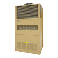
UNICOOL 28V1B5
AIRSYS UNICOOL 28V1B5 Manuals
Manuals and User Guides for AIRSYS UNICOOL 28V1B5. We have
2
AIRSYS UNICOOL 28V1B5 manuals available for free PDF download: Installation & Operation Manual, Installation And Operation Manual
AIRSYS UNICOOL 28V1B5 Installation & Operation Manual (121 pages)
Wall Mounted Packaged Air Conditioners
Brand:
AIRSYS
| Category:
Air Conditioner
| Size: 5.92 MB
Table of Contents
Table of Contents
3
Introduction
6
Using this Manual
7
Table 1-1 Packaging Symbols
8
Model Identification
9
Figure 1-1 Model Number
9
Acronyms and Abbreviations
10
Table 1-2 Acronyms and Abbreviations
10
Product Overview
11
Figure 2-1 Operating Modes (Top Supply)
12
Mechanical Cooling System
13
Figure 2-2 Operating Modes (Bottom Supply)
13
Adaptive Free Cooling
13
Free Cooling System
13
Soft Start
13
The Control System (ASMUC.6 Controller)
14
Ease of Control and Configuration
14
Synchronized Cooling
14
Standalone Mode
14
Heat Load Matching
14
Turbo Boost
15
Quiet Mode
15
Installation
16
Installation Preparation
17
Delivery
17
General Safety Rules
18
Warranty
18
Moving the Unit
18
Required Materials
19
AIRSYS Supplied Materials
19
Table 3-1 AIRSYS Provided Materials
19
Materials Supplied by Installer
20
Table 3-2 Installer Supplied Materials
20
Summary Electrical Ratings (Wire Sizing)
22
Table 3-3 WPU Electrical Ratings
22
Table 3-4 Controller Electrical Ratings
22
Table 3-6 Installation Clearances
23
Table 3-5 Dimensions and Weight by Model Number
23
Clearances
23
Select the Wall for Installing the Unit
23
Physical Installation
23
Pouring the Concrete Pad (B5 Cabinet Only)
24
Make Openings in the Wall
24
Table 3-7 Openings and Holes in the Wall (Bottom Supply)
24
Install Weather Stripping
25
Table 3-8 Openings and Holes in the Wall (Top Supply)
25
Figure 3-1 Install Weather Stripping
25
Position the Unit
26
Figure 3-2 Inclination of Mounted WPU
26
Figure 3-3 Position the Unit
26
Figure 3-5 Seal the Joints between Wpus and Wall
27
Figure 3-4 Remove Wooden Pallet
27
Seal the Joints between Wpus and Wall
27
Remove Wooden Pallet from WPU
27
Install the Support Stand (B5 Cabinet Only)
27
Attach the Supply Air Grill and the Return Air Grill to the Wall
28
Remove the Compressor Brackets
28
Figure 3-6 Install Supply and Return Air Grilles
28
Figure 3-7 Remove Compressor Brackets
28
Figure 3-8 Prefill Water to Drain Trap
29
Controller Box Installation
30
Install Outdoor Temperature Sensor
31
Table 3-9 Key Components in the Controller Box Assembly
31
Position the Humidity Sensor
32
Figure 3-9 Ensure no Leakage
32
Figure 3-10 Position the Indoor Temperature Sensor
33
Position Indoor Temperature Sensor
33
Cautions
33
Complete Electrical Connections
33
Output Alarms
34
Input Alarms
34
DC Fail-Over Input
35
Electrical Connection to Controller Box
35
Supplying Power to Wpus
37
Complete the Installation Checklist
38
System Commissioning
38
Turn on Component Breakers and Primary Power
38
Verify Proper Phase Connection (3 Phase Power Only)
38
Figure 3-11 Phase Monitor
39
Change System Units (Optional)
39
Set IP Addresses for Controller (Optional for Remote Monitoring)
39
Upgrade System Software
39
Remove the PGD from the Controller (if External Display Not Available)
40
Figure 3-12 IP Configuration
40
Set the Unit IP Addresses
41
Verify the Unit Model Number
41
Optional: Set the Unit Serial Number
41
Set the Number of Units and Zones
42
Zone Configuration (Optional)
42
Figure 3-13 Zone Configuration Screen
42
Match Unit ID with IP Address
43
Turn the HVAC System on
43
Figure 3-14 On/Off Screen
43
Execute the Step-Test
44
Set the System Clock
45
Verify Sensor Readings
45
Table 3-10 Step Test
45
Verify Indoor Setpoint
46
Verify Input and Output Alarms
46
Figure 3-15 Verify the Main Setpoint
46
Clearing Alarm History
47
Enable SNMP (Optional)
47
Complete the Registration Card
48
Figure 3-16 Enable SNMP
48
System Operation
51
Figure 4-1 PGD User Interface
52
Table 4-1 PGD Button Actions
52
User Interface Introduction
52
Figure 4-2 Main Screen
53
Navigating Menus
53
Main Screen
53
Table 4-2 System Statuses
54
Figure 4-3 On/Off Screen
54
Turning the System on and off
54
Changing the Setpoint and Free Cooling Humidity Limit
55
Using Comfort Mode
55
Figure 4-4 Setpoint Screen
55
Changing System Units
56
Viewing Controller Information
56
Figure 4-5 Comfort Mode Screen
56
Figure 4-6 Unit Selection Screen
56
Table 4-3 Controller Info Menu
57
Figure 4-7 HVAC ID Select Screen
58
Viewing Unit Information
58
Table 4-4 Unit Info Menu
58
Program Menus
60
Step Test
60
Figure 4-8 Program Menu Selection Screen
60
Table 4-5 Step Test
61
Figure 4-9 Step Test Selection Screen
61
Alarms
62
Table 4-6 Alarm Descriptions
62
Alarm History
63
Figure 4-10 Alarm Logs
64
Figure 4-11 Clear Alarm History
65
Exporting System History and Alarm Logs
65
Exporting System Logs
65
Clearing Alarm History
65
Exporting Alarm History
66
Resetting Factory Defaults
66
Figure 4-12 Hardware Configuration Menu
66
Set the Master
67
Figure 4-13 Factory Reset Screen
67
Operational Logic
68
Free Cooling (Economizer) Operation
68
Mechanical Cooling Operation
68
Figure 4-14 Set the Master
68
Figure 4-16 Dehumidification Logic
69
Figure 4-15 Heater Operation Logic
69
Generator Run
69
Emergency Ventilation
69
Heater Operation
69
Dehumidification
69
Sea-Side Mode
70
Afpd
70
Condenser Monitoring
70
System Parameters and Default Values
71
Step Test Menu Parameters
72
HVAC Config Menu Parameters
72
Table 5-1 Parameters in the Supply Fan Menu
72
Table 5-4 EU EEV Configuration Options
73
Table 5-2 Parameters in the Supply Fan Menu
73
Table 5-3 Parameters in the EEV Menu
73
Table 5-5 Carel EEV Configuration Options
74
Table 5-6 Parameters in the Compressor Menu
75
Table 5-7 Parameters in the Inverter Menu
75
Table 5-8 Additional Inverter Settings (EU)
76
Table 5-9 Additional Inverter Settings (Carel)
76
Table 5-10 Parameters in the Alarms Menu
78
Control Configuration Menu Parameters
79
Table 5-11 Parameters in the Network Menu
79
Table 5-12 Parameters in the Setpoints Menu
79
Table 5-13 Parameters in the Free Cooling Menu
80
Table 5-14 Parameters in the Sensors Menu
81
Accessing the Debug and Hardware Configuration Menus
82
Table 5-15 Parameters in the I/O Logic Menu
82
Table 5-16 Parameters in the System Menu
82
Accessing the System Menu
82
Table 5-17 Debug Menu Options
83
Table 5-18 Hardware Configuration Menu Options
83
Preventative Maintenance
84
General Operation Check
85
Check Main Voltage
85
Table 6-1 Preventative Maintenance Schedule
85
Replace Air Filter
86
Clean the Preliminary Air Filter
86
Perform the Step-Test
86
Check Wiring and Components
86
Inspect and Clean Condenser Coils
87
Inspect and Clean the Drain Pipes (both Evaporator and Condenser Drain Pipes)
87
Physical Inspection of the Damper
87
Operation Checklist
88
System Update
89
Local Software Update
90
Figure 7-1 Microusb Cable
90
Figure 7-2 Detaching Display
91
Figure 7-3 Controller Board
91
Figure 7-4 Upgrade Folder
91
Figure 7-5 Network Status
94
Required Equipment
94
Remote Software Upgrade
94
Figure 7-6 Master/Hvac Status
95
Figure 7-7 File Selection Screen
95
Figure 7-8 File Selection Screen
97
Figure 7-9 Network Status
98
Spare Parts
99
Table 8-1 Top Supply WPU Part Identification (T2/T3/T4)
100
Table 8-2 Bottom Supply WPU Part Identification (B2/B3/B4)
101
Table 8-3 Bottom Supply WPU Part Identification (B5)
102
Appendix A: Air Frame Drawing
103
Appendix B: Wiring Diagrams
104
Appendix C: Mechanical Drawings
110
Appendix D: Onsite Refrigerant Charging
116
List of Tables
118
Advertisement
AIRSYS UNICOOL 28V1B5 Installation And Operation Manual (112 pages)
Wall Packaged Unit Air Conditioners, ASMUC.6, ASMUC.6.AC, ASMUC.6.DC Controllers
Brand:
AIRSYS
| Category:
Air Conditioner
| Size: 5.88 MB
Table of Contents
Table of Contents
3
Chapter 1: Introduction
7
Using this Manual
8
Model Identification
9
Acronyms and Abbreviations
10
Chapter 2: Product Overview
11
Free Cooling System
12
Adaptive Free Cooling
12
Mechanical Cooling System
12
Soft Start
12
The Control System (ASMUC.6 Controller)
12
Ease of Control and Configuration
13
Synchronized Cooling
13
Standalone Mode
13
Heat Load Matching
13
Turbo Boost
13
Quiet Mode
13
Chapter 3: Installation
14
Installation Preparation
14
Delivery
14
Warranty
15
Moving the Unit
15
General Safety Rules
16
Required Materials
16
AIRSYS Supplied Materials
16
Materials Supplied by Installer
17
Electrical Ratings (Wire Sizing)
19
Physical Installation
20
Select the Wall for Installing the Unit
20
Clearances
20
Pouring the Concrete Pad (28V1B5 Only)
21
Make Openings in the Wall
21
Install Weather Stripping
23
Position the Unit
23
Remove Wooden Pallet from WPU
24
Install the Support Stand (28V1B5 Only)
24
Seal the Joints between Wpus and Wall
25
Attach the Supply Air Grill and the Return Air Grill to the Wall
25
Remove the Compressor Brackets
26
Controller Box Installation
27
Install Outdoor Temperature Sensor
28
Position the Humidity Sensor
30
Position the Indoor Temperature Sensor
30
Complete Electrical Connections
31
Cautions
31
Output Alarms
31
Input Alarms
32
Electrical Connection to Controller Box
33
Supplying Power to Wpus
34
Complete the Installation Checklist
35
System Commissioning
36
Turn on Component Breakers and Primary Power
36
Upgrade System Software (Optional)
36
Change System Units (Optional)
36
Set IP Addresses for Controller (Optional for Remote Monitoring)
37
Remove the PGD from the Controller (if External Display Not Available)
38
Set the Unit IP Addresses
38
Verify the Unit Model Number
39
Optional: Set the Unit Serial Number
39
Set the Number of Units and Zones
40
Zone Configuration (Optional)
40
Match Unit ID with IP Address
41
Turn the HVAC System on
41
Execute the Step-Test
42
Set the System Clock
43
Verify Sensor Readings
43
Verify Indoor Setpoint
43
Verify Input and Output Alarms
44
Clear the Alarm History
45
Enable SNMP (Optional)
45
Complete the Registration Card
46
Chapter 4: System Operation
51
User Interface Introduction
51
Navigating Menus
52
Main Screen
52
Turning the System on and off
53
Changing the Setpoint and Free Cooling Humidity Limit
54
Using Comfort Mode
55
Changing System Units
55
Viewing Controller Information
56
Viewing Unit Information
57
Program Menus
59
Step Test
60
Alarms
61
Alarm History
63
Clearing Alarm History
63
Exporting System History and Alarm Logs
64
Exporting System Logs
64
Exporting Alarm History
65
Resetting Factory Defaults
65
Set the Master
66
Operational Logic
67
Free Cooling (Economizer) Operation
67
Mechanical Cooling Operation
67
Heater Operation
67
Dehumidification
68
Generator Run
69
Emergency Ventilation
69
Seaside Mode
69
Afpd
69
Condenser Monitoring
69
Chapter 5: System Parameters and Default Values
70
Step Test Menu Parameters
70
Hvac Config Menu Parameters
70
Control Configuration Menu Parameters
77
System Menu Parameters
80
Debug and Hardware Configuration Menu Parameters
80
Chapter 6: Preventative Maintenance
82
General Operation Check
82
Check Main Voltage
82
Check Wiring and Components
83
Perform the Step-Test
83
Replace Air Filter
84
Clean the Preliminary Air Filter
84
Inspect and Clean Condenser Coils
84
Inspect and Clean the Drain Pipes (both Evaporator and Condenser Drain Pipes)
85
Physical Inspection of the Damper
85
Operations Checklist
86
Chapter 7: System Update
87
Local Software Update
87
Remote Software Upgrade
91
Chapter 8: Spare Parts
95
Appendix A: Air Frame Drawing
96
Appendix B: Wiring Diagrams
97
Appendix C: Mechanical Drawings
104
Advertisement
Related Products
AIRSYS UNICOOL 28V2B5
AIRSYS UNICOOL 11V1T3
AIRSYS UNICOOL 11V1B3
AIRSYS UNICOOL 15V1T4
AIRSYS UNICOOL 15V1B4
AIRSYS UniCool 7V1T2
AIRSYS UniCool 7V1B2
AIRSYS 13E1C3
AIRSYS 18E1C4
AIRSYS 3R1C1
AIRSYS Categories
Air Conditioner
Heat Pump
Cell Phone
More AIRSYS Manuals
Login
Sign In
OR
Sign in with Facebook
Sign in with Google
Upload manual
Upload from disk
Upload from URL