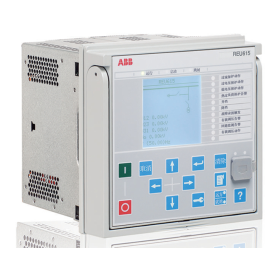
Sign In
Upload
Manuals
Brands
ABB Manuals
Relays
REU615
ABB REU615 Manuals
Manuals and User Guides for ABB REU615. We have
7
ABB REU615 manuals available for free PDF download: Manual, Applications Manual, Product Manual
ABB REU615 Manual (80 pages)
Modbus Point List
Brand:
ABB
| Category:
Control Unit
| Size: 3.4 MB
Table of Contents
Table of Contents
7
Section 1 Introduction
13
This Manual
13
Intended Audience
13
Product Documentation
13
Product Documentation Set
13
Document Revision History
14
Related Documentation
14
Symbols and Conventions
15
Symbols
15
Document Conventions
15
Functions, Codes and Symbols
16
Section 2 Modbus Data Mappings
19
Overview
19
Supported Functions
19
Point List for REU615 Ver.4.0 UE01-02
21
Indications
21
Commondata1
21
LD0.LEDPTRC1 Global Conditioning
22
LD0.TRPPTRC1 Protection Trip Conditioning (1)
22
LD0.TRPPTRC2 Protection Trip Conditioning (2)
22
LD0.CMMXU1 Phase Current Limit Supervision (1)
22
LD0.RESVMMXU1 Residual Voltage Limit Supervision (1)
23
LD0.LEDGGIO1 Indication LED States
23
LD0.TCSSCBR1 Trip Circuit Supervision (1)
23
LD0.TCSSCBR2 Trip Circuit Supervision (2)
24
LD0.VMMXU1 Phase Voltage Limit Supervision (1)
24
CTRL.DCSXSWI1 Disconnector 1 Mom Position
24
CTRL.DCSXSWI2 Disconnector 2 Mom Position
24
CTRL.DCSXSWI3 Disconnector 3 Mom Position
25
CTRL.ESSXSWI1 Earth Switch 1 Mom Position
25
CTRL.CBCSWI1 Circuit Breaker 1 Mom Position
25
CTRL.ESSXSWI2 Earth Switch 2 Mom Position
25
CTRL.CBCSWI1 Circuit Breaker 1 Mom+MCD Position
26
CTRL.CBCILO1 Circuit Breaker 1 Enable Signals
26
CTRL.CBXCBR1 Circuit Breaker 1 Blocking Signals
26
LD0.LEDPTRC1 Global Conditioning - Phase Information
27
LD0.PHLPTOC1 Phase Overcurrent Protection, Low Stage (1)
27
LD0.PHHPTOC1 Phase Overcurrent Protection, High Stage (1)
28
LD0.PHIPTOC1 Phase Overcurrent Protection, Instantaneous Stage (1)
28
LD0.T2PTTR1 Thermal Overload Protection (1)
28
LD0.ARCSARC1 Fault Arc Protection, Stage 1
29
LD0.ARCSARC2 Fault Arc Protection, Stage 2
29
LD0.ARCSARC3 Fault Arc Protection, Stage 3
29
LD0.SEQRFUF1 Fuse Failure Protection
30
CTRL.CCRDIF1 Current Circuit Failure Detection
30
LD0.PHPTOV1 Phase Overvoltage Protection (1)
30
LD0.PHPTOV2 Phase Overvoltage Protection (2)
31
LD0.PHPTOV3 Phase Overvoltage Protection (3)
31
LD0.PSPTUV1 Positive-Sequence Undervoltage Protection (1)
31
LD0.PSPTUV2 Positive-Sequence Undervoltage Protection (2)
32
LD0.NSPTOV1 Negative-Sequence Overvoltage Protection (1)
32
LD0.NSPTOV2 Negative-Sequence Overvoltage Protection (2)
33
LD0.PHPTUV1 Phase Undervoltage Protection (1)
33
LD0.PHPTUV2 Phase Undervoltage Protection (2)
33
LD0.PHPTUV3 Phase Undervoltage Protection (3)
34
LD0.ROVPTOV1 Residual Overvoltage Protection (1)
34
LD0.ROVPTOV2 Residual Overvoltage Protection (2)
35
LD0.ROVPTOV3 Residual Overvoltage Protection (3)
35
LD0.SECRSYN1 Synchrocheck (1)
35
LD0.OLATCC1 On-Load Tap Changer Controller
35
LD0.FRPFRQ1 Frequency Protection (1)
36
LD0.FRPFRQ2 Frequency Protection (2)
37
LD0.FRPFRQ3 Frequency Protection (3)
37
LD0.FRPFRQ4 Frequency Protection (4)
38
LD0.FRPFRQ5 Frequency Protection (5)
38
LD0.FRPFRQ6 Frequency Protection (6)
39
LD0.LSHDPFRQ1 Load Shedding - Instance 1
39
LD0.LSHDPFRQ2 Load Shedding - Instance 2
39
LD0.LSHDPFRQ3 Load Shedding - Instance 3
40
LD0.LSHDPFRQ4 Load Shedding - Instance 4
40
LD0.LSHDPFRQ5 Load Shedding - Instance 5
41
LD0.MAPGAPC1 Multipurpose Analog Protection Function (1)
41
LD0.MAPGAPC2 Multipurpose Analog Protection Function (2)
41
LD0.MAPGAPC3 Multipurpose Analog Protection Function (3)
42
LD0.MAPGAPC4 Multipurpose Analog Protection Function (4)
42
LD0.MAPGAPC5 Multipurpose Analog Protection Function (5)
42
LD0.MAPGAPC6 Multipurpose Analog Protection Function (6)
42
LD0.XGGIO130 Physical I/O States (BIO Card X130)
43
CTRL.DCXSWI1 Controllable Discon. 1 Mom Position Data
43
CTRL.DCXSWI2 Controllable Discon. 2 Mom Position Data
44
CTRL.ESXSWI1 Controllable Earth Switch 1 Mom Position
44
LD0.XGGIO130 Physical I/O States (BIO Card X130)
45
LD0.XGGIO110 Physical I/O States (BIO Card X110)
45
LD0.XGGIO100 Physical I/O States (PSM Card X100)
46
LD0.XAGGIO130 Physical I/O States (AIM Card XA130)
47
LD0.MVGAPC1 Multipurpose Binary Inputs (1)
47
LD0.MVGAPC2 Multipurpose Binary Inputs (2)
48
LD0.SPCGGIO2 Multipurpose Binary Output States (2)
48
Registers
49
User Definable Registers [Alt.1], Visible on 3X and 4X
50
User Definable Bits [Alt.2], Visible on 0X,1X,3X and 4X
50
SSR1 System Status Register 1 - Device Health
50
SSR2 System Status Register 2 - IED Mode and State
51
SSR3 System Status Register 3 - Data Available 1 (Client-Dependent)
52
SSR4 System Status Register 4 - Data Available 2 (Client-Dependent - User-Definable)
52
SSR5 System Status Register 5 - Device Alive Register
53
SSR6 System Status Register 6 - Control Command Status (Client-Dependent)
53
LD0.CMMXU1 Phase Current Measurements (1)
54
LD0.RESVMMXU1 Residual Voltage Measurement (1)
54
LD0.CMSQI1 Sequence of Current Measurements (1)
54
LD0.T2PTTR1 Thermal Protection Values (2)
54
LD0.VMMXU1 Voltage Measurements (1)
55
LD0.VMSQI1 Sequence of Voltage Measurements (1)
55
LD0.PEMMXU1 Three-Phase Power Measurements
55
LD0.TPOSSLTC1 Tap Changer Position
56
LD0.FMMXU1 Frequency Measurement
56
LD0.SECRSYN1 Synchrocheck
56
Indication Bits Mirrored in Registers
56
LD0.PEMSTA1 Power Measurement Demand Values (1)
56
LD0.VMSTA1 Voltage Demand Values (1)
57
LD0.RESVMSTA1 Residual Voltage Demand Value (1)
58
LD0.CMSTA1 Phase Current Demand Values (1)
58
CTRL.CBCSWI1 Circuit Breaker Operation Counter (1)
59
Ld0.Arcsarcx1 Fault Arc Counters
59
LD0.XRGGIO130 RTD Input Values
60
LD0.PEMMTR1 Three-Phase Energy Measurements
60
System Diagnostic Values
61
LD0.OLATCC1 Tap Changer Control and Status
61
Control Structure 1
61
Control Structure 2
62
Control Structure 3
62
Control Structure 4
62
Control Structure 5
62
Control Structure 6
63
Control Structure 7
63
Control Structure 8
63
Device ID String
63
IED Real-Time Clock (in Local Time Mode) - Read and Write (Synchronize)
64
IED Real-Time Clock (in UTC Time Mode) - Read and Write (Synchronize)
64
Time and Reason for Latest IED Reset
64
Active Parameter Setting Group - Read and Write
65
Event Record Structure
65
Fault Record Structure Header
69
Fault Record Data
70
Controls
71
CTRL.CBCSWI1 Circuit Breaker (1) Control
71
Reset, Acknowledge and Trigger Points (B)
71
LD0.LPHD1 IED Warm Reset
72
LD0.LSHDPTRC1 Load Shedding (1) Controls
72
LD0.LSHDPTRC2 Load Shedding (2) Controls
72
LD0.LSHDPTRC3 Load Shedding (3) Controls
73
LD0.LSHDPTRC4 Load Shedding (4) Controls
73
LD0.LSHDPTRC5 Load Shedding (5) Controls
73
LD0.SRGAPC1 Reset SRGAPC1 Generic Flip-Flops
73
LD0.SRGAPC2 Reset SRGAPC2 Generic Flip-Flops
74
LD0.SPCGGIO1 Multipurpose Binary Outputs (1)
74
LD0.SPCGGIO2 Multipurpose Binary Outputs (2)
75
CTRL.DCCSWI1 Disconnector (1) Control
75
CTRL.DCCSWI2 Disconnector (2) Control
76
CTRL.ESCSWI1 Earth Switch (1) Control
76
Section 3 Glossary
77
Advertisement
ABB REU615 Manual (64 pages)
Brand:
ABB
| Category:
Surge Protector
| Size: 2.57 MB
Table of Contents
Table of Contents
7
Section 1 Introduction
13
This Manual
13
Intended Audience
13
Product Documentation
13
Product Documentation Set
13
Document Revision History
14
Related Documentation
14
Symbols and Conventions
15
Symbols
15
Document Conventions
15
Functions, Codes and Symbols
16
Section 2 DNP3 Data Mappings
19
Overview
19
Supported Functions
19
Binary Inputs
21
System Functions
21
CTRL.LLN0 Local/Remote State (also Present in DNP IIN-Bits)
21
LD0.LLN0 Settings Supervision
22
Switchgear Functions
22
Ctrl.cxxxxx1 Circuit Breaker (1) CB Object and Failure Protection
22
Ctrl.dxxxxx1 Controllable Disconnector (1)
22
Ctrl.dxxxxx2 Controllable Disconnector (2)
23
Ctrl.exxxxx1 Controllable Earth Switch (1)
23
Sensors and Monitoring Functions
23
LD0.ARCSARC1 Fault Arc Protection Stage 1
23
LD0.ARCSARC2 Fault Arc Protection Stage 2
24
LD0.ARCSARC3 Fault Arc Protection Stage 3
24
LD0.TCSSCBR1 Trip Circuit Supervision (1)
24
LD0.TCSSCBR2 Trip Circuit Supervision (2)
24
Automatic Control Functions
25
LD0.OLATCC1 On-Load Tap Changer Controller
25
Metering and Measurand Functions
25
LD0.CMMXU1 Phase Currents (1) Limit Supervision
25
LD0.RESCMMXU1 Residual Current Limit Supervision
25
LD0.VMMXU1 Three-Phase Voltage Limit Supervision
26
LD0.RESVMMXU1 Residual Voltage Limit Supervision
26
Protection Functions
26
LD0.LEDPTRC1 Global Protection Signals
26
LD0.TRPPTRC1 Global Conditioning (1)
26
LD0.TRPPTRC2 Global Conditioning (2)
27
LD0.FRPFRQ1 Frequency Protection (1)
27
LD0.FRPFRQ2 Frequency Protection (2)
27
LD0.FRPFRQ3 Frequency Protection (3)
27
LD0.FRPFRQ4 Frequency Protection (4)
28
LD0.FRPFRQ5 Frequency Protection (5)
28
LD0.FRPFRQ6 Frequency Protection (6)
28
LD0.LSHDPFRQ1 Load-Shedding - Instance 1
29
LD0.LSHDPFRQ2 Load-Shedding - Instance 2
29
LD0.LSHDPFRQ3 Load-Shedding - Instance 3
29
LD0.LSHDPFRQ4 Load-Shedding - Instance 4
30
LD0.LSHDPFRQ5 Load-Shedding - Instance 5
30
LD0.NSPTOV1 Negative-Sequence Overvoltage Protection - Stage 1
30
LD0.NSPTOV2 Negative-Sequence Overvoltage Protection - Stage 2
30
LD0.PHHPTOC1 Phase Overcurrent Protection - High Stage 1
31
LD0.PHIPTOC1 Phase Overcurrent Protection - Instantaneous Stage 1
31
LD0.PHLPTOC1 Phase Overcurrent Protection - Low Stage 1
31
LD0.PHPTOV1 Phase Overvoltage Protection - Stage 1
31
LD0.PHPTOV2 Phase Overvoltage Protection - Stage 2
31
LD0.PHPTOV3 Phase Overvoltage Protection - Stage 3
32
LD0.PHPTUV1 Phase Undervoltage Protection - Stage 1
32
LD0.PHPTUV2 Phase Undervoltage Protection - Stage 2
32
LD0.PHPTUV3 Phase Undervoltage Protection - Stage 3
32
LD0.PSPTUV1 Positive-Sequence Undervoltage Protection - Stage 1
32
LD0.PSPTUV2 Positive-Sequence Undervoltage Protection - Stage 2
33
LD0.ROVPTOV1 Residual Overvoltage Protection (1)
33
LD0.ROVPTOV2 Residual Overvoltage Protection (2)
33
LD0.ROVPTOV3 Residual Overvoltage Protection (3)
33
LD0.T2PTTR1 Thermal Protection (2)
33
Protection-Related Functions
34
LD0.CCRDIF1 Current Circuit Failure Protection
34
LD0.SEQRFUF1 Fuse Failure Protection
34
DR.RDRE1 Disturbance Recorder
34
LD0.SECRSYN1 Synchrocheck
34
Generic Functions
35
LD0.MAPGAPC1 Multipurpose Analog Protection Function (1)
35
LD0.MAPGAPC2 Multipurpose Analog Protection Function (2)
35
LD0.MAPGAPC3 Multipurpose Analog Protection Function (3)
35
LD0.MAPGAPC4 Multipurpose Analog Protection Function (4)
35
LD0.MAPGAPC5 Multipurpose Analog Protection Function (5)
35
LD0.MAPGAPC6 Multipurpose Analog Protection Function (6)
36
LD0.MVGAPC1 Multipurpose Binary Inputs (1)
36
LD0.MVGAPC2 Multipurpose Binary Inputs (2)
36
LD0.SPCGGIO2 Multipurpose Binary Outputs - Status (2)
37
Physical and Raw I/O Data
37
LD0.XRGGIO130 Alarm/Warning
37
LD0.XAGGIO130 Physical I/O
37
LD0.XGGIO100 Physical I/O
38
LD0.XGGIO110 Physical I/O
38
LD0.XGGIO130 Physical I/O
38
Binary Outputs
39
System Functions
39
LD0.LLN0/LPHD1 Reset Indications and Leds, Reset Device
39
LD0.DNPGGIO1 Parameter Setting Group Control
39
Switchgear Functions
40
CTRL.CBCSWI1 Circuit Breaker Control
40
CTRL.DCCSWI1 Controllable Disconnector (1) Control
40
CTRL.DCCSWI2 Controllable Disconnector (2) Control
40
CTRL.ESCSWI2 Controllable Earth Switch (2) Control
40
Metering and Measurand Functions
41
LD0.PEMMXU1 Reset Accumulated Energy Values
41
Protection Functions
41
LD0.LSHDPFRQ1 Loadshedding Controls (1)
41
LD0.LSHDPFRQ2 Loadshedding Controls (2)
41
LD0.LSHDPFRQ3 Loadshedding Controls (3)
41
LD0.LSHDPFRQ4 Load Shedding Controls (4)
42
LD0.LSHDPFRQ5 Load Shedding Controls (5)
42
Protection-Related Functions
42
DR.RDRE1 Disturbance Recorder
42
Generic Functions
42
LD0.SPCGGIO1 Multipurpose Binary Outputs (1)
42
LD0.SPCGGIO2 Multipurpose Binary Outputs (2)
43
LD0.SRGAPC1 Multipurpose Binary Outputs - Flip-Flop Resets (1)
44
LD0.SRGAPC2 Multipurpose Binary Outputs - Flip-Flop Resets (2)
44
Analog Inputs
44
System Functions
45
CTRL.LLN0 Local Remote Station off
45
LD0.LPHD1 System Values
45
LD0.DNPGGIO1 Active Parameter Setting Group
45
LD0.LEDGGIO1 LHMI LED Indications (3 States)
46
Switchgear Functions
46
CTRL.CBCSWI1 CB 4-Pole (2 Bit) Position Value
46
CTRL.DCSXSWI1 Disconnector 1, 4-Pole (2 Bit) Position Values
46
CTRL.DCSXSWI2 Disconnector 2, 4-Pole (2 Bit) Position Values
47
CTRL.DCSXSWI3 Disconnector 3, 4-Pole (2 Bit) Position Values
47
CTRL.DCXSWI1 Controllable Disconnector 1, 4-Pole (2 Bit) Position Values
47
CTRL.DCXSWI2 Controllable Disconnector 2, 4-Pole (2 Bit) Position Values
47
CTRL.ESSXSWI1 Earth Switch 1, 4-Pole (2 Bit) Position Values
47
CTRL.ESSXSWI2 Earth Switch 2, 4-Pole (2 Bit) Position Values
48
CTRL.ESXSWI1 Controllable Earth Switch 1, 4-Pole (2 Bit) Position Values
48
Sensors and Monitoring Functions
48
LD0.TPOSSLTC1 Tap Changer Position Value
48
Automatic Control Functions
48
LD0.OLATCC1 On-Load Tap Changer Controller
48
Metering and Measurand Functions
49
LD0.CMMXU1 Phase Currents (1)
49
LD0.RESCMMXU1 Residual Current (1)
49
LD0.CSMSQI1 Sequence of Currents
49
LD0.VMMXU1 Voltage Measurement
49
LD0.RESVMMXU1 Residual Voltage (1)
50
LD0.VSMSQI1 Sequence of Voltage Measurement
50
LD0.PEMMTR1 Power Measurement and Accumulated Power Values
50
LD0.FMMXU1 Frequency Measurement
51
Protection Functions
51
LD0.T2PTTR1 Temperature Protection Values (2)
51
Protection-Related Functions
51
DR.RDRE1 Disturbance Recorder Values
51
LD0.SECRSYN1 Synchrocheck Line and Bus State
51
Generic Functions
52
LD0.XRGGIO130 RTD Inputs
52
Section 3 DNP3 Protocol Implementation
53
DNP3 Device Profile
53
DNP3 Implementation Table
55
Section 4 Glossary
59
ABB REU615 Manual (56 pages)
Brand:
ABB
| Category:
Industrial Equipment
| Size: 2.86 MB
Table of Contents
Table of Contents
7
Section 1 Introduction
11
This Manual
11
Intended Audience
11
Product Documentation
11
Product Documentation Set
11
Document Revision History
12
Related Documentation
12
Symbols and Conventions
13
Symbols
13
Document Conventions
13
Functions, Codes and Symbols
14
Section 2 IEC 60870-5-103 Data Mappings
17
Overview
17
Supported Functions
17
Indications and Controls
19
General Data(FUN=0) IEC 60870-5-103 Standard
19
General Data(FUN=10) - 615-Specific
20
LD0.MVGAPC1 Multipurpose Binary Inputs (1)
21
LD0.MVGAPC2 Multipurpose Binary Inputs (2)
21
LD0.SRGAPC1 Multipurpose Binary Outputs - Flip-Flop Resets (1)
21
LD0.SRGAPC2 Multipurpose Binary Outputs - Flip-Flop Resets (2)
22
LD0.SPCGGIO1 Multipurpose Binary Outputs (1)
22
LD0.SPCGGIO2 Multipurpose Binary Outputs (2)
23
LD0.SEQRFUF1 Fuse Failure Protection
23
CTRL.CCRDIF1 Current Circuit Failure Protection
24
LD0.TPOSSLTC1 Tap Position
24
LD0.SECRSYN1 Synchrocheck Indications
24
LD0.FRPFRQ1 Frequency Protection (1)
24
LD0.FRPFRQ2 Frequency Protection (2)
25
LD0.FRPFRQ3 Frequency Protection (3)
25
LD0.FRPFRQ4 Frequency Protection (4)
25
LD0.FRPFRQ5 Frequency Protection (5)
26
LD0.FRPFRQ6 Frequency Protection (6)
26
LD0.MAPGAPC1 Multipurpose Analog Protection Function (1)
26
LD0.MAPGAPC2 Multipurpose Analog Protection Function (2)
27
LD0.MAPGAPC3 Multipurpose Analog Protection Function (3)
27
LD0.MAPGAPC4 Multipurpose Analog Protection Function (4)
27
LD0.MAPGAPC5 Multipurpose Analog Protection Function (5)
27
LD0.MAPGAPC6 Multipurpose Analog Protection Function (6)
28
LD0.XRGGIO130 Alarm and Warning
28
LD0.PHPTOV3 Phase Overvoltage Protection - Stage 3
28
LD0.PHPTOV2 Phase Overvoltage Protection - Stage 2
28
LD0.PHPTOV1 Phase Overvoltage Protection - Stage 1
29
LD0.PHPTUV3 Phase Undervoltage Protection - Stage 3
29
LD0.PHPTUV2 Phase Undervoltage Protection - Stage 2
29
LD0.PHPTUV1 Phase Undervoltage Protection - Stage 1
30
LD0.PSPTUV2 Positive-Sequence Undervoltage Protection - Stage 2
30
LD0.PSPTUV1 Positive-Sequence Undervoltage Protection - Stage 1
30
LD0.NSPTOV2 Negative-Sequence Overvoltage Protection - Stage 2
30
LD0.NSPTOV1 Negative-Sequence Overvoltage Protection - Stage 1
31
LD0.ROVPTOV1 Residual Overvoltage Protection - Stage 1
31
LD0.ROVPTOV2 Residual Overvoltage Protection - Stage 2
31
LD0.ROVPTOV3 Residual Overvoltage Protection - Stage 3
31
LD0.XGGIO130 Physical Binary I/O Signals (Status Only)
32
LD0.XGGIO120 Physical Binary I/O Signals (Status Only)
32
LD0.XGGIO110 Physical Binary I/O Signals (Status Only)
32
LD0.XGGIO100 Physical Binary I/O Signals (Status Only)
33
LD0.OLATCC1 On-Load Tap Changer Controller
33
LD0.LSHDPFRQ1 Load Shedding - Instance 1
34
LD0.LSHDPFRQ2 Load Shedding - Instance 2
34
LD0.LSHDPFRQ3 Load Shedding - Instance 3
34
LD0.LSHDPFRQ4 Load Shedding - Instance 4
35
LD0.LSHDPFRQ5 Load Shedding - Instance 5
35
LD0.ARCSARC1 Fault Arc Protection - Stage 1
35
LD0.ARCSARC2 Fault Arc Protection - Stage 2
36
LD0.ARCSARC3 Fault Arc Protection - Stage 3
36
LD0.PHIPTOC1 Phase Overcurrent Protection
36
Instantaneous Stage 1
36
LD0.PHHPTOC1 Phase Overcurrent Protection - High Stage
36
LD0.PHLPTOC1 Phase Overcurrent Protection - Low Stage 1
37
LD0.T2PTTR1 Thermal Overload Protection (2)
37
LD0.CMMXU1 Phase Currents (1) Limit Supervision
37
LD0.VMMXU1 Phase Voltage (1) Limit Supervision
38
LD0.RESVMMXU1 Residual Voltage (1) Limit Supervision
38
Ctrl.cxxxxx1 Circuit Breaker (1) CB Object and Failure Protection
38
CTRL.DCXSWI1 Disconnector (1) - Controllable Object
39
CTRL.DCXSWI2 Disconnector (2) - Controllable Object
39
CTRL.ESXSWI1 Earth Switch - Controllable Object
39
CTRL.DCSXSWI1 Disconnector (1) - Non-Controllable Object
40
CTRL.DCSXSWI2 Disconnector (2) - Non-Controllable Object
40
CTRL.DCSXSWI3 Disconnector (3) - Non-Controllable Object
40
CTRL.ESSXSWI1 Earth Switch (1) - Non-Controllable Object
40
CTRL.ESSXSWI2 Earth Switch (2) - Non-Controllable Object
40
LD0.LEDGGIO1 LHMI LED Indications Type 1 (2 States)
41
LD0.LEDGGIO1 LHMI LED Indications Type 2 (3 States)
41
Class 2 Data Measurands
41
Class 2 Private Measurand Data (6 and 7)
43
Section 3 Interoperability Profile for 615 Series IEC 60870-5-103
45
Physical Layer
45
Electrical Interface
45
Optical Interface
45
Transmission Speed
45
Link Layer
45
Application Layer
46
Transmission Mode for Application Data
46
COMMON ADDRESS of ASDU
46
Selection of Standard Information Numbers in Monitor Direction
46
System Functions in Monitor Directions
46
Status Indications in Monitor Direction
46
Supervision Indications in Monitor Direction
47
Earth Fault Indications in Monitor Direction
47
Fault Indications in Monitor Direction
47
Auto-Reclosure Indications in Monitor Direction
48
Measurands in Monitor Direction
49
Generic Functions in Monitor Direction
49
Selection of Standard Information Numbers in Control Direction
49
System Functions in Control Direction
49
Basic Application Functions
50
Miscellaneous
50
Section 4 Glossary
51
Advertisement
ABB REU615 Product Manual (61 pages)
Relion 615 series Voltage Protection and Control
Brand:
ABB
| Category:
Relays
| Size: 6.24 MB
Table of Contents
Table of Contents
2
Description
3
Standard Configurations
3
Supported Functions
4
Standard Configuration a
6
Standard Configuration B
6
Protection Functions
6
Protection Function Overview of Standard Configuration a
7
Protection Function Overview of Standard Configuration B
8
Application
8
Supported ABB Solutions
10
Control
12
Measurement
12
Disturbance Recorder
13
Event Log
13
Recorded Data
13
Condition Monitoring
13
Trip-Circuit Supervision
13
Self-Supervision
13
Fuse Failure Supervision
13
Input/Output Overview
14
Current Circuit Supervision
14
Access Control
14
Inputs and Outputs
14
Station Communication
15
Self-Healing Ethernet Ring Solution
16
Supported Station Communication Interfaces and Protocols
17
Dimensions
18
Power Supply
18
Technical Data
18
Energizing Inputs
19
Binary Inputs
19
Rtd/Ma Measurement (XRGGIO130)
20
Signal Output X100: SO1
20
Signal Outputs and IRF Output
21
Double-Pole Power Output Relays with TCS Function
21
Single-Pole Power Output Relays
21
Front Port Ethernet Interfaces
21
Degree of Protection of Flush-Mounted IED
22
Station Communication Link, Fibre-Optic
22
Lens Sensor and Optical Fibre for Arc Protection
22
Irig-B
22
Environmental Tests
23
Electromagnetic Compatibility Tests
24
Insulation Tests
25
Mechanical Tests
25
Product Safety
26
EMC Compliance
26
Rohs Compliance
26
Three-Phase Non-Directional Overcurrent Protection (Phxptoc)
27
Three-Phase Overvoltage Protection (PHPTOV)
28
Three-Phase Overvoltage Protection (PHPTOV) Main Settings
29
Three-Phase Undervoltage Protection (PHPTUV) Main Settings
29
Three Phase Undervoltage Protection (PHPTUV)
29
Positive-Sequence Undervoltage Protection (PSPTUV)
30
Negative-Sequence Overvoltage Protection (NSPTOV)
30
Positive-Sequence Undervoltage Protection (PSPTUV) Main Settings
30
Negative-Sequence Overvoltage Protection (NSPTOV) Main Settings
31
Frequency Protection (FRPFRQ)
31
Frequency Protection (FRPFRQ) Main Settings
31
Thermal Overload Protection, Two Time Constants (T2PTTR)
32
Residual Overvoltage Protection (ROVPTOV)
32
Multipurpose Protection (MAPGAPC)
33
Residual Overvoltage Protection (ROVPTOV) Main Settings
33
Arc Protection (ARCSARC)
33
Arc Protection (ARCSARC) Main Settings
33
Load Shedding (LSHDPFRQ)
34
Load Shedding (LSHDPFRQ) Main Settings
34
Operation Characteristics
35
Control Functions
36
Synchrocheck (SECRSYN)
36
Synchronism and Energizing Check (SECRSYN) Main Settings
37
Tap Changer Control with Voltage Regulator (OLATCC)
38
Three-Phase Voltage Measurement (VMMXU)
40
Current Sequence Components (CSMSQI)
40
Three-Phase Current Measurement (CMMXU)
40
Measurement Functions
40
Three-Phase Power and Energy (PEMMXU)
41
Frequency Measurement (FMMXU)
41
Supervision Functions
42
Current Circuit Supervision (CCRDIF)
42
Current Circuit Supervision (CCRDIF) Main Settings
42
Fuse Failure Supervision (SEQRFUF)
42
Small Display
43
Large Display
43
Local HMI
43
Semi-Flush Mounting
44
Flush Mounting
44
Mounting Methods
44
IED Case and IED Plug-In Unit
45
Selection and Ordering Data
45
Accessories and Ordering Data
48
Tools
49
26. Terminal Diagrams
51
Terminal Diagram of Standard Configuration a
51
Terminal Diagram of Standard Configuration B
52
References
53
REU615 Functions, Codes and Symbols
54
Functions, Codes and Symbols
54
Document Revision History
56
ABB REU615 Applications Manual (80 pages)
Voltage Protection and Control
Brand:
ABB
| Category:
Surge Protector
| Size: 4.27 MB
Table of Contents
Table of Contents
7
Section 1 Introduction
9
This Manual
9
Intended Audience
9
Product Documentation
10
Product Documentation Set
10
Document Revision History
11
Related Documentation
12
Symbols and Conventions
12
Safety Indication Symbols
12
Manual Conventions
13
Functions, Codes and Symbols
13
Section 2 REU615 Overview
17
Overview
17
Product Version History
17
PCM600 and IED Connectivity Package Version
17
Operation Functionality
18
Optional Functions
18
Physical Hardware
18
Local HMI
20
Lcd
20
Leds
21
Keypad
21
Web HMI
22
Authorization
23
Communication
24
Section 3 REU615 Standard Configurations
27
Standard Configurations
27
Connection Diagrams
30
Presentation of Standard Configurations
33
Standard Configuration a
34
Applications
34
Functions
35
Default I/O Connections
36
Default Disturbance Recorder Settings
37
Functional Diagrams
38
Functional Diagrams for Protection
38
Functional Diagram for Disturbance Recorder
44
Functional Diagrams for Control and Interlocking
46
Standard Configuration B
49
Applications
49
Functions
50
Default I/O Connections
51
Default Disturbance Recorder Settings
53
Functional Diagrams
53
Functional Diagrams for Protection
54
Functional Diagrams for Disturbance Recorder and Supervision Functions
57
Functional Diagrams for Control and Interlocking
59
Section 4 Requirements for Measurement Transformers
65
Current Transformers
65
Current Transformer Requirements for Non-Directional Overcurrent Protection
65
Current Transformer Accuracy Class and Accuracy Limit Factor
65
Non-Directional Overcurrent Protection
66
Example for Non-Directional Overcurrent Protection
67
Section 5 IED Physical Connections
69
Inputs
69
Energizing Inputs
69
Phase Currents
69
Phase Voltages
69
Residual Current
69
Residual Voltage
70
Rtd/Ma Inputs
70
Auxiliary Supply Voltage Input
71
Binary Inputs
71
Outputs
72
Outputs for Tripping and Controlling
72
Outputs for Signalling
73
Irf
74
Section 6 Glossary
75
ABB REU615 Product Manual (56 pages)
Voltage Protection and Control
Brand:
ABB
| Category:
Controller
| Size: 4.97 MB
Table of Contents
Table of Contents
2
Description
3
Standard Configurations
3
Protection Functions
7
Application
7
Supported ABB Solutions
9
Control
11
Measurements
12
Disturbance Recorder
12
Event Log
12
Recorded Data
12
Condition Monitoring
13
Trip-Circuit Supervision
13
Self-Supervision
13
Fuse Failure Supervision
14
Current Circuit Supervision
14
Access Control
14
Inputs and Outputs
14
Station Communication
15
Technical Data
20
Local HMI
42
Mounting Methods
43
Relay Case and Plug-In Unit
43
Selection and Ordering Data
43
Accessories and Ordering Data
44
Tools
45
Cyber Security
46
Terminal Diagrams
47
Certificates
49
References
49
Functions, Codes and Symbols
50
Document Revision History
53
ABB REU615 Manual (40 pages)
Voltage Protection and Control
Brand:
ABB
| Category:
Industrial Equipment
| Size: 1.84 MB
Table of Contents
Table of Contents
7
Section 1 Introduction
9
This Manual
9
Intended Audience
9
Product Documentation
10
Product Documentation Set
10
Document Revision History
11
Related Documentation
12
Symbols and Conventions
12
Safety Indication Symbols
12
Manual Conventions
12
Functions, Codes and Symbols
13
Section 2 DNP3 Data Mappings
17
Overview
17
Point List for REU615 Ver.3.0 UE01-02
18
Section 3 DNP3 Protocol Implementation
31
DNP3 Device Profile
31
DNP3 Implementation Table
33
Section 4 Glossary
37
Advertisement
Related Products
ABB REU 610
ABB REU615 B
ABB REU615 A
ABB REU 523
ABB REU 513
ABB Relion REB500
ABB RED615 B
ABB RED615 C
ABB REF615 L
ABB REX 521
ABB Categories
Industrial Equipment
Controller
Measuring Instruments
Battery Charger
DC Drives
More ABB Manuals
Login
Sign In
OR
Sign in with Facebook
Sign in with Google
Upload manual
Upload from disk
Upload from URL