Sign In
Upload
Manuals
Brands
ABB Manuals
Relays
REX 521
ABB REX 521 Manuals
Manuals and User Guides for ABB REX 521. We have
7
ABB REX 521 manuals available for free PDF download: Technical Reference Manual, Standard Configurations, Technical Reference Manual, General, Operator's Manual, Operating Manual
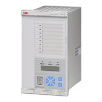
ABB REX 521 Technical Reference Manual, Standard Configurations (250 pages)
Protection Relay
Brand:
ABB
| Category:
Protection Device
| Size: 4.24 MB
Table of Contents
Table of Contents
3
1 About this Manual
13
Copyrights
13
Trademarks
13
General
13
Abbreviations
14
Related Documents
14
Document Revisions
15
Safety Information
16
2 Introduction
17
3 Standard Configurations
23
HW Version: Basic
23
Standard Configuration B01
23
Features
23
Application
24
Standard Configuration B02
26
Features
26
Application
27
HW Version: Medium
29
Standard Configuration M01
29
Features
29
Application
30
Standard Configuration M02
32
Features
32
Application
33
HW Version: High/Sensor
35
Standard Configuration H01 (Sensor)
35
Features
35
Application
36
Standard Configuration H02
38
Features
38
Application
39
Standard Configuration H03
41
Features
41
Application
42
Standard Configuration H04
44
Features
44
Application
45
Standard Configuration H05
47
Features
47
Application
48
Standard Configuration H06
50
Features
50
Application
51
Standard Configuration H07
53
Features
53
Application
54
Standard Configuration H08 (no Sensors)
56
Features
56
Application
57
Standard Configuration H09 (no Sensors)
59
Features
59
Application
60
4 Reading of the Overview Diagrams of the Signal Routings
63
Digital Inputs
63
Input Selectors
64
Input Switchgroups (SWGRP)
65
Input Signals
66
Function Blocks in the Overview Diagrams of the Signal Routings
67
Function Blocks
67
Output Switchgroups (SWGRP)
68
Output Selectors
68
Other Functions Described in Signal Overview Diagrams
69
Lockout Function
69
5 Parametrization of the Digital Inputs
73
Selectors
73
Reset
73
Group
73
Blocking
73
Disturbance Recorder Trigger
73
Power Quality Trigger
74
Master Trip
74
External Trip
74
Lockout Reset
74
Local/Remote
74
Close Enable
74
Direct Control (Open/Close)
74
Object Indication
74
Time Synchronization
75
AR Inhibit, AR on Input, Start AR
75
BACTRL (Basic Angle Control)
75
Logic Input 1
75
Interlocking
75
Interlocking Options
75
6 Default Settings
79
7 Function Block Descriptions
87
Protection
87
3I>, 3I>> and 3I
87
Io>, Io>> and Io
89
Io>->, Io>>-> and Io
90
3I>-> and 3I
93
3U> and 3U
94
And 3U
96
3I2F
97
Iub
98
3Ith
98
O->I
99
Uo>, Uo>> and Uo
101
F1 and F2
102
Sync1
103
Is2T N
104
105
105
I2> and I2
106
107
107
Fusef
108
3Ithdev
109
U1<U1U2
110
Control
111
I<->O Cb1
111
I<->O IND1 and I<->O IND2
112
I<->O Pos
112
I<->O Ind3
112
Alarm1-8
112
Measurement
115
115
115
Drec
116
119
119
3U_B
120
Pqe
121
Ai1
122
Condition Monitoring
122
CB Wear
122
Tcs1
123
Mcs 3I
123
Mcs 3U
123
Time1
124
Power Quality
124
PQ 3Inf
124
PQ 3Unf
125
Standard Functions
127
Switchgroups (SWGRP)
127
Selectors
127
8 Example Substations
129
9 Application Examples, Basic
133
Outgoing Feeder, Basic B01
133
Features
133
Measurement Connections
135
Protection
135
Phase Overcurrent Protection
135
Earth Fault Protection
136
Phase Discontinuity Protection
137
Thermal Overload Protection
137
Connections and Signal Routings
138
Protection Signal Routing
138
Indication and Control Connections
140
Implementations
142
Blocking Signal Received from the Residual Voltage Relay
143
Circuit-Breaker Failure Protection
143
Outgoing Blocking Signal to the Incoming Feeder
143
Condition Monitoring of the Breaker Wear
144
Trip-Circuit Supervision
144
Disconnector and Earth-Switch Indication
145
Incoming Feeder, Basic B01
146
Features
146
Measurement Connections
149
Protection
149
Phase Overcurrent Protection
150
Earth Fault Protection
151
Protection Signal Routing
151
Indication and Control Connections
152
Implementations
152
Blocking Signal Received from the Outgoing Feeder
152
Outgoing Blocking Signal to the Overcurrent Relay on the HV Side
152
Circuit-Breaker Failure Protection
153
Disturbance Recorder
153
Earth Fault Stage Io>>> Used to Trip the Breaker on the HV Side of the Transformer
153
Power Quality
154
Transformer Feeder, Basic B01
155
Features
155
Measurement Connections
158
Protection
158
Phase Overcurrent Protection
158
Transformer Inrush
159
Indication and Control Connections
160
Protection Signal Routing
160
Implementations
160
Blocking Signal from the MV Relay on the Secondary Side of the Transformer
160
Circuit-Breaker Failure Protection
161
Blocking Signal Overview
162
Outgoing Feeder, Basic B02
163
Features
163
Measurement Connections
166
Protection
166
Auto-Reclosure Function
167
Protection Signal Routing
169
Indication and Control Connections
169
Implementations
170
Definite Trip Alarm to Output Relay
170
Digital Input to Initiate Auto-Reclosing Function
171
10 Application Examples, Medium
173
Outgoing Feeder, Medium M01
173
Features
173
Measurement Connections
175
Protection
175
1.Directional Earth Fault Protection
176
2.Protection Signal Routing
176
3.Indication and Control Connections
176
Implementations
177
1.Basic Angle Control by Digital Input
177
2.Outgoing Blocking Signal to the Incoming Feeder
178
3.Trip-Alarm Signals from Overcurrent and Earth Fault
178
4.Circuit-Breaker Failure Protection
178
5.Trip-Circuit Supervision
179
Incoming Feeder, Medium M01
180
Features
180
Measurement Connections
183
Protection
184
1.Overcurrent Protection
184
2.Residual Voltage Protection
184
Connections
184
1.Protection Signal Routing
184
2.Indication and Control Connections
185
Implementations
185
1.Start Signal from the Second Residual Voltage Stage to Release Blocking
185
2.Blocking Signal Received from the Outgoing Feeder
185
3.Outgoing Blocking Signal to the Overcurrent Relay on the HV Side
186
4.Trip Signal from Second Residual Voltage Stage
186
5.Second Settings for Residual Voltage Protection
186
6.Circuit-Breaker Failure Protection
187
7.Trip-Circuit Supervision
187
Outgoing Feeder, Medium M02
188
Features
188
Measurement Connections
191
Protection
191
1.Auto-Reclosure Function
191
Protection Signal Routing
194
Indication and Control Connections
194
Implementations
195
1.Definite Trip Alarm to Output Relay
195
2.Digital Input to Initiate Auto-Reclosing Function
196
3.Basic Angle Control by Digital Input
196
11 Application Examples, High
199
Incoming Feeder, High H01
199
Features
199
Measurements
201
Protection
201
1.Overcurrent Protection
201
2.Synchro-Check Function
201
Connections
202
1.Protection Signal Routing
202
2.Indication and Control Connections
202
Implementations
202
Blocking Principles
203
1.Circuit-Breaker Failure Protection
203
2.Trip-Circuit Supervision
203
Incoming Feeder, High H02
204
Features
204
Measurement Connections
206
Protection
206
1.Overcurrent Protection
206
Connections
207
1.Protection Signal Routing
207
2.Indication and Control Connections
208
Implementations
208
1.Blocking Signal Received from the Outgoing Feeder and the Bus Sectionalizer
208
2.Blocking Signal from 3I>-> Stage to 3I>> Stage
209
3.Circuit-Breaker Failure Protection
209
4.Trip-Circuit Supervision
210
Bus Sectionalizer, High H03
210
Features
210
Measurements
213
Protection
213
1.Overcurrent Protection
213
2.Synchro-Check Function
214
Connections
215
1.Protection Signal Routing
215
2.Indication and Control Connections
215
Outgoing Feeder, High H04
215
Features
215
Measurements
218
Measurement Connections
218
Protection
218
1.Non-Directional Earth Fault Protection
218
2.Auto-Reclosure Function
219
Connections
219
1.Protection Signal Routing
219
2.Indication and Control Connections
219
Implementations
220
Incoming Feeder, High H05
220
Features
220
Measurements
222
Protection
222
1.Phase Overcurrent Protection
222
2.Earth Fault Protection
222
3.Overvoltage and Undervoltage Protection
222
Connections
223
1.Protection Signal Routing
223
2.Indication and Control Connections
224
Implementations
224
1.Blocking Signal Received from the Outgoing Feeder
224
2.Outgoing Blocking Signal to the Overcurrent Relay on the HV Side
224
3.Earth Fault Stage Io>>> to Trip the Breaker on the HV Side of the Transformer
224
4.Circuit-Breaker Failure Protection
224
5.Disturbance Recorder
224
6.Power Quality
225
Measurement Cubicle, High H06
226
Features
226
Measurements
228
Protection
228
1.Residual Voltage Protection
228
2.Overvoltage and Undervoltage Protection
228
3.Underfrequency Protection
229
Connections
229
1.Protection Signal Routing
229
2.Indication and Control Connections
230
Implementations
231
1.Disturbance Recorder
231
2.Power Quality
231
Motor Protection, High H07
232
Features
232
Measurements
235
Protection
235
1.Thermal Overload Protection
235
2.Start-Up Supervision (Stall Protection)
236
3.Cumulative Start-Up Counter
236
4.Short-Circuit (High-Set Overcurrent) Protection
238
5.Unbalance Protection
238
1.Operation Time Counter
239
6.Phase Reversal Protection
239
7.Undercurrent Protection
239
8.Fuse Fail Protection
239
Condition Monitoring
239
1.Protection Signal Routing
240
2.Indication and Control Connections
240
3.Indication of Motor Status
240
Connections
240
Incoming Feeder, High H08/H09
241
Features
241
1.Phase Overcurrent Protection
243
2.Earth Fault Protection
243
3.Overvoltage and Undervoltage Protection
243
Measurements
243
Protection
243
1.Protection Signal Routing
244
Connections
244
1.Blocking Signal Received from the Outgoing Feeder
245
2.Indication and Control Connections
245
2.Outgoing Blocking Signal to the Overcurrent Relay on the HV Side
245
3.Earth Fault Stage Io>>> to Trip the Breaker on the HV Side of the Transformer
245
4.Circuit-Breaker Failure Protection
245
5.Disturbance Recorder
245
Implementations
245
6.Power Quality
246
12 Symbol Notations
247
Advertisement
ABB REX 521 Technical Reference Manual, Standard Configurations (204 pages)
Protection Relay
Brand:
ABB
| Category:
Relays
| Size: 3.75 MB
Table of Contents
Table of Contents
3
1 Safety Information
11
2 Introduction
12
3 Standard Configurations
17
HW Version: Basic
17
Standard Configuration B01
17
Features
17
Application
18
Standard Configuration B02
20
Features
20
Application
21
HW Version: Medium
23
Standard Configuration M01
23
Features
23
Application
24
Standard Configuration M02
26
Features
26
Application
27
HW Version: High/Sensors
29
Standard Configuration H01 (Sensors)
29
Features
29
Application
31
Standard Configuration H02
33
Features
33
Application
35
Standard Configuration H03
37
Features
37
Application
39
Standard Configuration H04
41
Features
41
Application
43
Standard Configuration H05
45
Features
45
Application
47
Standard Configuration H06
49
Features
49
Application
51
4 Reading of the Overview Diagrams of the Signal Routings
53
Digital Inputs
53
Input Selectors
54
Input Switchgroups (SWGRP)
55
Input Signals
56
Function Blocks in the Overview Diagrams of the Signal Routings
56
Function Blocks
57
Output Switchgroups (SWGRP)
58
Output Selectors
58
Other Functions Described in Signal Overview Diagrams
59
Lockout Function
59
5 Parametrization of the Digital Inputs
62
Selectors
62
Reset
62
Group
62
Blocking
62
Disturbance Recorder Trigger
62
Power Quality Trigger
63
Master Trip
63
External Trip
63
Lockout Reset
63
Local/Remote
63
Close Enable
63
Direct Control (Open/Close)
63
Object Indication
63
Time Synchronization
63
AR Inhibit, AR on Input, Start AR
64
BACTRL (Basic Angle Control)
64
Logic Input 1
64
Interlocking
64
Interlocking Options
64
6 Default Settings
68
7 Function Block Descriptions
74
Protection
74
3I>, 3I>> and 3I
74
Io>, Io>> and Io
76
Io>->, Io>>-> and Io
78
3I>-> and 3I
79
3I2F
84
Iub
84
3Ith
85
O->I
86
F1 and F2
88
Sync1
89
Control
90
I<->O Cb1
90
I<->O IND1 and I<->O IND2
91
I<->O Pos
91
Measurement
91
Drec
93
Pqe
95
Condition Monitoring
96
CB Wear
96
Tcs1
96
Mcs 3I
97
Mcs 3U
97
Power Quality
98
PQ 3Inf
98
PQ 3Unf
99
Standard Functions
100
Switchgroups
100
Selectors
100
8 Example Substations
101
9 Application Examples, Basic
104
Outgoing Feeder, Basic B01
104
Features
104
Measurement Connections
106
Protection
106
Phase Overcurrent Protection
106
Earth-Fault Protection
107
Phase Discontinuity Protection
108
Thermal Overload Protection
108
Connections and Signal Routings
109
Protection Signal Routing
109
Indication and Control Connections
111
Implementations
113
Outgoing Blocking Signal to the Incoming Feeder
113
Blocking Signal Received from the Residual Voltage Relay
114
Circuit-Breaker Failure Protection
114
Trip-Circuit Supervision
115
Condition Monitoring of the Breaker Wear
115
Disconnector and Earth-Switch Indication
115
Incoming Feeder, Basic B01
117
Features
117
Measurement Connections
119
Protection
119
Phase Overcurrent Protection
120
Earth-Fault Protection
121
Protection Signal Routing
121
Indication and Control Connections
122
Implementations
122
Blocking Signal Received from the Outgoing Feeder
122
Outgoing Blocking Signal to the Overcurrent Relay on the HV Side
122
Earth-Fault Stage Io>>> to Trip the Breaker on the HV Side of the Transformer
123
Circuit-Breaker Failure Protection
123
Disturbance Recorder
123
Power Quality
124
Transformer Feeder, Basic B01
126
Features
126
Measurement Connections
129
Protection
129
Phase Overcurrent Protection
129
Transformer Inrush
130
Protection Signal Routing
131
Indication and Control Connections
131
Implementations
131
Blocking Signal from the MV Relay on the Secondary Side of the Transformer
131
Circuit-Breaker Failure Protection
132
Blocking Signal Overview
133
Outgoing Feeder, Basic B02
135
Features
135
Measurement Connections
137
Protection
137
Auto-Reclosure Function
137
Protection Signal Routing
140
Indication and Control Connections
140
Implementations
141
Definite Trip Alarm to Output Relay
141
Digital Input to Initiate Auto-Reclosing Function
142
10 Application Examples, Medium
143
Outgoing Feeder, Medium M01
143
Features
143
Measurement Connections
145
Protection
145
1.Directional Earth-Fault Protection
146
2.Protection Signal Routing
146
3.Indication and Control Connections
146
Implementations
147
1.Basic Angle Control by Digital Input
147
2.Outgoing Blocking Signal to the Incoming Feeder
148
3.Trip-Alarm Signals from Overcurrent and Earth-Fault
148
4.Circuit-Breaker Failure Protection
148
5.Trip-Circuit Supervision
149
Incoming Feeder, Medium M01
150
Features
150
Measurement Connections
152
Protection
152
1.Overcurrent Protection
153
2.Residual Voltage Protection
153
Connections
153
1.Protection Signal Routing
153
2.Indication and Control Connections
153
Implementations
154
1.Start Signal from the Second Residual Voltage Stage to Release Blocking
154
2.Blocking Signal Received from the Outgoing Feeder
154
3.Outgoing Blocking Signal to the Overcurrent Relay on the HV Side
154
4.Trip Signal from Second Residual Voltage Stage
155
5.Second Settings for Residual Voltage Protection
155
6.Circuit-Breaker Failure Protection
155
7.Trip-Circuit Supervision
156
Outgoing Feeder, Medium M02
158
Features
158
Measurement Connections
160
Protection
160
1.Auto-Reclosure Function
160
Protection Signal Routing
163
Indication and Control Connections
163
Implementations
164
1.Definite Trip Alarm to Output Relay
164
2.Digital Input to Initiate Auto-Reclosing Function
165
3.Basic Angle Control by Digital Input
165
11 Application Examples, High
167
Incoming Feeder, High H01
167
Features
167
Measurements
169
Protection
169
1.Overcurrent Protection
169
2.Synchro-Check Function
169
Connections
170
1.Protection Signal Routing
170
2.Indication and Control Connections
170
Implementations
170
Blocking Principles
170
1.Circuit-Breaker Failure Protection
171
2.Trip-Circuit Supervision
171
Incoming Feeder, High H02
172
Features
172
Measurement Connections
174
Protection
174
1.Overcurrent Protection
174
Connections
175
1.Protection Signal Routing
175
2.Indication and Control Connections
176
Implementations
176
1.Blocking Signal Received from the Outgoing Feeder and the Bus Sectionalizer
176
2.Blocking Signal from I>-> Stage to I>> Stage
177
3.Circuit-Breaker Failure Protection
177
4.Trip-Circuit Supervision
178
Bus Sectionalizer, High H03
179
Features
179
Measurements
181
Protection
181
1.Overcurrent Protection
181
2.Synchro-Check Function
182
Connections
183
1.Protection Signal Routing
183
2.Indication and Control Connections
183
Outgoing Feeder, High H04
184
Features
184
Measurements
186
Measurement Connections
186
Protection
186
1.Non-Directional Earth-Fault Protection
186
2.Auto-Reclosure Function
187
Connections
187
1.Protection Signal Routing
187
2.Indication and Control Connections
187
Implementations
187
Incoming Feeder, High H05
188
Features
188
Measurements
190
Protection
190
1.Phase Overcurrent Protection
190
2.Earth-Fault Protection
190
3.Overvoltage and Undervoltage Protection
190
Connections
191
1.Protection Signal Routing
191
2.Indication and Control Connections
192
Implementations
192
1.Blocking Signal Received from the Outgoing Feeder
192
2.Outgoing Blocking Signal to the Overcurrent Relay on the HV Side
192
3.Earth-Fault Stage Io>>> to Trip the Breaker on the HV Side of the Transformer
192
4.Circuit-Breaker Failure Protection
192
5.Disturbance Recorder
192
6.Power Quality
193
Measurement Cubicle, High H06
194
Features
194
Measurements
196
Protection
196
1.Residual Voltage Protection
196
2.Overvoltage and Undervoltage Protection
196
3.Underfrequency Protection
197
Connections
197
1.Protection Signal Routing
197
2.Indication and Control Connections
198
Implementations
199
1.Disturbance Recorder
199
2.Power Quality
199
12 Symbol Notations
201
13 References
203
ABB REX 521 Technical Reference Manual, General (76 pages)
Protection Relay
Brand:
ABB
| Category:
Other
| Size: 2.04 MB
Table of Contents
Table of Contents
3
1 About this Manual
6
Copyrights
6
Trademarks
6
General
6
Abbreviations
7
Related Documents
7
Document Revisions
8
Safety Information
8
2 Introduction
9
General
9
Application
10
Hardware Versions
12
3 Requirements
13
4 Technical Description
14
Functional Description
14
Parametrization
14
Local Parametrization
14
External Parametrization
14
Relay Setting Tool View
15
Graphical I/O Setting Tool
16
Factory Settings
16
Non-Volatile Memory
17
Real-Time Clock
17
Auxiliary Voltage
18
Power Supply Versions
18
Low Auxiliary Voltage Indication
18
Overtemperature Indication
19
Analog Channels
19
Scaling the Rated Values of the Protected Unit
19
Technical Data of the Measuring Devices
20
Calculated Analog Channels
22
Select Io
22
Rated Frequency
22
Digital Inputs
22
Filtering of Digital Inputs
22
Inversion of Digital Inputs
23
Outputs
23
High-Speed Power Output (HSPO)
24
Single-Pole Power Outputs (PO)
24
Signalling Outputs (SO)
25
Testing Inputs and Outputs
25
Trip-Circuit Supervision
26
Self-Supervision
28
2.Fault Indication Texts
29
Serial Communication
31
1.Optical Communication Port on the Rear Panel
32
2.Isolated RS-485 Connection on the Rear Panel
32
3.Front Panel Optical Connection for a PC
33
4.The Service Pin Located on the Rear Panel
33
5.SPA Bus
33
LON Bus
35
7.IEC 60870-5-103 Bus
37
8.Modbus Bus
37
9.DNP 3.0 Bus
39
Time Synchronization
39
Display Panel (HMI)
40
Indication Leds
41
Alarm Leds
41
1.Special Features of Alarm Leds
41
2.Writing Signal Names on Alarm LED Label
42
Design Description
44
Technical Data
44
Terminal Diagram of REX 521: Basic
48
Terminal Diagram of REX 521: Medium
49
Terminal Diagram of REX 521: High
50
Terminal Diagram of H08 Configuration
51
Terminal Diagram of REX 521: Sensor
52
Terminal Connections
53
5 Service
55
6 Ordering Information
56
7 Revision History of REX 521
57
Revision Identification
57
Changes and Additions to Earlier Released Revision C
57
Configuration, Setting, and SA System Tools
57
8 Index
58
9 Appendix A: IEC 60870-5-103 Bus
62
Functions Supported by REX 521
62
General Principle of Application Data Mapping
62
Principle of the Protection Functions Mapping
63
Class 2 Data
63
Default Mappings
64
10 Appendix B: Parameters Visible Only in the Relay
70
11 Appendix C: Parameters Which Cause Reset
71
12 Appendix D: Parameters Which Require Test Mode
73
Advertisement
ABB REX 521 Technical Reference Manual, General (64 pages)
Protection Relay
Brand:
ABB
| Category:
Other
| Size: 1.51 MB
Table of Contents
Table of Contents
3
1 Safety Information
5
2 Introduction
6
General
6
Application
7
Hardware Versions
7
3 Requirements
8
4 Technical Description
9
Functional Description
9
Parametrization
9
Local Parametrization
9
External Parametrization
9
Relay Setting Tool View
10
Non-Volatile Memory
10
Real-Time Clock (RTC)
11
Auxiliary Voltage
11
Power Supply Versions
11
Power Supply Modules
11
PS_87H (Ditresh.=80 VDC)
11
PS_87L (Ditresh.=18 VDC)
11
Low Auxiliary Voltage Indication
12
Overtemperature Indication
12
Analogue Channels
12
Setting the Rated Values for the Protected Unit
12
Technical Data of the Measuring Devices
13
Digital Inputs
15
Filtering of Digital Inputs
15
Inversion of Digital Inputs
16
Outputs
16
High-Speed Power Output (HSPO)
16
Single-Pole Power Outputs (PO)
17
Power Outputs (PO)
17
Signalling Outputs (SO)
18
Testing Inputs and Outputs
18
Trip-Circuit Supervision
19
Trip-Circuit Supervision (TCS)
19
Self-Supervision
20
1.Fault Indication
22
2.Fault Indication Texts
22
Serial Communication
23
1.Optical Communication Port on the Rear Panel
23
2.Front Panel Optical Connection for a PC
24
3.The Service Pin Located on the Rear Panel
24
4.SPA Bus
25
5.LON Bus
26
6.IEC 60870-5-103 Bus
28
Time Synchronization
29
Display Panel (HMI)
29
Indication Leds
30
Design Description
30
Technical Data
30
Terminal Diagram of the REX 521: Basic
34
Terminal Diagram of the REX 521: Medium
35
Terminal Diagram of the REX 521: High
36
Terminal Diagram of the REX 521: Sensor
37
Terminal Connections
38
5 Service
40
6 Ordering Information
41
7 Revision History of the REX 521
42
Revision Identification
42
Changes and Additions to Earlier Released Revision a
42
Configuration, Setting and SA System Tools
42
8 References
43
9 Index
44
10 Customer Feedback
46
11 Appendix A: the IEC 60870-5-103 Bus
48
Functions Supported by the REX 521
48
The General Principle of Application Data Mapping
48
The Principle of the Protection Functions Mapping
49
Class 2 Data
49
Default Mappings
50
12 Appendix B: Parameters Visible Only in the Relay
57
13 Appendix C: Parameters Which Cause Reset
58
14 Appendix D: Parameters Which Require Test Mode
60
ABB REX 521 Operator's Manual (32 pages)
Protection Relay
Brand:
ABB
| Category:
Relays
| Size: 0.59 MB
Table of Contents
Table of Contents
3
1 About this Manual
5
Copyrights
5
Trademarks
5
General
5
Abbrevitations
6
Related Documents
6
Document Revisions
7
2 Safety Information
7
3 Introduction
8
REX 521 Protection Relay
8
4 Instructions
9
HMI Features
9
Push-Button Functions
11
Selecting Language
12
Passwords
13
Display Backlight
13
Display Contrast
13
Display Test
14
Selecting Primary Values
14
Optically Isolated Serial Communication Port
14
Menu Chart
15
Measurement Menu
16
Event Menu
17
Manual Control
18
Local/Remote Position Selection
18
Controlling Breaker
19
Setting Parameters
21
Setting Bit Masks
21
Indication Messages
22
Protection Indications
22
Self-Supervision
23
Condition Monitoring Indication
24
LED Indicators
25
Green Indication LED (READY)
25
Yellow Indication LED (START)
25
Red Indication LED (TRIP)
25
Alarm Leds
26
Alarm LED 1-8
26
5 Test Mode
27
I/O Test
27
IRF Test
27
Function Block Test
28
6 Index
29
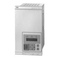
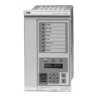
ABB REX 521 Technical Reference Manual, General (72 pages)
Protection Relay
Brand:
ABB
| Category:
Relays
| Size: 2.12 MB
ABB REX 521 Operating Manual (20 pages)
Relay Retrofit Program, Cutting Tool
Brand:
ABB
| Category:
Power Tool
| Size: 13.82 MB
Table of Contents
Document Revision History
3
Related Documentation
3
Panel Cut-Out Dimensions
4
Finishing the Work
17
Advertisement
Related Products
ABB REM 610
ABB RET615 D
ABB RET615 G
ABB REM615 B
ABB REF615 J
ABB REF615 L
ABB REU615 B
ABB REJ 527
ABB REA 10 Series
ABB REL-300
ABB Categories
Industrial Equipment
Controller
Measuring Instruments
Battery Charger
DC Drives
More ABB Manuals
Login
Sign In
OR
Sign in with Facebook
Sign in with Google
Upload manual
Upload from disk
Upload from URL