Sign In
Upload
Manuals
Brands
ABB Manuals
Control Unit
ACS880-304 +A003 Series
ABB ACS880-304 +A003 Series Manuals
Manuals and User Guides for ABB ACS880-304 +A003 Series. We have
1
ABB ACS880-304 +A003 Series manual available for free PDF download: Hardware Manual
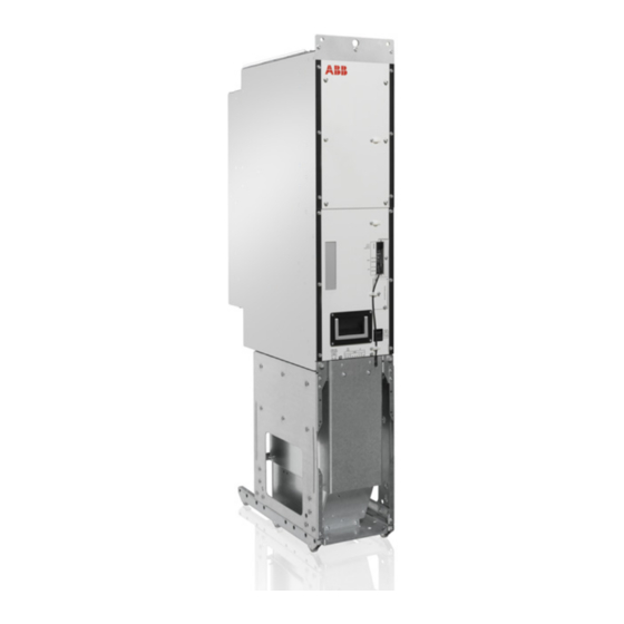
ABB ACS880-304 +A003 Series Hardware Manual (198 pages)
Diode supply modules
Brand:
ABB
| Category:
Control Unit
| Size: 51.06 MB
Table of Contents
Table of Contents
5
1 Introduction to the Manual
13
Contents of this Chapter
13
Applicability
13
Safety Instructions
13
Target Audience
13
Categorization by Frame Size and Option Code
14
Use of Component Designations
14
Terms and Abbreviations
14
Related Documents
14
2 Operation Principle and Hardware Description
17
Contents of this Chapter
17
Operation Principle
17
Simplified Main Circuit Diagram
18
Overcurrent and Short-Circuit Protection
18
Temperature Supervision
18
Overview Diagrams
19
Overview Diagram of the Drive System
19
Overview Diagram of the Supply Unit
20
Diode Supply Unit with Frame D6D or D7D Module
20
Diode Supply Unit with Frame D8D Module
21
Hardware of the Supply Modules
21
Layout Drawings of the Supply Modules
22
D6D Supply Module
22
D7D Supply Module
23
D8D Supply Module
24
Overview of Control Connections of ZCU-14 Control Unit
25
Supply Unit Control Devices
26
Auxiliary Voltage Switch
26
Operating Switch
26
Emergency Stop and Emergency Stop Reset Buttons
27
ACX-AP-X Control Panel
27
PC Connection
27
Fieldbus Control
27
Type Designation Label
28
Type Designation Key
29
3 Moving and Unpacking the Module
31
Contents of this Chapter
31
Moving and Lifting the Transport Package
31
Unpacking
31
Lifting the Modules
32
Moving the Modules
32
4 Cabinet Construction
33
Contents of this Chapter
33
Limitation of Liability
33
Switching, Disconnecting and Protecting Solution
33
Frame Sizes D6D and D7D
33
Frame Sizes D8D
34
Cabinet Configuration Overview
34
Acs880-304
34
Example of the AC Fuse Cooling
35
Installation Examples
36
D6D Module in a 400 MM Wide Rittal VX25 Enclosure
37
Installation Stages
38
Kits for D6D Module in a 400 MM Wide Rittal VX25 Enclosure
39
Stage 1: Installation of Common Parts
40
Stage 2: Main Switch-Disconnector and Main Contactor Installation
41
Stage 3: D6D/D7D Module Installation Parts
42
Stage 4: AC Busbar Installation
43
Stage 5: Main Circuit Cabling
44
Stage 6: Control Unit Installation
45
Stage 7: Module Installation
46
Stage 8: D6D Shroud Installation
47
D7D Module in a 400 MM Wide Rittal VX25 Enclosure
48
Installation Stages
49
Kits for D7D Module in a 400 MM Wide Rittal VX25 Enclosure
50
Stage 1: Installation of Common Parts
51
Stage 2: Main Switch-Disconnector and Main Contactor Installation
52
Stage 3: D6D/D7D Module Installation Parts
53
Stage 4: AC Busbar Installation
54
Stage 5: Main Circuit Cabling
55
Stage 6: Control Unit Installation
56
Stage 7: Module Installation
57
Stage 8: Shroud Installation
58
D8D Module in a 400 MM Wide Rittal VX25 Enclosure
59
Installation Stages
60
Kits for D8D Module in a 400 MM Wide Rittal VX25 Enclosure
61
Stage 1: Installation of Common Parts
62
Stage 2: D8D/D8T Module Installation Parts
63
Stage 3: Quick Connector Installation
64
Stage 4: D8D DC Busbar Installation
65
Stage 5: D8D Busbars to Quick Connector
66
Stage 6: D8D AC Busbar Installation
67
Stage 7: D8D Module Installation
68
Stage 8: D8D Shroud Installation
69
5 Electrical Installation
71
Contents of this Chapter
71
Safety and Liability
71
Electrical Safety Precautions
72
General Notes
73
Static Electricity
73
Optical Components
73
Measuring the Insulation
73
Measuring the Insulation of the Drive
73
Measuring the Insulation of the Input Power Cable
73
Connecting the Input Power Cables
74
Connection Diagrams
74
D6D, D7D Diode Supply Module
74
D8D Diode Supply Module
74
Connection Procedure of the Input Power Cables (D6D/D7D Supply Modules)
75
Connection Procedure of the Input Power Cables (D8D Supply Modules)
78
Connecting Power Supply for the Control Unit
80
Connection Diagram
80
Connection Procedure
80
Connecting Power Supply for the Module Fan
81
Connection Diagram
81
Connecting the Control Cables
81
Control Cable Connection Procedure
81
Grounding the Outer Shields of the Control Cables at the Cabinet Entry
81
Routing the Control Cables Inside the Cabinet
83
Connecting Control Cabling
83
Connecting a PC
84
6 Installation Checklist of the Drive
87
Contents of this Chapter
87
Checklist
87
7 Start-Up
89
Contents of this Chapter
89
Start-Up Procedure
90
Switching the Supply Unit off
91
Disconnecting and Temporary Grounding the Drive
91
8 Maintenance
93
Contents of this Chapter
93
Maintenance Intervals
93
Cabinet
95
Cleaning the Interior of the Cabinet
95
Cleaning the Door Air Inlets (IP22 and IP42)
95
Power Connections
96
Retightening the Power Connections
96
Fuses
96
Checking and Replacing the Module DC Fuses
96
Checking and Replacing the AC Fuses
97
Checking and Replacing the CVAR Board Fuses
98
Fan
98
Replacing the Fan of the Supply Module
99
Replacing the Cabinet Cooling Fan
100
Supply Module
100
Replacing the D6D and D7D Supply Module
101
Lifting Device for the D6D and D7D Supply Modules
104
Replacing the D8D Supply Module
105
Module Handling
105
Replacing the D8D Supply Module in the Rittal VX25 Enclosure
105
Control Panel
108
Cleaning the Control Panel
108
Replacing the Control Panel Battery
108
Control Unit
108
Replacing the Memory Unit
108
Replacing the ZCU-14 Control Unit Battery
109
Leds and Other Status Indicators
110
9 Ordering Information
111
Contents of this Chapter
111
Kit Code Key
112
Frame D6D and D7D
113
Diode Supply Modules
113
Control Panel
115
Control Electronics
116
ZCU Kit
116
Mechanical Installation Accessories and Tools
116
Module Installation Parts
116
Main Switch-Disconnector and Contactor Mechanics Kit
117
Shrouds
117
X6X/X7X Lifting Device
118
AC-Side Components
119
Main Switch-Disconnector Kits
119
AC Fuses
119
Main Contactors
120
Varistor Kit ACS880 for UL/CSA Installations
121
AC Busbars
122
DC-Side Components
122
DC Bus Installation Parts (for Rittal VX25 Enclosures)
122
Ventilation Kits
123
Air Inlet Kits 400 MM Cabinet
123
Air Outlet Kits 400 MM Cabinet
124
Cooling Fans
125
Miscellaneous
125
Plug Connectors
125
Frame D8D
126
Diode Supply Modules
126
Control Panel
127
Control Electronics
128
ZCU Kit
128
Mechanical Installation Accessories and Tools
128
Module Installation Parts
128
Shrouds
129
Ramp
130
AC-Side Components
130
Bracket for Flat-PLS Busbar Holder (Common AC)
130
Main Switch-Disconnector Kits
130
AC Fuses
131
Main Contactors
131
Varistor Kit ACS880 for UL/CSA Installations
132
AC Busbars
132
D8D AC Busbars to Quick Connector
133
Quick Connector
133
DC-Side Components
134
DC Bus Installation Parts (for Rittal VX25 Enclosures)
134
DC Busbars
134
DC Connection Flanges
135
Ventilation Kits
135
Air Inlet Kits 400 MM Cabinet
135
Air Outlet Kits 400 MM Cabinet
136
Miscellaneous
137
Plug Connectors
137
10 Technical Data
139
Contents of this Chapter
139
Ratings
139
Derating
140
Surrounding Air Temperature Derating
140
Altitude Derating
140
Fuses
141
AC Fuses
141
Iec
141
Iec/Ul
142
Ul
142
Internal DC Fuses
143
Fuses on CVAR Board
143
Dimensions and Weights
143
Free Space Requirements
144
Allowable Mounting Orientations
144
Losses, Cooling Data and Noise
145
Auxiliary Current Consumption
146
Tightening Torques
146
Electrical Connections
146
Mechanical Connections
146
Insulation Supports
146
Cable Lugs
147
Typical Power Cable Sizes
148
Electrical Power Network Specification
150
DC Connection Data
150
Efficiency
150
Control Unit Connection Data
150
Protection Classes
150
Ambient Conditions
151
Materials
152
Standards
152
Markings
152
Disclaimers
152
Generic Disclaimer
152
Cybersecurity Disclaimer
152
11 Control Units of the Drive
153
Contents of this Chapter
153
General
153
ZCU-14 Layout
154
ZCU-14 Default I/O Connection Diagram
155
External Power Supply for the Control Unit (XPOW)
157
Safe Torque off (XSTO)
157
FSO-XX Safety Functions Module Connection (X12)
157
Connector Data
158
ZCU-1X Ground Isolation Diagram
160
12 Dimension Drawings
161
Contents of this Chapter
161
Diode Supply Module (Frame D6D)
162
Diode Supply Module (Frame D7D)
163
Diode Supply Module (Frame D8D)
164
Quick Connector
166
Main Switch-Disconnectors
167
Os250D03
167
Os400J03
168
OS630D12 and OS600J12
169
OT1000E03, OT1250E03 and OT1200U03
170
Main Switch-Disconnector Handles
171
Ohb65J6, Ohb145J12
171
Ohb274J12
171
Auxiliary Contact OA1G10
172
Main Contactors
172
Af146-30-22B-13
172
Af460-30-22-70
173
Af750-30-22-70
174
Af1250-30-22-70
175
AC Fuses
176
170M3814D, 170M3817D, 170M6809D, 170M6812D
176
170M6415 and 170M6419
177
URD 33 TT F 1100 and 6,9 URD 73 TT F 1600
180
ZCU-14 Control Unit
181
Support Plate for ZCU-14
182
ACS-AP-X Control Panel with Door Mounting Kit
183
Ramp
184
D6D/D7D Cabinet Cooling Fan
186
CVAR Board
187
13 Example Circuit Diagrams
188
Contents of this Chapter
188
Component Designations Used in the Diagrams
188
D8D Circuit Diagrams
188
Differences of the DSU DXD Circuit Diagrams
188
Frames D6D and D7D - Main Supply, Auxiliary Voltage Transformer, DSU Module (Sheet 001)
188
Frame D6D - Auxiliary Voltage Distribution (Sheet 020)
189
Advertisement
Advertisement
Related Products
ABB ACS880-204LC
ABB ACS880-04F
ABB ACS801
ABB ACS811
ABB ACS831
ABB ACS802
ABB ACS804
ABB ACS810-04
ABB ACS104
ABB ACSM1-204
ABB Categories
Industrial Equipment
Controller
Measuring Instruments
Battery Charger
DC Drives
More ABB Manuals
Login
Sign In
OR
Sign in with Facebook
Sign in with Google
Upload manual
Upload from disk
Upload from URL