Sign In
Upload
Manuals
Brands
3M Manuals
Measuring Instruments
EVM-7
3M EVM-7 Manuals
Manuals and User Guides for 3M EVM-7. We have
1
3M EVM-7 manual available for free PDF download: User Manual
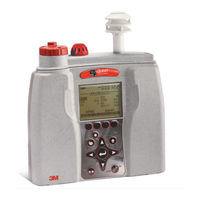
3M EVM-7 User Manual (179 pages)
Environmental Monitor
Brand:
3M
| Category:
Measuring Instruments
| Size: 4.08 MB
Table of Contents
Dangers, Warnings, & Cautions
2
Table of Contents
4
Chapter 1: Introduction
11
Particulate Sampling (Aerosols/Dust Vapors)
12
Particulate Path
12
Figure 1-1: Particulate Path Diagram
12
Particulate Sizes
13
Figure 1-2: Particulates and Diameter Size
13
Particulates and Cut-Point
14
Collecting/Sensing the Particulates
14
Gravimetric Sampling
14
Pump
14
Gas Sensors Sampling
15
Gas Sensors and Path
15
Volatile Organic Compounds (Voc's) Sampling
16
Temperature, Relative Humidity, Dew Point
16
What the Standards Say
16
Resources
17
EVM Series
17
Applications
17
Models Explained
19
Chapter 2: Getting Started
21
Checking the Equipment
21
Figure 2-1: Identifying Your Equipment
21
Display and Keypad
22
Diagram
22
Figure 2-2: EVM Keypad and Display Explained
22
Keypad Description
23
Table 2-1: Keypad/User Interface Explained
23
Turning on
24
Start Screen Explanation
24
Figure 2-3: Start Screen Defined
24
Navigating
25
Indicators/Icons on the Display
25
Table 2-2: Indicators (I.e., Run, Stop, Battery, Altf )
25
Turning off
26
Instrument Information
26
Unit Information Screen
26
Figure 2-4: Unit Information Screen
26
Figure 2-5: Selecting Unit Info. Sensors
27
Figure 2-6: Viewing Installed Sensors
27
TM Detection Management Software DMS
28
Communicating
28
Figure 2-7: Communicating with QSP-II Via USB Cable
28
Powering and Outputs on the EVM
29
Battery
29
Charging
29
Outputs
29
Figure 2-8: USB, Power Jack and Digital Output Port
29
Chapter 3:Setting Up the EVM
31
Setting up Parameters Via the Keypad
31
Time and Date Setting
31
Checking Battery Power
32
Figure 3-1: Time-Date Screen Parameters
32
Figure 3-2: Start Screen
33
Figure 3-3: Battery Screen
33
Display: Language, Contrast, & Key Click
34
Table 3-1: Display Settings Explained
34
Setting Logging and Viewing Run Time
35
Figure 3-4: Screen Display Settings
35
Table 3-2: Logged Intervals and Selecting Logged Measurements
36
PID Correction - Adding/Editing
37
Figure 3-5: Logging Screen
37
Figure 3-6: Estimated Run Time for Logging Screen
37
Figure 3-7: PID Correction Factor
38
Figure 3-8: PID Correction Factor Displayed on Measurement Screens
38
Changing Units (Temperature, Particulates, PID, and Air Velocity)
39
Figure 3-9: Units Screen
39
Setting up Particulate Settings
40
Setting Profiles (Particulate Correction Factors)
40
How Particulate Factors Are Adjusted and Calculated
40
Dust Correction Factors (Profiles)
41
Figure 3-10: Edit Profiles for Dust Calibration
41
Figure 3-11: Entering a Profile for Particulate Calibration
42
Particulate Pump: Enable or Disable
43
Resetting the Gravimetric Filter
43
Auxiliary Input/Output
44
Digital Output
44
Figure 3-12: Particulate Setup Screen
44
Figure 3-13: Configuring Digital Output
45
Table 3-3: Digital Out/Logic Settings
45
Air Velocity
46
Figure 3-14: Air Velocity Setting
46
Analog-Out
47
Figure 3-15: Analog out Results with Temperature as Output
47
Figure 3-16: Analog-Out Screen
47
Restoring Default Factory Settings
48
Figure 3-17: Defaults Screen (Restoring Factory Settings)
48
Figure 3-18: Restoring Default Calibrations
48
Backlight Setting
49
Resetting the EVM
49
Figure 3-19: Backlight Key
49
Lock/Secure Run And/Or Setup
50
Figure 3-20: Lock Softkey
50
Unlock Run And/Or Setup
51
Figure 3-21: Setting Lock/Secure
51
Auto-Run
52
Auto-Run and Timed-Run Mode
52
Figure 3-22: Selecting Auto-Run with Timed-Run Mode
52
Auto-Run with Date Mode
53
Figure 3-23: Setting Timed-Run and Duration
53
Figure 3-24: Selecting Auto-Run with Date Mode
54
Figure 3-25: Setting Auto-Run Date Mode
54
Auto-Run with Day of Week (DOW) Mode
55
Figure 3-26: Setting Auto-Run DOW Mode
55
Chapter 4: Calibrate Sensors
57
Placement and Calibration of Sensors
57
Inserting and Removing Sensors
57
Figure 4-1: Sensor Housing and Manifold
58
Figure 4-2: Sensors' Locations
58
Calibrating Particulates
59
Impactor and Use
59
Figure 4-3: How the Impactor Functions
59
Adjusting the Impactor/Turret Setting
60
Figure 4-4: PM2.5 Impactor Setting Example
60
Figure 4-5: Adjusting Impactor/Turret Setting
61
Particulates Calibration (Zero Cal)
62
Figure 4-6: Particulate Zero Cal with HEPA Filter
62
Figure 4-7: Selecting Calibration Screen
63
Figure 4-8: Particulate Cal Screen
63
Figure 4-9: Particulate Calibration and Ready Screen
64
Figure 4-10: Particulate Calibration and Waiting Screen
64
Figure 4-11: Particulate Calibration Pause Screen
65
Figure 4-12: Zero Cal Set for Particulates
65
Particulate Advanced Calibration (Gravimetric)
66
Gravimetric Calibration Overview
66
Performing a Gravimetric Calibration
67
Figure 4-13: Reset Gravimetric Setting
67
Pump Flow Rate Calibration
68
Figure 4-14: Pump Flow Rate Calibration
68
Toxic Gas Sensors
69
Figure 4-15: Flow Rate Calibration
69
Cross Sensitivity
70
How Sensors Operate
70
Quality Calibrations
70
Table 4-1: Cross-Sensitivity Table of Interfering Gas
70
About Sensors and Cal Storage
71
Calibration History and Sensor Serial Numbers
71
Figure 4-16: Calibration History for EVM
71
Applying a Gas Sensor
72
Figure 4-17: Applying a Gas Sensor
72
Calibrating Toxic Gas Sensors
73
Toxic Gas Zero Calibration
73
Ozone Calibration for Zero and Span
73
Figure 4-18: Selecting Sensor for Calibration Process
74
Figure 4-19: Calibration Zero Screen
74
Toxic Gas Span Calibration
75
Figure 4-20: Calibration Zero Pause Screen
75
Table 4-2: Gas Calibration Softkeys Explained
75
Figure 4-21: Span Calibration
76
Figure 4-22: Saved Calibration Screen
76
Calibrating CO
77
And O
77
CO 2 Accuracy
77
O 2 Accuracy
77
Figure 4-23: Selecting a Calibration Sensor
78
Figure 4-24: Calibration CO2 Ready Screen
79
Figure 4-25: Setting CO Span Cal Screen
80
Figure 4-26: Saved Calibration
80
Calibrating Photo-Ionization Detector (PID) Sensor
81
PID Parts Per Million (Ppm) Zero Calibration
81
PID Parts Per Billion (Ppb) Zero Calibration
81
PID Span Calibration
82
Figure 4-27: Selecting PID Sensor for Calibration Process
82
Figure 4-28: Calibration Mode Screen
82
Figure 4-29: PID Calibration Span Softkey
83
Calibrating Relative Humidity and Temperature
84
Figure 4-30: Saved Calibration Screen
84
Figure 4-31: Temperature Calibration
85
Calibration History
86
Figure 4-32: Calibration History Screen
86
Verify Calibration and Drifting Analysis
87
Figure 4-33: Calibrate Offset Verify Screen for PID Sensor
87
Figure 4-34: Calibrating PID
88
Chapter 5: Measuring and Viewing
90
Overview of Running a Session
90
Figure 5-1: Quick Help List for Running a Study
90
Measuring
91
Understanding What Data Is Stored
91
Summary Data
91
Logged Data/ Time History
91
Figure 5-2: Sample Summary Data from QSP-II Reporting
91
Running and Stopping
92
Figure 5-3: Sample Time History Data (or Logged Data) Chart
92
Measurement Screens and Navigation
93
Figure 5-4: Composite Measurement Screen in Run Mode
93
Unit Defined
94
Table 5-1: Unit Abbreviations
94
About the Measurement Softkeys
95
Figure 5-5: Example of Measurement Softkey Menus
95
Table 5-2: Measurement Softkeys Explained
95
Particulate Measurement Screen
96
Figure 5-6: Particulate Measurement Screen
96
Table 5-2: Measurement Softkeys Explained (Continued)
96
Extending Run-Time for PM Measurements
97
Impactors and Particulate Measuring
97
Changing Particulate Measurements
98
Figure 5-7: Selecting a Measurement Calculation
98
Relative Humidity & Temperature Measurements
99
Relative Humidity and Temperature Screen
99
Figure 5-8: RH and Temperature Measurement Screen
99
Table 5-3: Measurement Values Explained
99
Gas Measurements
100
Gas Screen
100
Composite Measurement
100
Figure 5-9: Gas Measurement Screen
100
Composite Screens
101
Figure 5-10: Composite Measurement Screen
101
Air Velocity Meaursurement Screen
102
Figure 5-11: Attaching Airprobe and Measuring Air Velocity
102
Summary Data
103
Viewing Details in the Measurement Screen
103
Trend Data
103
Figure 5-12: Details of the Composite Measurement Screen
103
Viewing Trend Data in the Measurement Screen
104
Figure 5-13: Selecting Trend Softkey
104
Figure 5-14: Trend Screen for PM (Dust)
104
Past Session
105
Summary Data Screen
105
Figure 5-15: Past Session Screen
105
Figure 5-16: Past Session with Files Selected
106
Table 5-4: Past Session Files Softkeys Explained
106
File System Menu
107
Deleting Sessions Individually
107
Figure 5-17: Summary Screen of a Past Session
107
Delete All Sessions
108
Figure 5-18: Delete Session Message
108
Figure 5-19: Delete All Sessions Message
108
Memory Remaining and File Properties
109
Figure 5-20: File Systems Properties Screen
109
Estimated Run Time
110
Figure 5-21: Viewing Estimated Run Time
110
Chapter 6: DMS (Software)
111
EVM Communication
111
Figure 6: Communicating with the EVM and DMS
111
Figure 6-1: DMS Start Page and Setup/Download Options
111
Downloading Data with the EVM
112
EVM: Viewing Data
112
Selecting a Session/Study
112
Figure 6-2: EVM and Downloading
112
Figure 6-3: Data Finder Page
112
EVM Panel Layout View (PLV) Page
113
Figure 6-4: Charts and Graphs (Panels)
113
EVM Reports and Printing
114
Figure 6-5: EVM Data in a Report Format
114
Customizing Reports
115
Figure 6-6: Customizing DMS Reports
115
EVM Setup
116
Saving and Sending Configurations
116
General EVM Setup
116
Figure 6-7: Saving and Sending EVM Setups
116
EVM General Parameters Table
117
EVM and Logging Settings
117
Figure 6-8: General EVM Setups
117
EVM Logging Parameters Table
118
Figure 6-9: Logging EVM Setups
118
EVM and Auto-Run Setting
119
Timed-Run and Auto-Run Setting
119
Date and Auto-Run Setting
119
Figure 6-10: EVM Timed-Run Auto-Run Setting
119
Day of Week and Auto-Run Setting
120
Figure 6-11: EVM Auto-Run with Date Setting
120
Figure 6-12: EVM Auto-Run with Day of Week Setting
120
EVM and Security Settings
121
EVM and Triggering Settings
121
Figure 6-13: EVM Auto-Run with Day of Week Setting
121
Figure 6-14: EVM Triggering Setup
122
EVM and Particulate Settings
123
EVM and Particulates Setup
123
Figure 6-15: EVM Auto-Run with Day of Week
123
Chapter 7: Maintenance & Cleaning
125
Overview
125
PID Sensor
125
Removing and Installing PID Sensor
126
Figure 7-1: Removing and Inserting PID Sensor
126
Maintenance and Cleaning Overview of PID
127
Cleaning PID Sensor
127
Figure 7-2: Removing Intelligent-Sensor Casing with PID
128
Figure 7-3: Removing the Lamp with Removal Tool
128
Optical Engine: Maintenance and Cleaning
130
Impactor Care
133
Impactors and When to Clean
134
Gravimetric Cassette and Filter Paper
135
Appendix A: Specifications
136
Replacement and Optional Parts
146
Appendix B: Customer Service
148
Contacting 3M Quest Tecnologies Instrumentation
148
International Customers
148
Calibration
148
Warranty
149
Appendix B: Glossary of Terms
150
Appendix C: PID Sensor and Correction Factors Tables
156
Appendix D: Faq's; Particulate Measurements
168
Appendix E: System Errors Displayed on the EVM Series
173
Advertisement
Advertisement
Related Products
3M Edge eg5
3M EVM Series
3M EVM-4
3M EVM-3
3M ESD Pro
3M eg4
3M eg3
3M Touch Screen Controller EX122
3M ECAM-20 MM-D
3M Scott Safety ELSA 2000
3M Categories
Projector
Respiratory Product
Safety Equipment
Water Filtration Systems
Headsets
More 3M Manuals
Login
Sign In
OR
Sign in with Facebook
Sign in with Google
Upload manual
Upload from disk
Upload from URL