Bosch B5512 Reference Manual
Hide thumbs
Also See for B5512:
- Owner's manual (188 pages) ,
- Quick start manual (2 pages) ,
- Operation manual (224 pages)

Related Manuals for Bosch B5512


Summary of Contents for Bosch B5512
- Page 1 Control Panel B5512/B4512/B3512 (B5512E/B4512E/B3512E) Installation and System Reference Guide...
-
Page 3: Table Of Contents
Lightning 1.2.1 Effects of lighting 1.2.2 Installation precautions 1.2.3 Warranty Introduction About documentation 2.1.1 Related documentation Bosch Security Systems, Inc. product manufacturing dates System overview Configuration and parts 3.1.1 Control panel capacities 3.1.2 Parts list 3.1.3 Order separately Accessories Features 3.3.1... - Page 4 B921C Two-line Capacitive Keypad with Inputs 9.1.4 B930 ATM Style Alphanumeric Keypad 9.1.5 B942 Touch Screen Keypad 9.1.6 Shortcuts and custom functions 9.1.7 Address settings 9.1.8 Supervision 2015.07 | 12 | F.01U.287.180 Installation and System Reference Guide Bosch Security Systems, Inc.
- Page 5 Fire walk test 15.2.2 Intrusion walk test 15.2.3 Service walk test 15.2.4 Invisible walk test Control panel board overview System wiring diagrams 17.1 System wiring overview Bosch Security Systems, Inc. Installation and System Reference Guide 2015.07 | 12 | F.01U.287.180...
- Page 6 [2] RF Repeater Menu > [1] Add Repeater 19.2.5 [2] RF Repeater Menu > [2] Replace Repeater 19.2.6 [2] RF Repeater Menu > [3] Remove Repeater 2015.07 | 12 | F.01U.287.180 Installation and System Reference Guide Bosch Security Systems, Inc.
- Page 7 SDI2 address information 21.3 Device numbers (zzz, dddd) 21.4 Communication Trouble device numbers (zzzz) 21.5 Special User IDs (uuuu, iiii) 21.6 Keypad alarm virtual point numbers (ppp, pppp) Bosch Security Systems, Inc. Installation and System Reference Guide 2015.07 | 12 | F.01U.287.180...
-
Page 8: Certifications, Approvals, Listings, And Safety
Listed for Control Panel Standard - Features for False Alarm Reduction ANSI/SIA CP-01-2010. 1.1.4 Department of Defense (DoD) The B5512/B4512/B3512 control panels were granted approval for Department of Defense (DoD) installations in Sensitive Compartmented Information Facilities (SCIF). 1.1.5 California State Fire Marshal (CSFM) Listed for Household Fire Alarm. -
Page 9: Industry Canada (Ic)
Part 68 The B430 module by Bosch Security Systems, Inc. is registered with the Federal Communication Commission (FCC) under Part 68, for connection to the public telephone system using an RJ31X or RJ38X phone line connection jack installed by the local telephone company. -
Page 10: Warranty
When your data lines must cross the path of AC or other wiring, cross perpendicular to the lines. 1.2.3 Warranty The warranty does not cover physical damage due to lightning. 2015.07 | 12 | F.01U.287.180 Installation and System Reference Guide Bosch Security Systems, Inc. -
Page 11: Introduction
These indicate a hazardous situation which, if not avoided, could result in death or serious injury. Copyright This document is the intellectual property of Bosch Security Systems, Inc. and is protected by copyright. All rights reserved. Trademarks All hardware and software product names used in this document are likely to be registered trademarks and must be treated accordingly. - Page 12 Details tab selected. Click on the Documents tab, and then click the desired language listed to the right of the desired document. Call Bosch Security Systems, Inc., Technical Support (1-800-289-0096) if you need additional assistance. Control panel documents...
-
Page 13: Bosch Security Systems, Inc. Product Manufacturing Dates
Located on the documentation CD shipped with the module. Bosch Security Systems, Inc. product manufacturing dates Use the serial number located on the product label and refer to the Bosch Security Systems, Inc. website at http://www.boschsecurity.com/datecodes/. The following image shows an example of a product label and highlights where to find the manufacturing date within the serial number. -
Page 14: System Overview
Control Panel System overview B91x/B92x/B93x/B94x Use keypads to operate the control panel by area. B5512 control panels support up to 4 areas. B810 B4512 control panels support up to 2 areas. RADION receiver SDs B3512 control panels support 1 area. -
Page 15: Configuration And Parts
Control panels ship assembled from the factory with the following parts: Literature – Control Panels (B5512/B4512/B3512) UL Installation Guide – Control Panels (B5512/B4512/B3512) Owner’s Manual – Control Panels (B5512/B4512/B3512) SIA Quick Reference Guide – Control Panels (B5512/B4512/B3512) Documentation CD – Enclosure Wiring Label (B5512/B4512/B3512) HW pack –... -
Page 16: Order Separately
ATM Style Alphanumeric Keypad (SDI2) B942 Touch Screen Keypad (B942W white) CX4010 UL Listed Class 2 Transformer 18 VAC 22 VA 60 Hz D125B Dual Class B Initiating Module 2015.07 | 12 | F.01U.287.180 Installation and System Reference Guide Bosch Security Systems, Inc. - Page 17 Refer to the Dual Class B Inititating Module (D125B) Installation Instructions (P/N: F01U036340) for compatible D125B devices. Compatible detectors The following is a sampling of wired detectors suitable for use on approved applications. Other UL listed devices are available. Bosch Security Systems, Inc. Installation and System Reference Guide 2015.07 | 12 | F.01U.287.180...
- Page 18 Repeater RFSM-A RADION smoke Smoke detector RFPR-12-A RADION PIR PIR detector RFPR-C12-A RADION PIR C PIR curtain detector RFUN-A RADION universal Universal transmitter UL 985 only. 2015.07 | 12 | F.01U.287.180 Installation and System Reference Guide Bosch Security Systems, Inc.
- Page 19 For specific installation and operation instructions, please refer to manufacturers' manuals. D125B 2-wire smoke compatibility table Refer to the Dual Class B Initiating Module (D125B) Installation Instructions. Bosch Security Systems, Inc. Installation and System Reference Guide 2015.07 | 12 | F.01U.287.180...
-
Page 20: Features
3.3.3 Areas and accounts B5512 control panels support up to 4 areas. B4512 control panels support up to 2 areas. B3512 control panels support 1 area. You can assign all points to a single area or distribute them over multiple areas. -
Page 21: Digital Communication
When the event log reaches a programmed threshold of stored events, it can send an optional report to a receiver. B5512 control panels store up to 255 events. B4512 and B3512 control panels store up to 127. -
Page 22: Installation Checklist
Before installing and operating the control panel, read these instructions. Failure to follow these procedures may cause the device not to function properly. Bosch Security Systems Inc. is not responsible for any devices that are improperly installed, tested, or maintained. -
Page 23: Control Panel Installation
Mount the enclosure in the desired location. Use all enclosure mounting holes. Refer to the mounting instructions supplied with the selected enclosure. Pull the wires into the enclosure. Install the supplied Enclosure Wiring Label (B5512/B4512/B3512) on the inside of the enclosure door. Notice! Electromagnetic interference (EMI) can cause problems on long wire runs. - Page 24 1 ᅳ B10 Medium Control Panel Enclosure 2 ᅳ B11 Small Control Panel Enclosure 3 ᅳ Mounting clip locations for the B5512/B4512/B3512 Snap the four supplied plastic standoffs onto four enclosure support posts. If using the B12 Mounting Plate for D8103 Enclosure, attach the standoffs to the plate support posts.
-
Page 25: Connect Earth Ground
COM terminals), remove the door covering the jumper pins, and move the jumper to the left two pins. The OUTPUT A LED lights when OUTPUT A is active. Refer to the figure below or to the Enclosure Wiring Label (B5512/B4512/B3512) to set the OUTPUT A jumper. Bosch Security Systems, Inc. -
Page 26: Control Panel To Module Wiring Overview
OUTPUT A PWR A B COM Figure 5.6: SDI2 devices daisy chained with terminal wiring (B5512 shown) Using interconnect wiring Interconnect wiring connectors parallel the SDI2 terminals (PWR, A, B, and COM). In installations with multiple SDI2 modules, using interconnect wiring makes the installation quicker and easier than using terminal strip wiring. - Page 27 COM AUX 18VAC + BAT - OUTPUT A PWR A B COM B COM B COM Figure 5.7: SDI2 devices daisy chained with interconnect wiring (B5512 shown) Bosch Security Systems, Inc. Installation and System Reference Guide 2015.07 | 12 | F.01U.287.180...
-
Page 28: Power Supply
Plug the transformer into an unswitched, 120 VAC, 60 Hz power outlet only. Secure the transformer to the outlet with the screw provided (not applicable in Cananda). Secondary (DC) power 2015.07 | 12 | F.01U.287.180 Installation and System Reference Guide Bosch Security Systems, Inc. -
Page 29: Install The Battery
The battery terminals and wire are not power limited. Maintain a 0.250 in (6.4 mm) space between the battery terminals, battery wiring, and all other wiring. Battery wiring cannot share the same conduit, conduit fittings, or conduit knockouts with other wiring. Bosch Security Systems, Inc. Installation and System Reference Guide 2015.07 | 12 | F.01U.287.180... -
Page 30: Battery Maintenance
+ BAT - OUTPUT A PWR A B COM Figure 6.1: Non-power-limited wiring (B5512 shown) Callout ᅳ Description 1 ᅳ Conduit required for use with external batteries 2 ᅳ To CX4010 UL Listed Class 2 Transformer 18 VAC 22 VA 60 Hz 3 ᅳ... -
Page 31: Battery Supervision
Fire and Burglar applications. For Burglar applications, an additional 2 A of alarm power is available, allowing 2 A of standby current and up to 4 A of alarm current. The B5512 control panels support up to 4 B520 modules. The B4512/B3512 control panels support up to 2 B520 modules. -
Page 32: Supervision
Do not use telephone or electrical ground for the earth ground connection. Use 14 AWG (1.8 mm) to 16 AWG (1.5 mm) wire when making the connection. 2015.07 | 12 | F.01U.287.180 Installation and System Reference Guide Bosch Security Systems, Inc. -
Page 33: Powered Device And Battery Wiring
PWR A B COM PWR A B COM PWR A B COM Figure 6.3: B520 to the control panel wiring (B5512 shown) Callout ᅳ Description 1 ᅳ Control panel 2 ᅳ B520 Auxiliary Power Supply Module 3 ᅳ Terminal strip wiring 6.3.5... - Page 34 1 ᅳ B520 Auxiliary Power Supply Module 2 ᅳ Battery 2 (BATT 2) - (12 V nominal lead acid) 3 ᅳ Battery 1 (BATT 1) - (12 V nominal lead acid) 2015.07 | 12 | F.01U.287.180 Installation and System Reference Guide Bosch Security Systems, Inc.
-
Page 35: Telephone Communications
Plug-in Telephone Communicator (B430) Installation Guide. Notification The B430 module by Bosch Security Systems, Inc. is registered with the Federal Communication Commission (FCC) under Part 68, for connection to the public telephone system using an RJ31X or RJ38X phone line connection jack installed by the local telephone company. -
Page 36: Diagnostic Leds
| Telephone communications Control Panel Wire to the phone line Figure 7.1: PTSN module wiring (B5512 shown) Callout ᅳ Description 1 ᅳ Premises telephone 2 ᅳ Incoming Telco line 3 ᅳ Installer telephone test set 4 ᅳ RJ-45 phone connector 7.1.3... -
Page 37: Telephone Line Monitor
The telephone line monitor cannot recognize this trouble condition. Bosch Security Systems, Inc. Installation and System Reference Guide 2015.07 | 12 | F.01U.287.180... -
Page 38: Called Party Disconnect
If the queue reaches the capacity of panel event log, the oldest reports are cleared (overwritten). 2015.07 | 12 | F.01U.287.180 Installation and System Reference Guide Bosch Security Systems, Inc. -
Page 39: Ip Communications
3. If the control panel does use the Ethernet for IP communication, power down the control panel and remove the Ethernet cable that connects the control panel to the network. Bosch Security Systems, Inc. Installation and System Reference Guide 2015.07 | 12 | F.01U.287.180... -
Page 40: On-Board Ethernet Diagnostic Leds
MODULE RELEASE ETHERNET 100BASE-T LINK Figure 8.1: On-board Ethernet and LEDs (B5512 shown) Callout ᅳ Description 1 ᅳ 100BASE-T LED (green) 2 ᅳ LINK LED (yellow) Refer to the following tables for information on the 100BASE-T and LINK LEDs. Flash pattern... -
Page 41: Conettix Plug-In Cellular Communicators
The module plugs into a connector and is held in place with a plug-in module retention clip. The module handle and support on top of the module hold the unit during installation. Bosch Security Systems, Inc. Installation and System Reference Guide... -
Page 42: Signal Strength And Diagnostic Leds
Connect the antenna cable to the module. Secure the antenna cable to the outside of the enclosure. Figure 8.2: Plug-in celluar module wiring (B440 and B5512 shown) 8.2.3 Signal strength and diagnostic LEDs Five LED patterns indicate that you correctly secured the module in the control panel, and indicate the signal strength obtained by the module. -
Page 43: B426 Ethernet Communication Module
Module supervision. The control panel supervises the module through polling. If the module does not respond to the control panel polling, the control panel declares the device missing. Bosch Security Systems, Inc. Installation and System Reference Guide 2015.07 | 12 | F.01U.287.180... -
Page 44: B426 Module Faults
1000 ft (305 m) using 18 AWG to 22 AWG (1.02 mm to 0.65 mm) wire from the control panel. Use the screws provided with the module to secure the module in the enclosure. 2015.07 | 12 | F.01U.287.180 Installation and System Reference Guide Bosch Security Systems, Inc. - Page 45 COM AUX PWR A B COM PWR A B COM Figure 8.3: B426 to control panel wiring - terminal strip or interconnect wiring connector (B5512 shown) Callout ᅳ Description 1 ᅳ Control panel 2 ᅳ Module 3 ᅳ Terminal strip wiring 4 ᅳ...
-
Page 46: Diagnostic Leds
On Steady LED trouble state. Module is not powered, or some other trouble condition prohibits the module from controlling the heartbeat LED. Table 8.5: Heartbeat LED descriptions 2015.07 | 12 | F.01U.287.180 Installation and System Reference Guide Bosch Security Systems, Inc. -
Page 47: B450 Conettix Plug-In Communicator Interface
PWR, A, B, and COM, or using the SDI2 interconnect wiring connector. This section includes basic installation instructions. For detailed installation instructions, refer to the Conettix Plug-in Communicator Interface (B450) Installation and Operation Guide. Bosch Security Systems, Inc. Installation and System Reference Guide 2015.07 | 12 | F.01U.287.180... -
Page 48: Sdi2 Address Settings
COM on the control panel, or you can use the interconnect wiring connector and the included interconnect cable. For terminal wiring, use 18 AWG to 22 AWG (1.02 mm to 0.65 mm) wire. 2015.07 | 12 | F.01U.287.180 Installation and System Reference Guide Bosch Security Systems, Inc. -
Page 49: Diagnostic Leds
COM AUX PWR A B COM PWR A B COM Figure 8.5: B450 to control panel wiring - terminal strip or interconnect wiring connector (B5512 shown) Callout ᅳ Description 1 ᅳ Control panel 2 ᅳ Module 3 ᅳTerminal strip wiring 4 ᅳ... -
Page 50: Compatible Receivers For Ip Communication
D6200 version Conettix D6600 Communications Receiver/Gateway 01.03.02 1.35 (with D6641 line cards installed only) Conettix D6100IPv6 Communications Receiver/Gateway 61.10.00 2.10 Conettix D6100i Communications Receiver/Gateway 61.04.00 1.35 2015.07 | 12 | F.01U.287.180 Installation and System Reference Guide Bosch Security Systems, Inc. - Page 51 D6200 version Conettix D6600 Communications Receiver/Gateway 01.11.00 2.20 (with D6641 line cards installed only) Conettix D6100IPv6 Communications Receiver/Gateway 61.11.00 2.20 Conettix D6100i Communications Receiver/Gateway 61.11.00 2.20 Bosch Security Systems, Inc. Installation and System Reference Guide 2015.07 | 12 | F.01U.287.180...
-
Page 52: Keypads, Keyswitches, Keyfobs And Transmitters
The system can use keypads, maintained or momentary contact keyswitches, wireless RADION keyfobs or Inovonics transmitters, or a combination of these options to turn areas on and off. B5512 control panels support up to 4 areas. B4512 control panels support up to 2 areas. B3512 control panels support 1 area. -
Page 53: B942 Touch Screen Keypad
Installing a keypad: Open the keypad. Set the keypad address using the address switches Use the provided anchors and screws to mount the keypad base on the wall. Bosch Security Systems, Inc. Installation and System Reference Guide 2015.07 | 12 | F.01U.287.180... -
Page 54: Sensor Loops Overview And Wiring (B921C/B942/B942W Only)
3 COM 4 5 COM 6 7 COM 8 - 12 V + COM AUX PWR A B COM Figure 9.1: Keypad to control panel wiring (B5512 shown) 1 Control panel 2 Keypad 3 Terminal strip wiring 9.1.10 Sensor loops overview and wiring (B921C/B942/B942W only) The keypad detects three states (Open, Supervised, Short) on its sensor loops and sends the conditions to the control panel. -
Page 55: Output Wiring (B942/B942W Only)
Off (disarmed). Connect the keyswitch to an on-board or off-board point’s sensor loop. You can program outputs to activate arming status LEDs. Refer to Outputs in RPS Help and Point Assignments in the control panel Program Entry Guide. Bosch Security Systems, Inc. Installation and System Reference Guide 2015.07 | 12 | F.01U.287.180... -
Page 56: Operation
3 ᅳ Common 7 ᅳ Momentary short on the circuit toggles the arming state 4 ᅳ Point input Keyswitches are not intended for use in UL listed systems. 2015.07 | 12 | F.01U.287.180 Installation and System Reference Guide Bosch Security Systems, Inc. -
Page 57: Radion Keyfobs And Inovonics Pendant Transmitters
Keypads, keyswitches, keyfobs and transmitters | en RADION keyfobs and Inovonics pendant transmitters B5512 control panels support up to 50 wireless RADION keyfobs or 50 Inovonics pendant transmitters, one for each of the 50 users the control panel supports. B4512 control panels support up to 32 wireless RADION keyfobs or 32 Inovonics pendant transmitters, one for each of the 32 users the control panel supports. -
Page 58: On-Board Outputs
As a powered output, it can provide alarm power or switched auxiliary power. The default configuration for Output A makes it a powered output providing alarm power. Use OUTPUT PARAMETERS in RPS to configure programmable outputs. 2015.07 | 12 | F.01U.287.180 Installation and System Reference Guide Bosch Security Systems, Inc. -
Page 59: Open Collector Outputs
X2 - OUTPUT A PWR A B COM X2 + Figure 10.1: OUTPUT B and C wiring (B5512 shown) Callout ᅳ Description 1 ᅳ Control panel 2 ᅳ D134 Dual Relay Module Use OUTPUT PARAMETERS in RPS to configure programmable outputs. -
Page 60: Off-Board Outputs
You can configure the function for each output on the module individually. Refer to Output Parameters in RPS Help or the control panel Program Entry Guide. B5512 control panels support up to 5 modules to provide 40 outputs. B4512 control panels support up to 3 modules to provide 24 outputs. -
Page 61: Supervision
Off-board outputs | en Octo-output module number Supported outputs 51 – 58* * Valid for the B5512 only. Table 11.1: Octo-output module valid relay numbers 11.1.2 Supervision The control panel enables supervision of B308 Octo-output Modules on the SDI2 bus when the Output Source of an off-board output is set to Octo-output. - Page 62 Figure 11.1: B308 to control panel wiring - terminal strip or interconnect wiring connector Callout ᅳ Description 1 ᅳ Control panel 2 ᅳ Module 3 ᅳ Terminal strip wiring 4 ᅳ Interconnect cable (P/N: F01U079745) (included) 2015.07 | 12 | F.01U.287.180 Installation and System Reference Guide Bosch Security Systems, Inc.
-
Page 63: On-Board Points
The total resistance for the wire length and contacts, excluding the end-of-line (EOL) resistor, must not exceed 100 Ω. Bosch Security Systems, Inc. Installation and System Reference Guide 2015.07 | 12 | F.01U.287.180... - Page 64 Greater than 3.7 VDC, but less than 5.0 VDC. Normal Greater than 2.0 VDC, but less than 3.0 VDC. Shorted Greater than 0.0 VDC, but less than 1.3 VDC. Table 12.1: Point voltage parameters 2015.07 | 12 | F.01U.287.180 Installation and System Reference Guide Bosch Security Systems, Inc.
-
Page 65: Dual Eol Resistor Circuit Style
Debounce does not apply to points with Point Source configured as Wireless, Output, or IP Camera. Bosch Security Systems, Inc. Installation and System Reference Guide 2015.07 | 12 | F.01U.287.180... -
Page 66: Off-Board Points
The module points work in the same way as the points on the control panel. B5512 control panels support up to 4 modules. B4512 control panels support up to 2 modules. The B3512 does not support the B208. -
Page 67: Installation And Control Panel Wiring (B208)
PWR A B COM Figure 13.1: B208 to control panel wiring - terminal strip or interconnect wiring connector Callout ᅳ Description 1 ᅳ Control panel 2 ᅳ Module Bosch Security Systems, Inc. Installation and System Reference Guide 2015.07 | 12 | F.01U.287.180... -
Page 68: Sensor Loops Overview And Wiring
UL does not permit normally closed loops for commercial fire applications. Notice! Optionally use these points for household fire applications. You can connect four-wire detectors to these points, for example. 2015.07 | 12 | F.01U.287.180 Installation and System Reference Guide Bosch Security Systems, Inc. - Page 69 Figure 13.2: B208 sensor loop wiring Callout ᅳ Description 1 ᅳ Module 2 ᅳ Sensor loop 3 ᅳ 1 kΩ EOL resistor (P/N: F01U026703) 4 ᅳ Wiring to additional sensor loops Bosch Security Systems, Inc. Installation and System Reference Guide 2015.07 | 12 | F.01U.287.180...
-
Page 70: Test Off-Board Points
An SDI2 Wireless point is considered assigned when its Point Source is Wireless and it has an RFID assigned. On-board points cannot produce Extra Point events. Points that are Service Bypassed cannot produce Extra Point events. 2015.07 | 12 | F.01U.287.180 Installation and System Reference Guide Bosch Security Systems, Inc. -
Page 71: Wireless Modules
Install the module on the base. Notice! Mount the receiver in a location removed from metal. Metal objects (duct work, wire mesh screens, boxes) reduce RF range. Bosch Security Systems, Inc. Installation and System Reference Guide 2015.07 | 12 | F.01U.287.180... -
Page 72: B820 Sdi2 Inovonics Interface Module
Installation and control panel wiring (B820) Ensure that there is enough power for the module and other powered devices you want connected to the system. Refer to On-board outputs, page 58. 2015.07 | 12 | F.01U.287.180 Installation and System Reference Guide Bosch Security Systems, Inc. - Page 73 7 COM 8 - 12 V + COM AUX PWR A B COM Figure 14.2: B820 to control panel wiring (B5512 shown) 1 ᅳ Control panel 2 ᅳ Module 3 ᅳ Terminal strip wiring Bosch Security Systems, Inc. Installation and System Reference Guide...
-
Page 74: Program And Test The Control Panel
Notice! If the point loop has multiple detectors, then the keypad will emit a tone as confirmation for each fault detected. 2015.07 | 12 | F.01U.287.180 Installation and System Reference Guide Bosch Security Systems, Inc. -
Page 75: Intrusion Walk Test
When you fault a point (move in front of a motion sensor for example), the keypad emits a brief tone and shows the point name and information (for example, Area-1 Point-7 Onboard: Short). Bosch Security Systems, Inc. Installation and System Reference Guide 2015.07 | 12 | F.01U.287.180... -
Page 76: Invisible Walk Test
/[PREV] or /[NEXT]. When your fault a point (open a door for example), the keypad emits a brief tone and shows the name. 2015.07 | 12 | F.01U.287.180 Installation and System Reference Guide Bosch Security Systems, Inc. -
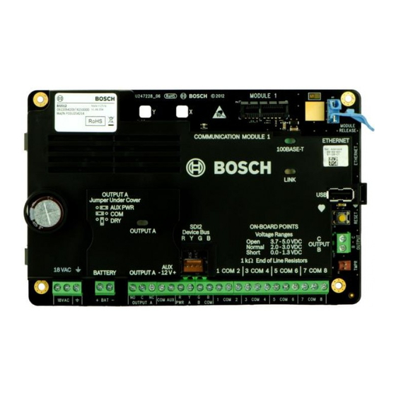
Page 77: Control Panel Board Overview
+ BAT - OUTPUT A PWR A B COM Figure 16.1: Control panel board overview (B5512 shown) Callout ᅳ Description For more information, refer to: 1 ᅳ Jumper to configure OUTPUT A Configure OUTPUT A using the jumper, page 25 2 ᅳ... - Page 78 Configure OUTPUT A using the jumper, page 25 19 ᅳ Battery terminals Secondary (DC) power, page 28 20 ᅳ 18 VAC power input terminals Primary (AC) power, page 28 2015.07 | 12 | F.01U.287.180 Installation and System Reference Guide Bosch Security Systems, Inc.
-
Page 79: System Wiring Diagrams
All terminals are supervised except OUTPUT A, OUTPUT B, and OUTPUT C. For proper supervision, do not loop wire under terminals. Break the wire run to provide supervision of connections. Bosch Security Systems, Inc. Installation and System Reference Guide 2015.07 | 12 | F.01U.287.180... - Page 80 18VAC + BAT - PWR A B COM OUTPUT A Figure 17.1: System wiring overview (B5512 shown) Callout ᅳ Description Callout ᅳ Description 1 ᅳ Control panel 8 ᅳ SDI2 wiring 2 ᅳ CX4010 UL Listed Class 2 Transformer 18 VAC 9 ᅳ...
-
Page 81: Battery Lead Supervision Wiring
18VAC + BAT - OUTPUT A PWR A B COM Figure 17.2: Battery lead supervision wiring (B5512 shown) Callout ᅳ Description 1 ᅳ D113 Battery Lead Supervision Module, if required 2 ᅳ Batteries 3 ᅳ To supervision point 4 ᅳ Control panel Bosch Security Systems, Inc. -
Page 82: 2-Wire Smoke Wiring (B201)
Control Panel 17.3 2-wire smoke wiring (B201) PASS-THRU SMOKE Figure 17.3: B201 to control panel wiring (B5512 shown) Callout ᅳ Description 1 ᅳ Control panel 2 ᅳ Interconnect cable 3 ᅳ B201 4 ᅳ 1 kΩ EOL resistor (P/N: F01U026703) (included with the control panel) 5 ᅳ... -
Page 83: 2-Wire Smoke Wiring (D125B)
LOOP 4, 5 7, 9 6, 8 Figure 17.4: D125B to control panel wiring (B5512 shown) Callout ᅳ Description Callout ᅳ Description 1 ᅳ Switched auxiliary power from the control panel’s 7 ᅳ Supervised smoke detector to A LOOP negative Output A (NC) 2 ᅳConnection from an on-board point on the control... - Page 84 | System wiring diagrams Control Panel Figure 17.5: Notification appliance circuit wiring (B5512 shown) Callout ᅳ Description 1 ᅳ Control panel 2 ᅳ Output jumper set to configure OUTPUT A terminal C for AUX POWER (jumper cover removed) 3 ᅳ D192G Notification Appliance Circuit module 4 ᅳ...
-
Page 85: Sdi2 Devices General System Wiring
End of Line Resistors 1 COM 2 3 COM 4 5 COM 6 7 COM 8 - 12 V + COM AUX PWR A B COM Figure 17.6: SDI2 devices system wiring (B5512 shown) Callout ᅳ Description B5512 B4512 B3512 Capacity Capacity Capacity 1 ᅳ... - Page 86 Control Panel You can wire modules via home run, daisy chain, or single level T-tap anywhere on the SDI2 bus. Figure 17.7: SDI2 bus wiring recommendations (B5512 shown) Callout ᅳ Description 1 ᅳ Control panel 2 ᅳ SDI2 device (module or keypad) 3 ᅳ...
- Page 87 CL2R, CL2X, signaling and power limited cables Belden 17.6 7500 1242 Belden 16.2 7000 5502 Belden 15.7 7350 5522 Belden 6363 5302 Belden 17.6 7500 1242 Bosch Security Systems, Inc. Installation and System Reference Guide 2015.07 | 12 | F.01U.287.180...
- Page 88 Fire alarm applications require NEC cable type FPLR, FPLP, or FPL or the equivalent power limited fire alarm cables (refer to article 760 of the NFPA 70 code). 2015.07 | 12 | F.01U.287.180 Installation and System Reference Guide Bosch Security Systems, Inc.
-
Page 89: Control Panel
Minimum system requirements for Classification in accordance with ANSI/SIA CP-01-2010 Bosch Security Systems, Inc. recommends testing the entire system UL Listed and Classified control unit Model B5512, B4512 or B3512; at least once a week, and having a qualified technician check UL Listed and Classified keypad Model B915, B920, B921C, B930, B942, or B942W the system at a minimum of once every 3 years. -
Page 90: Approved Applications
Approved applications The UL System Chart references the components that are evaluated and listed by UL for compatibility with B5512/B4512/B3512 control panels. These components meet the basic system requirements for the applicable standard. Refer to Compatible UL listed components, page 95. - Page 91 8 ᅳ Alarm input point 16 ᅳ Safe Use Terminals 1 through 8. (Select only one.) Use a D113 Battery Lead Supervision Module to supervise the battery connections Bosch Security Systems, Inc. Installation and System Reference Guide 2015.07 | 12 | F.01U.287.180...
- Page 92 B L K N/O 1 COMM 1 X1 - Figure 18.2: Detailed Rothenbuhler 5110_4001-42 High Security Bell to control panel wiring (B5512 shown) 1 ᅳ 5110 Logic Board 8 ᅳ Alarm input point* 2 ᅳ 4001-42 External Line Balancing Module 9 ᅳ...
-
Page 93: Fire Applications
Connect the smoke detectors to a suitable interface such as the B208 Octo-input Module or on-board point to meet UL and NFPA requirements. Notification Appliance Circuit (NAC) Refer to Notification appliance circuit wiring, page 83. Bosch Security Systems, Inc. Installation and System Reference Guide 2015.07 | 12 | F.01U.287.180... -
Page 94: Enclosures
Test Weekly: Perform a Fire Test weekly. According to UL 864, a Fire Test tests both the AC power and the battery. 18.1.4 Enclosures Mount the control panel assembly in any of the Bosch Security Systems, Inc. enclosures listed: – B10 Medium Control Panel Enclosure –... -
Page 95: Combination Fire And Intrusion Alarm Systems
Cellular Communicator B442 Conettix Plug-in Opt. Opt. Opt. Opt. Opt. Opt. Opt. Cellular Communicator B443 Conettix Plug-in Opt. Opt. Opt. Opt. Opt. Opt. Opt. Cellular Communicator Bosch Security Systems, Inc. Installation and System Reference Guide 2015.07 | 12 | F.01U.287.180... - Page 96 Enclosure D8108A Attack Resistant Opt. Opt. Opt. Opt. Opt. Opt. Enclosure or D8109 Fire Enclosure D8108A Attack Resistant Opt. Opt. Opt. Opt. Opt. Opt. Opt. Enclosure 2015.07 | 12 | F.01U.287.180 Installation and System Reference Guide Bosch Security Systems, Inc.
-
Page 97: Standby Battery Requirements And Calculations
Qty = ______ x Qty = ______ x Qty = ______ D125B ______ x Qty = ______ x Qty = ______ x Qty = ______ Bosch Security Systems, Inc. Installation and System Reference Guide 2015.07 | 12 | F.01U.287.180... - Page 98 Central Station (Bank) Central Station (Mercantile) Police Station Connected (Bank) 30 (CUL)/15 (UL) Police Station Connected (Mercantile) 30 (CUL)/15 (UL) Local Burglary (Bank) 30 (CUL)/15 (UL) 2015.07 | 12 | F.01U.287.180 Installation and System Reference Guide Bosch Security Systems, Inc.
-
Page 99: Household Fire Warning Equipment
The dispatch location of the law enforcement agency having jurisdiction over the protected property – A central station or residential monitoring station complying with the Standard for Central-Station Alarm Services, UL 827. Bosch Security Systems, Inc. Installation and System Reference Guide 2015.07 | 12 | F.01U.287.180... -
Page 100: Ul 636 - Holdup Alarm Units And System
Set Area # Delay Restorals as follows: – Area # Delay Restorals = No (Restoral report is sent when point restores.) 18.7 Conduct testing monthly, with the primary de-energized. 2015.07 | 12 | F.01U.287.180 Installation and System Reference Guide Bosch Security Systems, Inc. -
Page 101: Keypad Installer Menu
0, and then connect it to the control panel. Use the control panel RESET button to enter SERVICE MODE. The rate of flashing of the Heartbeat LED increases while in SERVICE MODE. Bosch Security Systems, Inc. Installation and System Reference Guide 2015.07 | 12 | F.01U.287.180... - Page 102 3 COM 4 5 COM 6 7 COM 8 Figure 19.1: RESET button and Heartbeat LED location (B5512 shown) Accessing SERVICE MODE (rapid pulsing Heartbeat LED): Press and hold the control panel RESET button until the Heartbeat LED flashes fast. The keypad shows SERVICE MODE and prompts for the installer passcode.
- Page 103 Srvc Byp menu Plug-in Module Versions menu Enable Status Setup Set License Status Set Remote ID Cloud menu View Settings Exit Figure 19.2: Keypad installer menu tree Bosch Security Systems, Inc. Installation and System Reference Guide 2015.07 | 12 | F.01U.287.180...
- Page 104 All On menu <All On Delay <All On Instant <All On Select Area *As configured by your security company. ^B94x only. Figure 19.3: B93x/B94x keypads Main menu tree 2015.07 | 12 | F.01U.287.180 Installation and System Reference Guide Bosch Security Systems, Inc.
- Page 105 Press 4 for show date/time keypad config Press 5 for default text *As configured by your security company. Figure 19.4: B91x/B92x keypads Main menu tree Bosch Security Systems, Inc. Installation and System Reference Guide 2015.07 | 12 | F.01U.287.180...
- Page 106 Use [PREV] or [NEXT] to cycle through the characters. Press [ENTER] to choose the character shown. Network address characters Use the [0] key to enter a period or dash. 2015.07 | 12 | F.01U.287.180 Installation and System Reference Guide Bosch Security Systems, Inc.
-
Page 107: Program Menu
Press [ENTER] to edit the phone destination and then press [NEXT] to go to the format option. Press [ENTER] to edit the phone format for the selected destination. Bosch Security Systems, Inc. Installation and System Reference Guide 2015.07 | 12 | F.01U.287.180... -
Page 108: Reporting > [2] Network Menu Parameters
[Edit] to edit the enhanced communication option. Press the icon or softkey for the desired option. Press [Save] to save the programming. When the keypad shows Parameter Saved, escape from the menu. 2015.07 | 12 | F.01U.287.180 Installation and System Reference Guide Bosch Security Systems, Inc. - Page 109 Go to [1] Program > [1] Reporting > [2] Network > [2] Enhanced Comm Parms. The keypad shows the network address for the selected Enhanced Comm destination. Bosch Security Systems, Inc. Installation and System Reference Guide 2015.07 | 12 | F.01U.287.180...
-
Page 110: Reporting > [3] Routing Menu Parameters
Step 8. Delete existing characters, if necessary, and then enter the new number. Press [ENTER] to save the change, and then escape from the menu. 2015.07 | 12 | F.01U.287.180 Installation and System Reference Guide Bosch Security Systems, Inc. - Page 111 Use [PREV] or [NEXT] to scroll though the list of devices (for destination 1) and go to the destination 1 option you want to select for the current device (for example, Phone 1). Bosch Security Systems, Inc. Installation and System Reference Guide...
-
Page 112: Reporting > [4] Personal Note Menu Parameters
When the keypad shows Parameter Saved, escape from the menu. B93x/B94x keypads configuration of SMS Phone # Enter the installer passcode, and then open the [1] Installer menu. 2015.07 | 12 | F.01U.287.180 Installation and System Reference Guide Bosch Security Systems, Inc. -
Page 113: Network > [1] Ethernet > (Choose The Bus Module Or On-Board) > [1] Module
Press [Yes] or [No] – whichever is available – to change the programming. Press [Save] to save the programming. When the keypad shows Parameter Saved, escape from the menu. UPnP Enable Bosch Security Systems, Inc. Installation and System Reference Guide 2015.07 | 12 | F.01U.287.180... -
Page 114: Network > [1] Ethernet > (Choose The Bus Module Or On-Board) > [2] Address
Go to [1] Program > [2] Network > [1] Ethernet > (choose the bus module or on-board) > [2] Address Parameters > [2] Subnet Mask. Press [ENTER] to edit the subnet mask address. 2015.07 | 12 | F.01U.287.180 Installation and System Reference Guide Bosch Security Systems, Inc. - Page 115 Delete the existing number, if necessary, and then enter the new number. Press [ENTER] to save the programming. When the keypad shows Parameter Saved, escape from the menu. Bosch Security Systems, Inc. Installation and System Reference Guide 2015.07 | 12 | F.01U.287.180...
-
Page 116: Network > [1] Ethernet > (Choose The Bus Module Or On-Board) > [3] Dns
Delete the existing number, if necessary, and then enter the new number. Use [PREV] or [NEXT] to move to a different byte. Press [ENTER] to save the programming. When the keypad shows Parameter Saved, escape from the menu. 2015.07 | 12 | F.01U.287.180 Installation and System Reference Guide Bosch Security Systems, Inc. -
Page 117: Network > [2] Cellular > (Choose The Sdi2 Cellular Module Or Plug-In Module)
SIM Passcode _______________________________ _______________________________ SIM PIN _______________________________ _______________________________ SIM APN B91x/B92x keypads configuration of SIM APN Enter the installer passcode, and then open the [1] Installer menu. Bosch Security Systems, Inc. Installation and System Reference Guide 2015.07 | 12 | F.01U.287.180... - Page 118 When the keypad shows Parameter Saved, escape from the menu. B93x/B94x keypads configuration of SIM Passcode Enter the installer passcode, and then open the [1] Installer menu. 2015.07 | 12 | F.01U.287.180 Installation and System Reference Guide Bosch Security Systems, Inc.
-
Page 119: Rps > [1] Rps Passcode Menu Parameters
Delete existing characters, if necessary, and then enter the new characters. Press [Save] to save the programming. When the keypad shows Parameter Saved, escape from the menu. Bosch Security Systems, Inc. Installation and System Reference Guide 2015.07 | 12 | F.01U.287.180... -
Page 120: Rps > [2] Rps Phone Number Menu Parameters
For a hostname, press a number key repeatedly to scroll through the number and letters shown on the key. Press [Save] to save the programming. 2015.07 | 12 | F.01U.287.180 Installation and System Reference Guide Bosch Security Systems, Inc. -
Page 121: Rps > [4] Rps Port Number Menu Parameters
Use [PREV] or [NEXT] to toggle between Yes and No. Press [ENTER] while viewing the desired option to save the programming. When the keypad shows Parameter Saved, escape from the menu. Bosch Security Systems, Inc. Installation and System Reference Guide 2015.07 | 12 | F.01U.287.180... -
Page 122: Keypad Menu Parameters
Keypad 5 No Device / Area Wide / Acct Wide / Panel Wide Keypad 6 No Device / Area Wide / Acct Wide / Panel Wide 2015.07 | 12 | F.01U.287.180 Installation and System Reference Guide Bosch Security Systems, Inc. -
Page 123: Users Menu Parameters
To add and remove users, change users passcodes, and perform other user functions from the keypad, you must use the Users menu from the Main menu. Refer to the Control Panels (B9512G/B8512G/B5512/B4512/B3512) Owner’s Manual for more information. Users (In the Installer menu) B91x/B92x keypads configuration of Users Enter the installer passcode, and then open the [1] Installer menu. -
Page 124: Points Menu Parameters
__ __ __ __ __ __ __ __ __ ____ USER __ __ * Applicable to B5512 only. 19.1.16 [7] Points menu parameters Use the parameters in this menu to assign a Point Source and a Point Index to each point. - Page 125 _(30)_ Entry Tone Off Silent Bell Ring Until Restored Audible After Two Fails Invisible Point Buzz on Fault __(0)__ __(0)__ __(0)__ __(0)__ __(0)__ __(0)__ __(0)__ __(0)__ Bosch Security Systems, Inc. Installation and System Reference Guide 2015.07 | 12 | F.01U.287.180...
- Page 126 00:00 00:00 00:00 00:00 Delay Response Disarmed 00:00 00:00 00:00 00:00 00:00 00:00 00:00 00:00 Delay Response Armed 00:00 00:00 00:00 00:00 00:00 00:00 00:00 00:00 2015.07 | 12 | F.01U.287.180 Installation and System Reference Guide Bosch Security Systems, Inc.
- Page 127 __(0)__ __(0)__ __(0)__ __(0)__ Display as Device Local While Disarmed Local While Armed Disable Restorals FA Returnable Bypass Returnable Bypassable Swinger Bypass Report Bypass at Occurrence Bosch Security Systems, Inc. Installation and System Reference Guide 2015.07 | 12 | F.01U.287.180...
- Page 128 00:00 00:00 00:00 00:00 Delay Response Disarmed 00:00 00:00 00:00 00:00 00:00 00:00 00:00 00:00 Delay Response Armed 00:00 00:00 00:00 00:00 00:00 00:00 00:00 00:00 2015.07 | 12 | F.01U.287.180 Installation and System Reference Guide Bosch Security Systems, Inc.
- Page 129 Local While Disarmed Local While Armed Disable Restorals FA Returnable Bypass Returnable Bypassable Swinger Bypass Report Bypass at Occurrence Y/N Defer Bypass Report Cross Point Alarm Verify Resettable Bosch Security Systems, Inc. Installation and System Reference Guide 2015.07 | 12 | F.01U.287.180...
- Page 130 Custom Function Disabled Disabled Disabled Disabled Monitor Delay 00:00 00:00 00:00 00:00 Delay Response Disarmed 00:00 00:00 00:00 00:00 Delay Response Armed 00:00 00:00 00:00 00:00 2015.07 | 12 | F.01U.287.180 Installation and System Reference Guide Bosch Security Systems, Inc.
- Page 131 __ __ __ __ __ __ __ __ __ __ __ __ __ __ __ __ __ __ __ __ __ __ __ __ __ __ __ Bosch Security Systems, Inc. Installation and System Reference Guide 2015.07 | 12 | F.01U.287.180...
- Page 132 Press [Source] to view and edit the source, and then press [Edit] to edit the source. /[PREV] or /[NEXT] to scroll through the available options. Press [Save] to save the programming. When the keypad shows Parameter Saved, escape from the menu. 2015.07 | 12 | F.01U.287.180 Installation and System Reference Guide Bosch Security Systems, Inc.
-
Page 133: Disable Programming Menu
Press [ENTER] to disable keypad programming, and then press [NEXT] to go to the No option. Press [ENTER] to save the programming. When the keypad shows Parameter Saved, escape from the menu. Bosch Security Systems, Inc. Installation and System Reference Guide 2015.07 | 12 | F.01U.287.180... -
Page 134: Wireless Menu
Verify the RFID shown on the keypad matches the RFID label on the activated device. 19.2.2 [1] RF Point Menu> [2] Replace Point RFID In this menu, you can replace RFID points. Replace Point RFID 2015.07 | 12 | F.01U.287.180 Installation and System Reference Guide Bosch Security Systems, Inc. -
Page 135: Rf Point Menu> [3] Remove Point Rfid
Point RFID Removed. Escape from the menu. 19.2.4 [2] RF Repeater Menu > [1] Add Repeater In this menu, you can add Repeater points. Add Repeater Bosch Security Systems, Inc. Installation and System Reference Guide 2015.07 | 12 | F.01U.287.180... -
Page 136: Rf Repeater Menu > [2] Replace Repeater
Initiate discovery on a RADION device per the device instructions, or press the RESET button on an Inovonics device. When the keypad shows Repeater Replaced, escape from the menu. 2015.07 | 12 | F.01U.287.180 Installation and System Reference Guide Bosch Security Systems, Inc. -
Page 137: Rf Repeater Menu > [3] Remove Repeater
Press [State] to view the state. The menu scrolls through the following sub-categories, with the results of the diagnostic check: State, Tamper, Low-Battery, Maintenance. When finished viewing the information, escape from the menu. Signal Strength (for RF points) Bosch Security Systems, Inc. Installation and System Reference Guide 2015.07 | 12 | F.01U.287.180... -
Page 138: Rf Diagnostic Menu > [2] Rf Repeater Menu
Enter the installer passcode, and then open the [1] Installer menu. Go to [2] Wireless > [3] RF Diagnostic Menu > [2] RF Repeater Menu > [1] Strength. 2015.07 | 12 | F.01U.287.180 Installation and System Reference Guide Bosch Security Systems, Inc. -
Page 139: Diags Menu
Link, IP Address, DNS, WAN IPv4, WAN IPv6, LAN IPv4, LAN IPv6. When finished viewing the information, escape from the menu. Bosch Security Systems, Inc. Installation and System Reference Guide 2015.07 | 12 | F.01U.287.180... -
Page 140: Cellular Menu
– Model (The cellular radio model.) – Version (The cellular radio version.) When finished viewing the information, escape from the menu. 19.3.4 [4] IP Camera IP Camera 2015.07 | 12 | F.01U.287.180 Installation and System Reference Guide Bosch Security Systems, Inc. -
Page 141: Serv Byp (Service Bypass) Menu
Use the Versions menu to view control panel version information. Versions B91x/B92x keypads use of Versions Enter the installer passcode, and then open the [1] Installer menu. Go to [5] Versions. Bosch Security Systems, Inc. Installation and System Reference Guide 2015.07 | 12 | F.01U.287.180... - Page 142 Go to [5] Versions. Press the icon or softkey for the item for which you want view the version. The keypad shows the version. Escape from the menu. 2015.07 | 12 | F.01U.287.180 Installation and System Reference Guide Bosch Security Systems, Inc.
-
Page 143: Cloud Menu
Use this menu to enable the Cloud connection, and to view and edit the control panel Cloud settings for: Value License (assigned by Bosch) _____________________________________________ Remote ID (assigned by Bosch) _____________________________________________ Product ID (for Remote Security _____________________________________________ Certificate Builder) Set Enable Status B91x/B92x keypads use of Set Enable Status Enter the installer passcode, and then open the [1] Installer menu. -
Page 144: Status
Go to [1] Program > [6] Cloud > [2] Status. The keypad shows the status (Not connected, Connected, Trying to connect, or Unreachable). When finished, escape from the menu. 2015.07 | 12 | F.01U.287.180 Installation and System Reference Guide Bosch Security Systems, Inc. -
Page 145: Specifications
Humidity Arming stations B915 Basic Keypads, B920 Two-line Alphanumeric Keypads (SDI2), B921C Two-line Alphanumeric Keypads (SDI2), B930 ATM Style Alphanumeric Keypads (SDI2), B942/B942W Touch Screen keypads Bosch Security Systems, Inc. Installation and System Reference Guide 2015.07 | 12 | F.01U.287.180... - Page 146 Short circuit current - 5 mA Compatible B10 Medium Control Panel Enclosure, B11 Small Control Panel Enclosure, D2203 enclosures Enclosure, D8103 Universal Enclosure, D8108A Attack Resistant Enclosure, and D8109 Fire Enclosure 2015.07 | 12 | F.01U.287.180 Installation and System Reference Guide Bosch Security Systems, Inc.
-
Page 147: Wire Requirements
18 AWG min (up to 12 AWG max) Earth ground 16 AWG min (up to 14 AWG max) BAT + Battery + Bosch supplied wire lead, included with control panel. BAT - Battery - OUTPUT A NO Output A normally open... -
Page 148: Reporting And Device Number Information
NsD52 Nriaa/idiiiiTZ Local Only Local Only Area Watch Start NsD51 Nriaa/idiiiiTW Local Only Local Only Armed PartOn delay Csiiii Nriaa/idiiiiNL Armed STAY 3 441 aa uuu 2015.07 | 12 | F.01U.287.180 Installation and System Reference Guide Bosch Security Systems, Inc. - Page 149 Closing Late by Area Csiiii Nriaa/idiiiiCJ Late O/C 3 452 aa uuu Communication failure by TsB01 NrggYC Failure to communicate 1 354 00 000 route group event Bosch Security Systems, Inc. Installation and System Reference Guide 2015.07 | 12 | F.01U.287.180...
- Page 150 System Peripheral Trouble 1 330 00 Equipment Restore RsD29 NpiddddIR System Peripheral Trouble 3 330 00 Restore Event Log Overflow AsD01 Event Log Overflow 1 624 00 000 2015.07 | 12 | F.01U.287.180 Installation and System Reference Guide Bosch Security Systems, Inc.
- Page 151 3 380 aa ppp Gas Trouble Tpppp NriaaGTpppp Sensor Trouble 1 380 aa ppp Gas Trouble Restore Rpppp NriaaGJpppp Sensor Trouble Restore 3 380 aa ppp Bosch Security Systems, Inc. Installation and System Reference Guide 2015.07 | 12 | F.01U.287.180...
- Page 152 1 330 00 zzz Non-Fire Cancel Alarm \siiii Nriaa/idiiiiBC Cancel 1 406 aa uuu Normal start-up of the NsD14 System Reset 1 305 00 000 control panel 2015.07 | 12 | F.01U.287.180 Installation and System Reference Guide Bosch Security Systems, Inc.
- Page 153 Local Only (Assign Card Event) Replace Sensor Tpppp NriaaBTpppp Maintenance Alert 1 393 aa ppp Replace Sensor Restore Rpppp NriaaBRpppp Maintenance Alert Restore 3 393 aa ppp Bosch Security Systems, Inc. Installation and System Reference Guide 2015.07 | 12 | F.01U.287.180...
- Page 154 1 312 00 SDI Device Over Current RsssD PS Over Current Restore 3 312 00 Restore SDI Device Tamper TsssD Exp. Module Tamper 1 341 00 2015.07 | 12 | F.01U.287.180 Installation and System Reference Guide Bosch Security Systems, Inc.
- Page 155 Status: Fire Trouble SGpppp OriaaFTpppp Status: Gas Alarm SApppp NriaaGAppp Status: Gas Supervisory SJpppp NriaaGSppp Status: Gas Trouble STpppp NriaaGTppp Status: Open by Area SOssss OriaOP Bosch Security Systems, Inc. Installation and System Reference Guide 2015.07 | 12 | F.01U.287.180...
-
Page 156: Sdi2 Address Information
All point numbers, user ID’s, output numbers, and device identifier numbers are formatted as 4-digit numbers (right justified with zeros) when transmitted from the control panel in Modem4 format. 2015.07 | 12 | F.01U.287.180 Installation and System Reference Guide Bosch Security Systems, Inc. -
Page 157: Device Numbers (Zzz, Dddd)
To better identify the originator of some control panel events with no unique, Standard User identified, special user IDs designate each special case. All user ID are defined in the table below. Bosch Security Systems, Inc. Installation and System Reference Guide 2015.07 | 12 | F.01U.287.180... -
Page 158: Keypad Alarm Virtual Point Numbers (Ppp, Pppp)
3.01 and higher, reported point number reported point number Keypad 1 Keypad 2 Keypad 3 Keypad 4 Keypad 5 Keypad 6 Keypad 7 Keypad 8 2015.07 | 12 | F.01U.287.180 Installation and System Reference Guide Bosch Security Systems, Inc. - Page 160 Bosch Security Systems, Inc. Bosch Sicherheitssysteme GmbH 130 Perinton Parkway Robert-Bosch-Ring 5 Fairport, NY 14450 85630 Grasbrunn Germany www.boschsecurity.com © Bosch Security Systems, Inc., 2015...
Need help?
Do you have a question about the B5512 and is the answer not in the manual?
Questions and answers