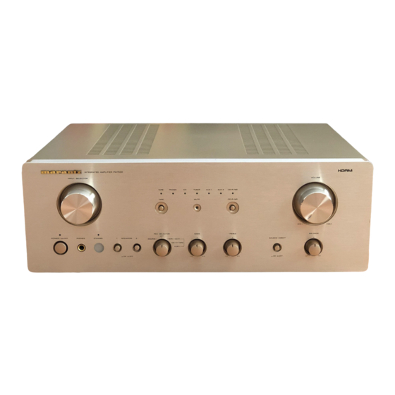
Marantz PM7000 User Manual
Marantz integrated amplifier user guide pm7000
Hide thumbs
Also See for PM7000:
- Service manual (29 pages) ,
- User manual (16 pages) ,
- Specification sheet (2 pages)
Table of Contents
Advertisement
Advertisement
Table of Contents

Summary of Contents for Marantz PM7000
- Page 1 Model PM7000 User Guide Integrated Amplifier...
- Page 2 CONTENTS Engligh ... page 6 Français ...page 15...
- Page 3 CAUTION RISK OF ELECTRIC SHOCK DO NOT OPEN CAUTION: TO REDUCE THE RISK OF ELECTRIC SHOCK, DO NOT REMOVE COVER (OR BACK) NO USER-SERVICEABLE PARTS INSIDE REFER SERVICING TO QUALIFIED SERVICE PERSONNEL The lightning flash with arrowhead symbol, within an equilateral triangle, is intended to alert the user to the presence of uninsulated "dangerous voltage"...
- Page 4 This product was designed and manufactured to meet strict quality and safety standards. There are, however, some installation and operation precautions which you should be particularly aware of. 1. Read Instructions — All the safety and operating instruc- tions should be read before the appliance is operated. 2.
- Page 5 EXAMPLE OF ANTENNA GROUNDING ACCORDING TO NATIONAL ELECTRICAL CODE INSTRUCYIONS CONTAINED IN ARTICLE 810 -"RADIO AND TELEVISION EQUIPMENT" NOTE TO CATV SYSTEM INSTALLER: This reminder is provided to call the CATV (Cable-TV) system installer's attention to Article 820-40 of the NEC, which provides guidelines for proper grounding and, in particular, specifies that the cable ground shall be connected to the grounding system of the building, as close to the point of cable entry as practical.
- Page 6 — Should foreign matter or water get into the interior of the amplifier, immediately turn it off and contact your original dealer or Marantz service provider. — Never pull on the mains lead when unplugging the amplifier. Grasp the plug itself.
- Page 7 CONTROLS, CONNECTORS, AND INDICA- TORS (Figure 2) Remote Control Bus Terminals (REMOTE CONT. BUS) These terminals can used to connect other audio equipment that is equipped with a remote control bus terminal. Connection requires a special cable. The bus OUT terminal sends signal to the connected equipment, while the bus IN terminals receive signals.
- Page 8 Standby Indicator This indicator is lit while the amplifier is in the Standby Mode. Pressing the remote control unit’s POWER buttons switches the amplifier between standby and power on. OPERATION INTEGRATED AMPLIFIER PM7000 INPUT SELECTOR TAPE PHONO TUNER AUX1...
- Page 9 TAPE DECK CD-R/MD OPERATION INTEGRATED AMPLIFIER PM7000 INPUT SELECTOR TAPE PHONO TUNER AUX1 AUX2 CD-R/MD TAPE MUTE CD-R/MD REC SELECTOR BASS TREBLE POWER ON/OFF PHONES STANDBY SPEAKERS SOURCE TAPE CD-R CD-R TAPE COPY PERFORM THE APPLICABLE OPERATION ON THE CONNECTED TAPE DECK.
- Page 10 REMOTE CONTROL UNIT RC 8000PM The RC8000PM remote control unit can be used to control any Marantz AV equipment that has a remote sensor, as well as other Marantz equipment connected to the main equipment’s remote control bus. The buttons of the remote control unit are arranged on the control panel according to functional groups as shown in the illustration below.
- Page 11 CD-R BUTTON The following are the functions assigned to control buttons after the CD-R amplifier source button is pressed. BUTTON NAME FUNCTION Play Fast-forward Fast-reverse None Stop Pause OPEN/CLOSE Open/close Next track – Previous track A, F/P None B, -/-- None MODE Auto Music Scan (AMS)
-
Page 12: Using The Remote Control Unit
(2) Load two batteries, making sure their positive (+) and negative (–) ends are facing correctly. Two AA-size (R6) (UM-3) batteries (3) Slide the battery compartment cover back into place and press until it clicks shut. Amplifier (PM7000) Back of Remote Control Unit (RC8000PM) -
Page 13: Care And Maintenance
4. Dry the amplifier by wiping it with a soft dry cloth. REPAIRS Only the most competent and qualified serviced technicians should be allowed to service this amplifier. Marantz and its factory-trained warranty personnel have the special knowledge and facilities required for the repair and calibration of this amplifier. - Page 14 MODEL PM7000 TECHNICAL SPECIFICATIONS Power output RMS 8 ohms (20 Hz-20 kHz) ... 95 W DIN 8 ohms ... 105 W THD at 8 ohms RMS rated output ... 0.03% Damping factor ... 150 IHF dynamic power 8 ohms ... 120 W Magnetic cartridge input Input sensitivity impedance ...
- Page 15 FIGURES Tuner Output CD player SYSTEM 2 SYSTEM 1 Processor Input Output PROCESSOR CD-R/MD AUX2 TAPE AUX1 TUNER PHONO NOTE: Turn the knobs on the speaker terminals by hand. (Do not use a tool to turn the knobs.) Loosen the terminal Figure 1 Tape Deck Output...
- Page 16 PROCESSOR CD-R/MD AUX2 TAPE AUX1 TUNER PHONO INTEGRATED AMPLIFIER PM7000 INPUT SELECTOR POWER ON/OFF PHONES STANDBY SPEAKER SYSTEMS SYSTEM 1 : MINMUM 8 OHMS SYSTEM 2 : MINMUM 8 OHMS SYSTEM 1 AND 2 : MINMUM 16 OHMS – –...
- Page 17 78 The Strand, Sliema SLM07, Malta P.O. Box 685, Bell Village, Port Louis, Mauritius A division of Marantz Europe B.V., Building SFF-2, P.O. Box 80002, 5600 JB Eindhoven, The Netherlands 4 Station Street, Thornleigh NSW 2120, Australia Lillegrensen 7, N-0159 Oslo, Norway P.O.


Need help?
Do you have a question about the PM7000 and is the answer not in the manual?
Questions and answers