
Related Manuals for Pisector GSM-01


Summary of Contents for Pisector GSM-01
- Page 1 Wireless GSM Alarm System (GSM-01) User Manual Profile For a better understanding of this product, please read this user manual thoroughly before using it.
- Page 2 Features GSM 900/1800/1900 bands, can be used all over the world. 3 zones for wired detectors and 16 zones for wireless detectors. Set arm, disarm, emergency alarm by remote controller. Set arm, disarm, monitor, output by calling the host. Set arm, disarm, monitor, output by sending SMS. Monitor environment on the spot.
- Page 3 Installation Host Insert SIM card in alarm system Press the yellow point on the unit with a pencil tip or other tools, SIM card tray will come out. Put the SIM card into the tray and make sure the Metal contacts of the card to be downwards, and then push the tray back.
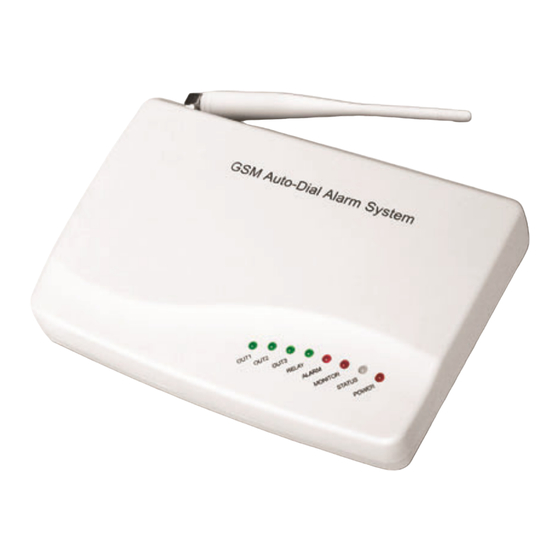
- Page 4 LED status explanation LED Status System working status Hasn’t turned on the switch; hasn’t connected the power; no power in built-in POWER battery power supply is normal Ready to code wireless sensors Orange (flash slowly) Check SIM card and search GSM network Power SIM card and GSM signal are normal;...
- Page 5 I1, I2, I3: Connect wired sensors Three inputs are available to connect wired sensors. Inputs are independent and not coded as different zones. When these sensors are triggered, the unit will sent SMS message: Wire Activate (1~3). Sensors can be NO (normally Open) or NC (normally Close) type. More than 1 sensor can be connected to one input: connect their alarm contacts in series.
- Page 6 O3 (SPEAKER): This port is for voice output, it can be connected to the speaker. The other port of the speaker is to connect to ground. You can control it by call in or send the SMS. RELAY1, RELAY2: These two ports will close 3 minutes when alarm happens. You can use these two ports to start the power supply of the camera when alarm happens, also you can disable this function by setting command 16#1#, you can also make this relay close or open anytime by sending SMS or...
- Page 7 Door sensor Door sensors are used for detecting the status of open and close of windows and doors. It will detect it and send the signal to main panel. Tear apart the double-side adhesive tape on the magnet and the transmitter.
- Page 8 III. Set alarm phone numbers You can send message to the unit to set 5 alarm phone numbers and 7 alarm SMS. The command format: password #operation code # content # 1. Save the alarm phone numbers. 123456#5X# alarm phone numbers #. (X = 1 to 5) Save 5 group alarm phone numbers into the base.
- Page 9 You can send SMS commands to rewrite the above 7 kinds of SMS contents, every SMS cannot excess 24 English characters. 123456#8X# SMS content #. (X = 1 to 5) For example: Rewrite the 1 SMS content into “Middle door open”: 123456#81#Middle door open# Rewrite the 6 to 16...
- Page 10 the phone (not need input password) to operate it, press 3# 1# to start the siren and press 3# 0# to stop it; press 4# 1# to listen-in and press 4# 0# to stop it; press 93# 1# to talk with the spot and press 93# 0# to stop it.
- Page 11 Commands table: Function Function 1#1# Out arm* 1#2# Home arm (all detectors work) (part detectors work) 1#0# Disarm*(all detectors not work) 3#1# Siren Sounds 3#0# Stop sounding immediately 4#1# Start listen-in* Call the 4#0# Stop listen-in alarm panel and then Call the alarm panel and then input this command input this command...
- Page 12 27#(00- Arm delay, 00-99: delay time (default: 10sec) 99)# 28#(00- Alarm delay, 00-99: delay time (default: 00) 99)# 30## show the arm and disarm status of every zone (SMS command applicable only) 31#--# Change password. Enter a new password (1—6 bit). 38#--# Set arm of zone independently (wireless zone: 1—16;...
- Page 13 87#--# Wired zone Message(0-24bit) 90## Show Output status in the host 91#1# Set Output 1 to high 91#0# Set Output 1 change to low 92#1# Set Output 2 to high 92#0# Set Output 2 change to low 93#1# Set talk to the host 93#0# talk host...
- Page 14 successful, a long beep shows the sentence you input is successful, two short beeps shows your input is failed, you should try again. In the above SMS operation, you will receive a reply message for confirmation after you send the message command to the base, the replied message for example: Disarm, Sms: ON, Phone: ON, Siren: ON, Center Tel: OFF, Arm Center Tel: OFF, Disarm Center Tel: OFF...
- Page 15 Press the “Out Arm ” button on the remote controller, the STATUS indicator on the main panel flashes in orange; 10 seconds later, it will turn green with slow flash. The system enters Out Arm mode, and all the detectors will be in working status. Home Arm: Press the “Home Arm ”...
- Page 16 VII. Add more detectors You can add new sensors or detectors, such as wireless door sensors, PIR Sensors, gas and smoke detectors into the unit. 1) Add sensors ready to work when you set both Out Arm and Home Arm: When the GSM host begins to be powered on, the status LED light on panel will be red for 20 seconds, this is code learning mode.
- Page 17 panel changes to orange to search for GSM network, then to green. Note: If there were 4 wireless sensors in the host, they stand for zone 1 to zone 4, and then the new added sensor will be 5th zone in the host. VIII.
- Page 18 The following sensors are optional: Optional sensors/detectors are packed separately. You can choose according to your specific requirements.
- Page 19 TECHNICAL PARAMETERS Main Panel Static current: 20mA Power: 9V-12V DC Working temperature:-10 ~ +40 GSM: 900/1800/1900MHz band Receiving code: ASK Frequency: 433MHZ Wireless distance: 100 M Wireless detectors: 16 Wire detectors: 3 Wireless Gap Detector (Door/ Window Contact) Power Supply: DC12V (inner 7.4V battery) Static Current: ≤20 uA Transmission Current: ≤15mA Transmission Frequency: 433MHZ±0.5MHZ...
- Page 20 Wireless PIR Detector Power Supply: DC9V (inner 9V battery) Static Current: ≤100 uA Transmission Current: ≤20mA Transmission Frequency: 433MHZ±0.5MHZ Transmission Distance: No obstacle 80m Detective Speed: 0.3 - 3m/s Detective Distance: 5 - 12m Detective Range: Horizontal 110° Vertical 60° Working Condition: Temperature –10 ~+ 40 Humidity ≤...
- Page 21 Problems Causes Solutions Arm the unit Hasn’t armed Operate after 30 Less than 30 seconds seconds after arming Set the number Set wrong phone again according number to the manual Cannot alarm by phone The two parts of Adjust the door/window sensor is installation place installed too far from...
- Page 22 1. Low power battery in the accessory 1. Replace the battery 2. There is block between the 2. Pull out the antenna The main panel cannot control panel and the of the accessory and receive signals from the wireless accessory or the the main panel, and accessory distance between them is...
Need help?
Do you have a question about the GSM-01 and is the answer not in the manual?
Questions and answers