Lopi Answer Owner's Manual
Residential freestanding stove
• mobile-home freestanding stove
• alcove approved
• masonry fireplace insert
• zero clearance (metal) fireplace insert
Hide thumbs
Also See for Answer:
- Owner's manual (48 pages) ,
- Manual (48 pages) ,
- Owner's manual (44 pages)
Table of Contents
Advertisement
SAFETY NOTICE:
If this appliance is not properly installed, a house
fire may result. For your safety, follow the
installation directions. Contact local building or
fire officials about restrictions and installation
inspection requirements in your area.
Answer Wood Stove & Insert
10850 117th Place N.E. Kirkland, WA 98033
Part # 93508037
Answer
Owner's Manual
¥ Residential Freestanding Stove
¥ Mobile-Home Freestanding Stove
¥ Alcove Approved
¥ Masonry Fireplace Insert
¥ Zero Clearance (Metal) Fireplace Insert
$10.00
- April, 2001 -
Listed
Advertisement
Table of Contents
Troubleshooting

Related Manuals for Lopi Answer


Summary of Contents for Lopi Answer
-
Page 1: Safety Notice
For your safety, follow the installation directions. Contact local building or fire officials about restrictions and installation inspection requirements in your area. Answer Wood Stove & Insert Listed 10850 117th Place N.E. Kirkland, WA 98033 Part # 93508037... -
Page 3: Introduction & Important Information
Answer you have joined the growing ranks of concerned individuals whose selection of an energy system reflects both a concern for the environment and aesthetics. The Lopi Answer is one of the finest appliances the world over. This manual will explain the installation, operation, and maintenance of this appliance. -
Page 4: Safety Precautions
AFETY RECAUTIONS ¥ The viewing door must be ¥ Gasoline or other closed and latched during flammable liquids must operation. never be used to start the fire or "Freshen Up" the ¥ Never block free airflow fire. Do not store or use through the air vents on gasoline or other this appliance. - Page 5 AFETY RECAUTIONS ONTINUED ¥ Never try to repair or ¥ Do not make any changes replace any part of this or modifications to an appliance unless existing masonry fireplace instructions are given in or chimney to install this this manual. All other appliance.
-
Page 6: Table Of Contents
ABLE OF ONTENTS General Information Operating Your Appliance (Continued) Introduction & Important Information......1 Blower Operation ............24 Safety Precautions............. 2 When to turn the blower on ........24 Features & Specifications ........... 5 Blower controls ............. 24 How to Use the Blower to Regulate Heat ..... 24 Stove Installation A Word about Wood ........... -
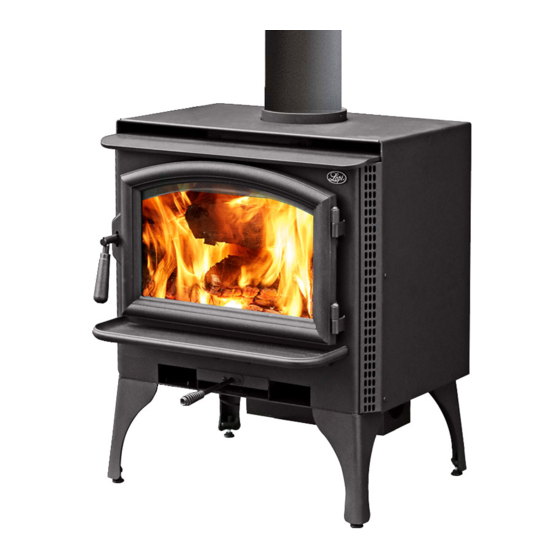
Page 7: Features & Specifications
EATURES AND PECIFICATIONS Installation Options: Features: ¥ Freestanding ¥ EPA Phase II Approved ¥ 1.6 Cubic Foot Firebox Volume ¥ Freestanding in an Alcove ¥ Single, Push/Pull Operating Control ¥ Freestanding in a Mobile Home ¥ Accepts Logs Up to 18" Long ¥... -
Page 8: Stove Installation
TOVE NSTALLATION SAFETY NOTICE: If this appliance is not properly installed, a house fire may result. For your safety, follow the installation directions. Contact local building or fire officials about restrictions and installation inspection requirements in your area. ¥ Check with local building officials for any permits required for installation of this stove and notify your insurance company before proceeding with installation. -
Page 9: Stove Placement Requirements
TOVE NSTALLATION TOVE LACEMENT EQUIREMENTS HINT: REDUCING CLEARANCES - Clearances may be reduced by methods specified in NFPA 211, listed wall shields, pipe shields, or other means approved by local building or fire officials. ¥ Stove must be placed so that no combustibles are within, or can swing within (e.g. drapes, doors), 36"... -
Page 10: Optional Equipment Requirements
TOVE NSTALLATION PTIONAL QUIPMENT EQUIREMENTS (See "Optional Equipment" starting on page 36 ¥ Must be installed with either the optional legs or pedestal ACTORY UILT HIMNEY EQUIREMENTS ¥ Chimney connector must be a minimum 24 MSG black or 26 MSG blued steel ¥... -
Page 11: Chimney Termination Requirements
TOVE NSTALLATION HIMNEY ERMINATION EQUIREMENTS ¥ Must have an approved cap (to prevent water from entering) ¥ Must not be located where it will become plugged by snow or other material ¥ Must terminate at least 3' above the roof and at least 2' above any portion of the roof within 10' Chimney must extend 2' Slanted Roofs above any portion of the roof... -
Page 12: Alcove Installation Requirements
TOVE NSTALLATION LCOVE NSTALLATION EQUIREMENTS Whenever the stove is placed in a location where the ceiling height is less than 7' tall, it is considered an alcove installation. Because of the reduced height, the special installation requirements listed below must be met. ¥... -
Page 13: Mobile Home Requirements
NSTALLATION OBILE EQUIREMENTS The Answer is approved for installation into a mobile home if the requirements listed below are met in addition to the normal requirements: ¥ Outside air must be installed - see "Outside Air Requirements" on page 9 ¥... -
Page 14: Standard Ceiling With A Factory Built Chimney
TOVE NSTALLATION TANDARD Chimney Cap EILING WITH (See the section "Chimney ACTORY Termination Requirements" Follow the chimney manufacturer's instructions UILT for more details) and clearances for roof HIMNEY penetrations. A storm collar and flashing are required Chimney Sections (some require a radiation shield). -
Page 15: Exterior Factory Built Chimney
TOVE NSTALLATION XTERIOR ACTORY Chimney Cap Follow the chimney (See the section "Chimney UILT manufacturer's Termination Requirements" HIMNEY instructions and for more details) clearances for roof penetrations. A storm Chimney Sections NOTE: collar and flashing are required (some require Minimum Air Space to Exterior a radiation shield). -
Page 16: Hearth Stove Direct Connection
TOVE NSTALLATION EARTH NOTE: This installation may be used TOVE IRECT with a masonry or zero clearance ONNECTION (metal) fireplace. The requirements in Flue Liner the section "Masonry Fireplace Requirements" or "Zero Clearance NOTE: (metal) Fireplace Requirements" must Stainless steel Direct be fulfilled prior to installation. -
Page 17: Insert Installation
NSERT NSTALLATION SAFETY NOTICE: If this appliance is not properly installed, a house fire may result. For your safety, follow the installation directions. Contact local building or fire officials about restrictions and installation inspection requirements in your area. ¥ Check with local building officials for any permits required for installation of this stove and notify your insurance company before proceeding with installation. -
Page 18: Insert Placement Requirements
NSERT NSTALLATION NSERT LACEMENT EQUIREMENTS (See the illustration below) ¥ The insert must be placed so that no combustibles are within, or can swing within (e.g. drapes, doors), 36" of the front of the insert ¥ Insert and hearth must be installed on a level, secure floor ¥... -
Page 19: Masonry Fireplace Requirements
NSERT NSTALLATION ASONRY IREPLACE EQUIREMENTS ¥ Chimney must have a clay tile liner or a stainless steel liner (positive connection) ¥ Entire fireplace, including chimney, must be clean and undamaged. Any damage must be repaired prior to installation of the insert ¥... -
Page 20: Block-Off Plate Installation
NSERT NSTALLATION LOCK LATE NSTALLATION Whenever this appliance is installed with a direct connection a block-off plate, or other non-combustible seal-off device (e.g. damper adapter), will need to be installed. This device is used to seal the chimney, insuring no smoke enters the home and providing the chimney system with a seal to promote draft. The directions below detail the steps for construction and installation of a block-off plate. -
Page 21: Insert With Positive Connection
NSERT NSTALLATION NSERT WITH Install a non-combustible Cap (prevents water OSITIVE cover plate to prevent water from entering) from entering the chimney ONNECTION NOTE: This installation may be used with a masonry or zero NOTE: Flue Liner clearance fireplace. The Most factory- requirements in the section The liner must be... -
Page 22: Insert With Direct Connection (Z.c. Fireplace)
NSERT NSTALLATION NSERT WITH NOTE: This installation may be IRECT used with a masonry or zero clearance fireplace. This ONNECTION illustration depicts a zero (Z.C. clearance insert, all requirements IREPLACE in the section "Zero Clearance Stainless steel Fireplace Requirements" must be chimney connector fulfilled prior to installation. -
Page 23: Operating Your Appliance
PERATING PPLIANCE SAFETY NOTICE: If this appliance is improperly operated , a house fire may result. For your safety, read the directions below and the Safety Precautions listed on pages 2 and 3 prior to operating this appliance. ¥ If you have any questions regarding the operation of this appliance, contact your dealer. Building a fire in disregard of the information provided in this section can cause permanent damage to your appliance and void your warranty. -
Page 24: Learning To Burn Your Appliance
PERATING PPLIANCE ONTINUED EARNING TO URN YOUR PPLIANCE Using a wood-burning appliance takes some getting used to. Once you become accustomed to operating your appliance, you will be able to start a hot fire quickly, adjust the heat output precisely, and obtain overnight burns easier. -
Page 25: How To Adjust The Heat Output Precisely
PERATING PPLIANCE ONTINUED How to Adjust the Heat Output Precisely One complaint from wood-burning appliance owners is controlling the heat output to obtain a consistent room temperature. The reason for this is the inherent lag time between adjusting the air control and the change in heat output. -
Page 26: Blower Operation
PERATING PPLIANCE ONTINUED LOWER PERATION The optional blower assists the convection chamber in distributing heat to your home. The directions below detail operation. Automatic Control The optional blower has a temperature-sensing device to automatically enable the blower once the appliance reaches a hot temperature. It also shuts the blower off once the appliance has cooled. When to turn the blower on The blower should be left on the off position for the first 30 minutes of starting the appliance. -
Page 27: A Word About Wood
PERATING PPLIANCE ONTINUED ORD ABOUT This appliance is designed to burn natural cord wood with high efficiencies and low emissions. With properly dried wood, you will fully realize the heating and clean-burning potential of our high- technology appliance. With poor wood, this high-technology appliance will become much less efficient and produce more emissions. -
Page 28: Constructing A Wood Shed
PERATING PPLIANCE ONTINUED ORD ABOUT ONTINUED Sheet Metal Roofing 2x4 Purlins 2x6x12 Rafter Constructing a Wood Shed 2x8x8' Girder The drawing to the right details the 4x4x2 Posts Spaced 8' Apart construction of an inexpensive wood shed Siding and Girts (Optional) that will promote drying, increasing the heat output from your wood. -
Page 29: Maintenance Schedule
AINTAINING PPLIANCE AINTENANCE CHEDULE Your appliance requires periodic maintenance to work correctly. The steps involved with maintenance are usually quick and easy. Look through this maintenance schedule and plan accordingly. WARNING: Failure to properly maintain and inspect your appliance may reduce the performance and life of the appliance, void your warranty, and create a fire hazard. -
Page 30: Door And Glass Inspection
AINTAINING PPLIANCE ONTINUED LASS NSPECTION The door must seal air-tight for the appliance to work correctly. Check the two items below and follow the appropriate remedy to fix any problems. ¥ Check the door cam operation. When closed, the door cam should pull the door against the face of the appliance, but not be so tight as to not allow the handle to point downwards. -
Page 31: Replacing The Door Gasket
AINTAINING PPLIANCE ONTINUED Replacing the Door Gasket Remove the door by opening it and lifting it off the hinges. Remove the old gasket by stripping it away with a screwdriver or other tool (see the illustration below). Apply a line of gasket cement (available from your dealer) in the groove that follows the perimeter of the door. -
Page 32: Touch-Up Paint
AINTAINING PPLIANCE ONTINUED OUCH AINT Included with the owner's pack of this appliance is a can of Stove-BriteÒ paint. To touch up nicks or dulled paint, apply the paint while the appliance is cool. Use 120 grit sandpaper (clean with water and dry with a piece of cloth) if the surface requires smoothing. -
Page 33: Baffle Removal And Replacement Inst
AINTAINING PPLIANCE ONTINUED Firebrick Removal and Replacement Instructions (Continued) WALL FIREBRICKS CLIPS - First remove the firebricks on the floor in Hold the wall firebrick in place. front of the firebrick needing replacement. Then pivot it out from the bottom to clear the clip that holds it in place. -
Page 34: Secondary Air Tube Replacement Inst
AINTAINING PPLIANCE ONTINUED Secondary Air Tube Replacement Instructions REMOVING THE Secondary Air Pry out both pins on the secondary SECONDARY AIR TUBES Tube Sleeve air tube sleeve (use a screwdriver). Follow the directions to the right. To remove the front tube, the baffle firebricks and front baffle support must be removed first. -
Page 35: Troubleshooting Table
ROUBLESHOOTING Problem: Possible Cause: Remedy: Smoke Spills From ¥ Door was opened before the air Push the air control all the way in a few seconds before Door When control was pushed in opening the door. Loading ¥ Door was opened too quick Door should be opened a crack to allow air to enter before opening all the way (see "How to Reload your Appliance"... -
Page 36: Warranty
ARRANTY To register your TRAVIS INDUSTRIES, INC. 7 Year Warranty, complete the enclosed warranty card and mail it within ten (10) days of the appliance purchase date to: TRAVIS INDUSTRIES, INC., 10850 117th Place N.E., Kirkland, Washington 98033. TRAVIS INDUSTRIES, INC. warrants this appliance (appliance is defined as the equipment manufactured by Travis Industries, Inc.) to be defect-free in material and workmanship to the original purchaser from the date of purchase as follows: Years 1 &... -
Page 37: Listing Information
RODUCT ISTING NFORMATION... -
Page 38: Optional Equipment
PTIONAL QUIPMENT TOVE NSTALLATION # 99200500, C # 99200800, B # 99200100) RASS LACK LACK TEEL There are three different stove legs available for your wood stove: cast brass; cast black; and, black steel. The instructions for installing the legs are the same for each type of leg. Raise the stove by inserting some pieces of lumber in the middle of the stove to a height of about 8". -
Page 39: Using Outside Air With The Pedestal
PTIONAL QUIPMENT ONTINUED Using Outside Air with the Pedestal The pedestal kit includes all of the items necessary to route outside air to the stove from the floor. Before installing, check the section "Outside Air Requirements" on page 9 for installation concerns. The directions below outline the steps for installing outside air with a pedestal. -
Page 40: Front Blower Installation
PTIONAL QUIPMENT ONTINUED LOWER NSTALLATION ONTINUED 3. Slide the wire clip over the metal between the two knock-outs removed in step 1 (see the illustration below). Run the two wires from the thermodisk assembly through the wire clip and pull the slack wire out of the stove. The wires coming from the thermodisk assembly must not have any slack Ð... -
Page 41: Outside Air Boot Installation
PTIONAL QUIPMENT ONTINUED UTSIDE NSTALLATION # 99200134) The outside air boot includes all of the items necessary to route outside air to the stove for combustion when a stove is installed on legs. Before installing, check the section "Outside Air Requirements" on page 9 for installation concerns. -
Page 42: Surround Panel Installation
PTIONAL QUIPMENT ONTINUED URROUND ANEL NSTALLATION EE TABLE BELOW FOR PART NUMBER Surround panel size is determined by the type of installation and the size of the fireplace opening. Direct and positive connections do not require insulation or panels that overlap the fireplace opening (panels that overlap the fireplace opening are usually more attractive). -
Page 43: Insulation Installation
PTIONAL QUIPMENT ONTINUED Insulation Installation (required only for face seal installations) 1. With the insert drawn 12" away from the fireplace, glue the insulation strip included with the surround panel kit to the back of the panels using RTV silicon or stove gasket cement. The insulation should be installed so it overlaps the fireplace opening to form a seal between the panels and the fireplace face. -
Page 44: Telescoping Legs Installation
PTIONAL QUIPMENT ONTINUED ELESCOPING NSTALLATION 99200120) ART NUMBER The telescoping legs are designed to support the front end of fireplace inserts on raised hearths. It is adjustable from 4 5/8" to 7 1/2". It can be cut shorter by using a hacksaw (see the illustration below). 1. -
Page 45: Flue Adapter Installation
PTIONAL QUIPMENT ONTINUED DAPTER NSTALLATION 98900117) ART NUMBER The flue adapter is designed to make flue attachment easier for certain insert installations by moving the position of the flue exit. 1. Place the flue adapter over the flue exit on the insert. Mark the location of the four mounting holes on the top of the insert. -
Page 48: Index
NDEX Adjusting the Heat Output ..........23 Insert with Direct Connection (z.c. fireplace) ....20 Air Control Settings ............21 Insert with Direct Connection ........19 Air Tube Replacement Inst.......... 32 Insert with Face Seal Connection ........ 20 Alcove Installation Requirements ......... 10 Insert with Positive Connection ........