Table of Contents

Related Manuals for Bpt System 200 Audio O&M


Summary of Contents for Bpt System 200 Audio O&M
- Page 1 O&M Instructions for use: CLICK on your chosen part number from the index on page 2 to take you to the relevant Technical Data sheet On the right hand corner of each page you will find a red oval click on this to take you to the Index page...
-
Page 2: Table Of Contents
System 200 Audio O&M Contents Page HA/200 HAC/200 VLS/101 VLS/100C SI/200 VSB/200C TT/2 12-14 A/200N 15-16 VAS/100.30 CD/200 CD/204 YC/200 - YC/200A NC/220 - NC/221 21-22 AS/200 - BC/200 VSI/200 VA/200 issue 1. -
Page 3: Ha/200
HA/200 -15 °C to +50 °C. AUDIO MODULE HA/200 Technical features The unit comes complete with • Supply voltage: 12 VDC. - loudspeaker; • Current demand: max. 50 mA (35 - microphone which can be remo- mA quiescent). ved and fitted in a remote position •... -
Page 4: Hac/200
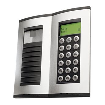
HAC/200 GB INSTALLATION BPT S.p.A. INSTRUCTIONS codes. With a storage capacity of approx. 2,000 secret codes, the unit can be CODED-CALL ENTRY used for entrance control func- PANEL HAC/200 tions. Entry panel with coded call and There is no definite number of user... - Page 5 - Programming menu in Italian and English (select the desired option). Italiano Lingua/Language English - Messages, names, codes and parameters entered via the entry Call code Custom code panel’s keypad. Users management User name 0-80161 (0-13121) _ _ _ _ _ _ _ _ _ _ _ - Option of copying and transfer- _ _ _ _ _ _ _ _ _ _ _ ring the name directory.
- Page 6 12345 can be reset by entering an Users management ric keys and can contain up to 80 sage stored for this function (no emergency code furnished by BPT. Add (adds a new user). letters and numbers in small cha- default setting).
-
Page 7: Hac/200
You can use all codes in the range Copy memory between 2 keys 0 to 80 (for the block code) and in HAC/200 units the range 0 to 161 (for the user Busy system texts 1) Set the entry panel HAC/200 to Add (adds a new system busy code). -
Page 8: Vls/101
DIN rail (EN 50022). Dimensions are shown in figure 2 It can also be surface mounted, using the DIN rail supplied, but fit- ted with terminal covers. Dimensions are shown in figure 2 BPT S.p.A. 30020 Cinto Caomaggiore Venezia - Italy 06.2002/2402-1022... -
Page 9: Vls/100C
VLS/100C INSTALLATION INSTRUCTIONS energized. VLS/100C. RELAY UNIT Function of each terminal VLS/100C is a relay designed to Terminal block A control auxiliary services. When normally open contact common jumper SW2, figure 2, is placed to position C the relay is controlled normally closed contact by the coded signal sent either by Terminal block B... -
Page 10: Si/200
Terminal block G (services) call 1 input call 2 input engaged signal output (for resi- dential systems) general reset enable output BPT S.p.A. 30020 Cinto Caomaggiore Terminal block H (services) Venezia - Italy call 1 output call 2 output 12.2000/2403-1644... -
Page 11: Vsb/200C
43,5 64,5 VSB/200C INSTALLATION INSTRUCTIONS VSB/200C BLOCK SELECTOR 3 - Wait for the programming to be Function of each terminal, figure 1 DISPOSAL The VSB/200C block selector, acknowledged (only if the VPD/100 Do not litter the environment with combined with the SI/200 or Terminal block B or VPDM/100 switchboard is being ground... -
Page 12: Tt/2
The timer is a fully programmable 7 day time clock and is primarily intended to provide inhibit and enable periods for Tradesman push button on all BPT Video and Audio Entry Systems. The delay ‘on’ to lock release, provided by clean changeover contact from the TT/2, can be varied from 2 to 5 seconds. - Page 13 PROGRAMMING THE TIME CLOCK • Only program the ON/OFF time slots you require. DO NOT program 0’s or any other digits into ON/OFF positions unused. e.g. if you require 06:30 ON - 08:30 OFF MON to SUN, use only the first ON/OFF time slot. •...
-
Page 14: Tt/2
BPT UK TRADESMAN TIMER – TT/2 PROGRAMMING POSSIBLE 6 ON – 6 OFF TIMES OVER 7 DAYS Hold down both the PROGRAM and CHANGE buttons until the display blanks, then release. Display will eventually show as indicated on drawing. CHANGE... -
Page 15: A/200N
43,5 • • • • 64,5 • ER/12 A/200N 43,5 INSTALLATION INSTRUCTIONS 64,5 A/200R POWER SUPPLIER The unit is equipped with a transformer capable of powering the HPC/1 entry panel and max. 20 HPP/6 panels (or MVA/100.01 audio module and max. 20 MC call button modules or 10 push-but- tons lights, equal to 20 call push-but- tons, on AZ entry panels). -
Page 16: A/200N
Installation instructions 8A call common 2 output Untighten the fixing screw and remove 11 audio from entry panel the front cover from the back housing, 12 audio to entry panel figure 5. Fix the back housing to the output 14 V AC wall, figure 6A, or to an embedding box, figure 6B, 6C. -
Page 17: Vas/100.30
Via Roma, 41 provided. 30020 Cinto Caomaggiore/VE/Italy Dimensions are shown in figure 2B. http: www.bpt.it/e-mail: info@bpt.it 08.2007/24839200 NOTE. The unit is protected against overloads and short-cicuits by a self- resetting thermal switch, inserted on the primary of the power supply tran- sformer. -
Page 18: Cd/200
XC/200 CD/200 C/200 XC/200 CD/200 XV/200 CD/200 calls from the porter’s switchboard Function of each terminal and wire (fig. 1) (the connection must be made to terminal N2 before note type b can Terminal block +10÷18 VDC be obtained). coded call from entry panel The type of note can be inverted N2 enabling of second call note by sending the code 80160 (block... -
Page 19: Cd/204
CD/204 coded call from entry panel 12 coded call to porter’s switch- board N2 enabling of second call note Terminal block C-IN P call to porter’s switchboard from receiver 1 7A call to receiver 1 P call to porter’s switchboard from receiver 2 7A call to receiver 2 P call to porter’s switchboard... -
Page 20: Yc/200 - Yc/200A
YC/200 YC/200A pulsante servizi ausiliari: max. 24 V, 1 A. - Maximum switching power of auxi- liary services button: max. 24 V, 1 A. Can accommodate 2 modules (YP3 and YPL). HANDSET YC/201 Handset with secrecy of speech. Features similar to receiver YC/200A. Unit YP3 can be used to add 3 auxi- liary buttons to the handset. -
Page 21: Nc/220 - Nc/221
NC/220 NC/221 1)Modulo viva-voce/Hands-free mo- 4)Adattatore per placca AVE/Adapter dule/Modul mit Freisprechfunktion/ for AVE plate/Adapter für Tableau Module vive-voix/Módulo manos AVE/Adaptateur pour platine AVE/ libres/Módulo viva-voz. Adaptador para placa AVE/Adap- 2)Telaio/Chassis/Rahmen/Ch ssis/ tador para placa AVE. Bastidor/Estrutura. copriforo/Hole plug 5)Adattatore 3)Adattatore per placca VIMAR/ adapter/Adapter Abdeckklappe/... - Page 22 AVE system 45 front plate). 3 (fig. 7) A (embedding box). B (BPT hole plug adapter without connecting rods). C (GEWISS Playbus series front plate). NOTE. If you need to remove the module from the chassis, do so with the aid of a screwdriver as illu- strated in fig.
- Page 23 AS/200 BC/200 GB INSTALLATION INSTRUCTIONS using the DIN rail supplied, but fit- DC POWER SUPPLIER ted with terminal covers. VAS/100.20 Dimensions are shown in figure It consist of a card onto which there are the rectifier and the stabilizer. It is capable of supplying 1.7A at 17.5V NOTE.
-
Page 24: Vsi/200
VSI/200 BPT S.p.A. GB INSTALLATION 30020 Cinto Caomaggiore INSTRUCTIONS Venezia - Italy VSI/200 ENTRANCE SELECTOR ) coaxial cable connection; twisted This unit permits the selection of pair connection to terminal blocks two entry panels and is configured B-E-F: to create the following systems: positive video signal •... -
Page 25: Va/200
elapsed, or on completion of the Terminal block D electrical door lock function. (twisted pair connection) positive video signal 3 - Call note. The unit is equipped with two diffe- negative video signal rential call tone generators. call no. 1 The first generator (terminal 8) is activated each time a call is made at Technical features...
Need help?
Do you have a question about the System 200 Audio O&M and is the answer not in the manual?
Questions and answers