Table of Contents
Advertisement
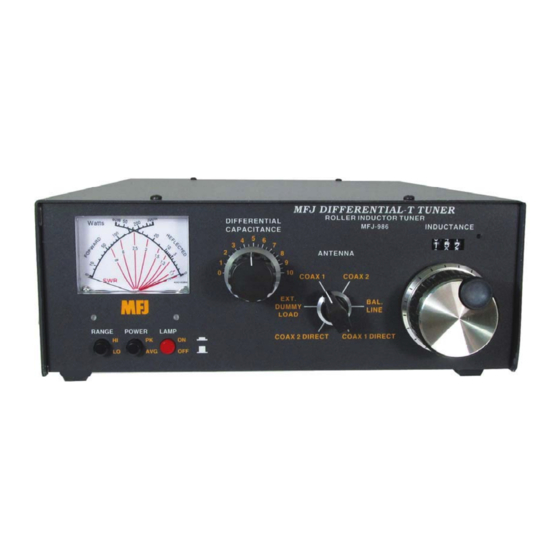
Model MFJ-986
Requires 9VDC Battery or 12VDC Source for Meter Operation
INSTRUCTION MANUAL
CAUTION: Read All Instructions Before Operating Equipment
MFJ ENTERPRISES, INC.
300 Industrial Park Road
Starkville, MS 39759 USA
Tel: 662-323-5869 Fax: 662-323-6551
COPYRIGHT
C
2013 MFJ ENTERPRISES, INC.
VERSION 7A
Advertisement
Table of Contents

Related Manuals for MFJ Differential-T Tuner MFJ-986


Summary of Contents for MFJ Differential-T Tuner MFJ-986
- Page 1 Requires 9VDC Battery or 12VDC Source for Meter Operation INSTRUCTION MANUAL CAUTION: Read All Instructions Before Operating Equipment MFJ ENTERPRISES, INC. 300 Industrial Park Road Starkville, MS 39759 USA Tel: 662-323-5869 Fax: 662-323-6551 COPYRIGHT 2013 MFJ ENTERPRISES, INC. VERSION 7A...
- Page 2 Customers using this manual should report errors or omissions, recommendations for improvements, or other comments to MFJ Enterprises, 300 Industrial Park Road, Starkville, MS 39759. Phone: (662) 323- 5869; FAX: (662) 323-6551. Business hours: M-F 8-4:30 CST.
- Page 3 Tuner Introduction The MFJ-986 roller inductor tuner is a 3000 watt PEP input, 1500 watt PEP output antenna tuner. These power ratings are for load impedances of 35-500 ohms. The MFJ-986 is designed to match 50 ohm output amplifiers, transmitters or transceivers to virtually any antenna. Peak and average forward power, reflected power, and SWR are displayed on the MFJ-986's illuminated cross-needle meter.
- Page 4 2.) 12-VDC External Power: The Meter Lamp power jack is located above the Transmitter connector on the rear panel. Apply power from any filtered dc wall adapter (MFJ-1312D or equivalent), or use your station's 13.8-Vdc supply. A cord fitted with a 2.1-mm plug is supplied with the tuner for this purpose.
- Page 5 The wattmeter has an internal lamp that backlights the meter scale. The lamp circuit requires power from an external 12 Vdc source, such as the optional MFJ-1312B power supply. The rear panel jack accepts a 2.1 mm coaxial plug with the center conductor positive (+) and the sleeve negative (-). The negative lead is grounded inside the tuner.
- Page 6 Instruction Manual Current Balun The MFJ-986 uses a CURRENT balun to force equal currents into the two antenna halves so you get minimum balanced currents. Minimum unbalanced current reduces field pattern distortion which concentrates your power for a stronger signal.
- Page 7 MFJ-986Differential-TTuner Instruction Manual Tune the exciter into a dummy load (most solid state transmitters are "pre-tuned" to 50 ohms and do not require loading with the dummy load). Select the desired antenna with the ANTENNA SELECTOR. Position the capacitor control at the following settings:...
- Page 8 Then, with a small screw driver or pencil, push the reset button through the hole to the right of the counter. This resets the counter to "000". The following table can be used as a guide to tune your MFJ-986 to a specific operating band. When the MFJ-986 is properly tuned, the counter reading should approximately match the number on the table.
- Page 9 MFJ-986Differential-TTuner Instruction Manual WARNING: 1. Never operate the tuner with the top removed. Contact with the components inside the tuner while transmitting will result in painful RF burns. 2. Never rotate the ANTENNA SELECTOR switch while transmitting. Doing so may permanently damage the switch.
- Page 10 CAUTION: For operator safety, a good outside earth ground or water pipe ground should always be installed and connected to the case of the MFJ-986. Make certain the safety ground also connects to the transmitter and other station accessories. A wing nut post marked GROUND is provided for ground connection(s).
- Page 11 (in parallel) as a longwire. The antenna will act like a "T" antenna worked against the station ground. SWR Meter Calibration The MFJ-986 has been calibrated at the factory. If it should ever need to be recalibrated, then follow this procedure: Equipment Needed 1.
- Page 12 1. Refer to Figure 1 for the Test Setup and refer to the PCB layout in Figure 2 for trim pot location. 2. Remove the top of the MFJ-986. 3. Connect the Test Setup equipment as shown in Figure 1. Use a 50-ohm dummy load for the antenna.
- Page 13 You can also send questions by mail to MFJ Enterprises, INC., 300 Industrial Park Road, Starkville, MS 39759; by FAX to 601-323-6551; through Compuserve at 76206,1763; or by email to 76206.1763@Compuserve.com.
- Page 14 MFJ-986Differential-TTuner Instruction Manual Tuning Chart Use the chart below to log values for your station. You may want to copy this chart and post it by your tuner. Frequency (MHz) Capacitor Inductor (counter indicator) 3.75 3.75 3.75 7.15 7.15 10.1 10.1...
- Page 15 MFJ Enterprises, Inc. warrants to the original owner of this product, if manufactured by MFJ Enterprises, Inc. and purchased from an authorized dealer or directly from MFJ Enterprises, Inc. to be free from defects in material and workmanship for a period of 12 months from date of purchase provided the following terms of this warranty are satisfied.
- Page 16 MFJ-986 Manual 300 Industrial Park Road Version 7A Starkville, MS 39759 Printed In U.S.A.
Need help?
Do you have a question about the Differential-T Tuner MFJ-986 and is the answer not in the manual?
Questions and answers