Advertisement
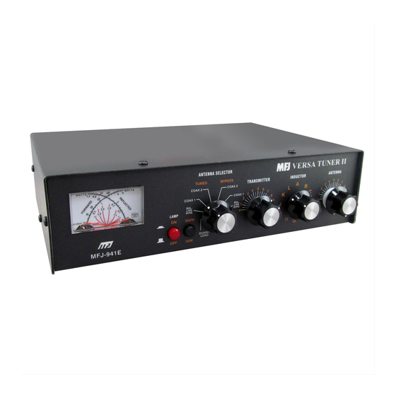
MFJ-941E Versa Tuner II
GENERAL INFORMATION:
The MFJ-941E is designed to match virtually any transmitter to any antenna, including dipoles, inverted-vees, verticals,
mobile whips, beams, random wires, and others fed by coax lines, balanced lines or a single wire. An eight-position
antenna-selector switch provides versatile antenna selection. The MFJ-941E will handle up to 300 Watts of transmitter
RF output power. The MFJ-941E employs a cross-needle meter so forward power, reflected power and SWR may be
read simultaneously.
CROSS-NEEDLE SWR/WATTMETER:
The meter on the MFJ-941E may be used alone or with the tuner. Set the ANTENNA SELECTOR to COAX 1 DIRECT
or COAX 2 DIRECT to use the meter without the tuner. The MFJ-941E utilizes a cross-needle meter so FORWARD
power, REFLECTED power and SWR may be read simultaneously in two ranges. FORWARD power may be read by
setting the power range switch to HI (300 Watts) or LO (30 Watts). Next read the power level on the FORWARD
SCALE. REFLECTED power is shown simultaneously on the REFLECTED SCALE. SWR is determined by observing
the intersection point of the two needles. No SWR sensitivity adjustment is needed to read SWR. The HI range is 300
Watts FORWARD and 60 Watts REFLECTED. The LO range is 30 Watts FORWARD and 6 Watts REFLECTED. The
difference between the HI and LO scales readings is a factor of 10.
The meter lamp can be powered by a 12 Vdc source, such as the optional MFJ-1312B power supply. Use a 2.1mm
coaxial plug with the center conductor of the plug connected to the positive and the sleeve connected to ground. The
METER LAMP ON/OFF switch will activate the meter lamp.
ANTENNA SELECTOR:
The ANTENNA SELECTOR switch utilizes eight positions. They are DUMMY LOAD, BALANCE LINE, COAX 1, and
COAX 2 positions for both BYPASS (direct) and TUNED (through) the tuner operation. An external 50 Ohm dummy
load can be connected to the EXT LOAD connector located at the rear of the tuner. Do not continuously key into the
dummy load for more than 2 minutes at a time.
CAUTION:
Never use the MFJ-941E for OVER 300 Watts of RF output power, even in the
DIRECT or DUMMY LOAD positions.
1
MFJ VERSA TUNER II
Advertisement
Table of Contents

Related Manuals for MFJ MFJ-941E


Summary of Contents for MFJ MFJ-941E
- Page 1 CROSS-NEEDLE SWR/WATTMETER: The meter on the MFJ-941E may be used alone or with the tuner. Set the ANTENNA SELECTOR to COAX 1 DIRECT or COAX 2 DIRECT to use the meter without the tuner. The MFJ-941E utilizes a cross-needle meter so FORWARD power, REFLECTED power and SWR may be read simultaneously in two ranges.
-
Page 2: Installation
BALANCED LINE. A jumper wire from the WIRE binding post, as indicated by a dotted line on the MFJ-941E, should be connected to one of the posts of the BALANCE LINE. This couples the MFJ-941E to the balanced line through a 4:1 balun. -
Page 3: Front Panel Overview
TRANSMITTER and ANTENNA controls represent maximum capacitance at position 10. For optimum operation of the MFJ-941E, the transmitter must be tuned to a 50 Ohm output impedance at the frequency of operation. The ANTENNA SELECTOR switch should be set to DUMMY LOAD for tuning up the transmitter. - Page 4 MFJ-941E Versa Tuner II While transmitting a steady state carrier (CW) alternately adjust TRANSMITTER and ANTENNA controls for minimum SWR. Since both controls interact, the two controls can best be adjusted by turning the TRANSMITTER control one small increment at a time, then rotating the ANTENNA control for minimum SWR.
-
Page 5: In Case Of Difficulty
1:1 SWR is not achievable. In such cases, the length of the antenna may be increased or decreased to improve SWR. SWR of 1:1 may occur at more than one set of control settings on the MFJ-941E. When an SWR of 1:1 is obtained, make sure that the transmitter power is relatively high. If transmitter power has decreased substantially, try another INDUCTOR control setting and repeat Step 3. - Page 6 MFJ-941E Versa Tuner II This problem often occurs on 80 meters if an odd quarter-wave (60 to 70 foot) open wire line is used to feed a half-wave (100 to 140 foot) dipole. The odd quarter-wave line transforms the dipole's low impedance to over three thousand Ohms at the tuner.
- Page 7 If you have any problem with this unit first check the appropriate section of this manual. If the manual does not reference your problem or your problem is not solved by reading the manual, you may call MFJ Technical Service at 601-323-0549 or the MFJ Factory at 601-323-5869.
- Page 8 MFJ-941E Versa Tuner II You can also send questions by mail to MFJ Enterprises, INC., P.O. Box 494, Mississippi State, MS 39762; by FAX to 601-323-6551; through Compuserve at 76206,1763; or by email to 76206.1763@Compuserve.com. Send a complete description of your problem, an explanation of exactly how you are using your unit, and a complete description of your...
- Page 9 MFJ-941E Versa Tuner II Schematic:...
Need help?
Do you have a question about the MFJ-941E and is the answer not in the manual?
Questions and answers