Table of Contents
Advertisement
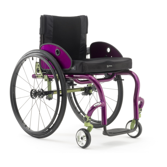
Thank you for purchasing a Rogue wheelchair!
Please do not use this wheelchair without first reading this entire manual.
BEFORE riding, you should be trained in the safe use of this chair by an
Assistive Technology Practitioner (ATP) or clinical professional.
If you have any questions or concerns about any aspect of this wheelchair,
this manual, or the service provided by us or your retail supplier, please do
not hesitate to contact us by telephone at:
715‐254‐0991
In writing at:
Ki Mobility
4848 Industrial Park Road
Stevens Point, Wisconsin 54481
USA
Or via email at:
sales@kimobility.com
1
2
Advertisement
Table of Contents

Related Manuals for Ki Mobility Rogue


Summary of Contents for Ki Mobility Rogue
- Page 1 Thank you for purchasing a Rogue wheelchair! Please do not use this wheelchair without first reading this entire manual. BEFORE riding, you should be trained in the safe use of this chair by an Assistive Technology Practitioner (ATP) or clinical professional. If you have any questions or concerns about any aspect of this wheelchair, this manual, or the service provided by us or your retail supplier, please do not hesitate to contact us by telephone at: 715‐254‐0991 In writing at: Ki Mobility 4848 Industrial Park Road Stevens Point, Wisconsin 54481 USA Or via email at: sales@kimobility.com 1 2 ...
-
Page 2: Table Of Contents
J. Modifying Your Wheelchair ............ 1 0 and size and position of the front casters. Any change to any of these K. Wheelchair Stability .............. 1 0 items will change the stability of your wheelchair. You should only make changes after consulting with a qualified professional. V. SET UP AND USE OF YOUR WHEELCHAIR ........ 12 A. Your Rogue & Its Parts ............. 1 2 IV. WARNINGS B. Transit Use ................ 1 3 C. Height Adjustable T‐Arms ............ 1 6 A. Signal Words D. Padded Swing‐Away Adjustable Armrests ........ 1 7 E. Armrest Warnings .............. 1 7 ... -
Page 3: General Warnings
IV. WARNINGS IV. WARNINGS B. General Warnings C. Positioning Belts Positioning belts are designed to assist with proper positioning within the wheelchair. They are not designed as seat belts. Use positioning belts ONLY WARNING: Do not exceed the weight limit of 275 pounds (350 pounds for to help support the user’s posture. Misuse of positioning belts may cause se‐ heavy duty option) for the Rogue. This is the combined weight of user and all vere injury to or death of the user. items carried. Exceeding the weight limit can cause damage to your chair or Ensure the user does not slide underneath the positioning belt in the increase the likelihood of a fall or tip back resulting in severe injury or death to wheelchair seat. If this occurs, the user’s breathing may be hampered the user or others. causing death or serious injury. The positioning belt should have a snug fit; tight enough to hold their posi‐ DANGER: Do not use this chair for weight training. The movement of the tion, but not so tight as to restrict breathing. You should be able to slide additional weight will alter the center of gravity of the wheelchair increasing the your hand between the positioning belt and the user. likelihood of a tip‐over which can cause damage to your chair or cause severe injury or death to the user or others. NEVER Use Positioning Belts: a) As a restraint. A restraint requires a doctor’s order. WARNING: If your wheelchair is equipped with inflatable tires, make sure b) On a user who is unconscious. the tires have been inflated to the correct tire pressure as indicated on the c) As a occupant restraint in a motor vehicle. A positioning belt is not de‐ side wall of the tire. Your wheelchair provider can determine if you have signed to replace a seat belt that is attached to the frame of a vehicle, inflatable tires. Using your wheelchair without properly inflated tires can have which would be required of an effective seat belt. During a sudden stop, an effect on the stability of the wheelchair causing it to tip over resulting in ... -
Page 4: Riding Your Wheelchair
IV. WARNINGS IV. WARNINGS D. Riding Your Wheelchair E. Power Drives Your chair is designed for use on solid, flat surfaces such as concrete, asphalt Ki Mobility does not recommend the installation of power drive systems on and flooring. Use caution if you push your wheelchair on a wet or slick surface. any Rogue wheelchair. Rogue wheelchairs have not been designed or tested as power wheelchairs. If you add a power drive system to a Rogue wheelchair, be sure the manufactur‐ WARNING: Do not push your chair in sand, loose soil or over rough terrain. er of the power drive system has validated and approved the combination of This may cause a loss of stability and result in a fall or loss of control and the power drive system and Rogue wheelchair as safe and effective. cause serious injury or death. WARNING: Use of a power drive system that has not been properly validated DANGER: In most states, wheelchairs are not legal for use on public roads. If could result in serious injury or death. you find you must push on a public road, be alert to the danger of motor vehicles. Use of a wheelchair on a public road can cause serious injury or death. F. Ascending Stairs Have at least two people, who have sufficient strength and skill to handle the weight of the user and wheelchair, assist when trying to go up a set of WARNING: Obstacles and road hazards (such as potholes and broken stairs in this wheelchair. pavement) can damage your chair and may cause a fall, tip‐over or loss of control. Failure to comply with this instruction could result in serious injury or Move the wheelchair and user backwards up the stairs. death. Position one person behind the user and one person in front of the user. The person in front must hold on to a non‐removable part of the wheelchair. The rear attendant tilts the chair back and they both lift together. Take one DANGER: Do not ride your wheelchair on an escalator. Use of a wheelchair on step at a time. an escalator can cause serious injury or death. ... -
Page 5: Transfers
IV. WARNINGS IV. WARNINGS H. Transfers J. Modifying your Wheelchair A transfer requires good balance and stability. You should receive training Your wheelchair was engineered and manufactured under strict design from your therapist before attempting to do a transfer on your own. controls. An integral part of this process is ensuring the various components work together correctly; they have been tested to various standards to ensure Before transferring out of your wheelchair every caution should be taken to quality and are approved to work together. reduce the gap between the two surfaces. NO ONE SHOULD MODIFY THIS WHEELCHAIR EXCEPT BY ASSEMBLING Engage the wheel locks to lock the rear wheels. APPROVED OPTIONS. THERE ARE NO APPROVED OPTIONS THAT Rotate the casters forward to increase the wheelbase of the wheelchair. INVOLVE DRILLING OR CUTTING THE FRAME BY ANYONE OTHER THAN A TRAINED KI MOBILITY ASSOCIATE. Contact Ki Mobility or an authorized Remove or swing away the footrests Ki Mobility supplier before adding any accessories or components not Have someone assist you unless you are well experienced in transfers. provided by Ki Mobility It is dangerous to transfer on your own. It requires good balance and agility. Be aware there is a point during every transfer when the wheelchair seat is not below you. DANGER: Failure to comply to these instructions may cause the wheelchair to fail and result in serious injury or death. K. Wheelchair Stability WARNING: Failure to perform a transfer properly can result in a fall and can cause severe injury or death. To ensure proper stability, of your wheelchair you must make sure the center of gravity and the wheelchairs base of support is correct for your balance and I. Your Wheelchair and the Environment abilities. Many factors can affect these two elements; Your wheelchair is made of many different materials including metal and ... -
Page 6: Set Up And Use Of Your Wheelchair
IV. WARNINGS V. SET UP & USE OF YOUR WHEELCHAIR K. Wheelchair Stability A. Your Rogue & Its Parts a) Inspect and maintain this chair strictly per Maintenance Chart in Section VI. b) If you detect a problem, make sure to service or repair the chair before use. WARNING: Changes to your Center of Gravity during your daily activities may c) Have a complete inspection, safety check and service of your chair occur many times a day and change and affect the stability of your wheelchair. performed by an authorized supplier annually. You should be aware of these activities and take precautions to minimize the risk of a fall. Failure to comply with the instruction above could result in serious injury or death. WARNING: Failure to read or comply with these instructions may result in damage to your wheelchair, a fall or loss of control causing severe injury to the user or others. WARNING: Dressing in your wheelchair produces movements and momentary positions that can reduce stability. Insure that your anti‐tips are in place and rotate your casters forward. Failure to comply with the instruction above could result in serious injury or death. WARNING: Be very careful when reaching for objects if this movement requires you to shift in your seat. This changes your center of gravity. Insure that your anti‐tips are in place. Failure to comply with the instruction above could result in serious injury or death. WARNING: Pushing up an incline shifts your center of gravity rearward and can reduce stability. Ensure your anti tips are in place. Failure to comply with the instruction above could result in serious injury or death. WARNING: If attempting a wheelie to get over a curb or obstacle, ensure your anti ‐tips are in place and lean forward. Do not attempt a wheelie unless you have been trained and always have an attendant behind you to provide assistance if needed. Failure to comply with the instruction above could result in serious injury or death. WARNING: Placing items on the back or front of your wheelchair, such as a backpack or briefcase, alters the balance and center of gravity of the wheelchair. Since the weight of these items can vary greatly at each use do ... -
Page 7: Transit Use
V. SET UP & USE OF YOUR WHEELCHAIR V. SET UP & USE OF YOUR WHEELCHAIR B. Transit Use (Continued) B. Transit Use Fig. 1 Attach wheelchair tie‐downs to the four It is always safest to transfer out of your wheelchair onto a seat in a motor securement points (two front, two rear) on vehicle with appropriate seat and shoulder belts. Never use this wheelchair as a the Rogue wheelchair with the Transit seat in a motor vehicle unless it has been equipped with the Transit Option. Option (Fig. 1) in accordance with the The Rogue Series wheelchair equipped with the Transit Option has been tested wheelchair tie‐down manufacturer’s to and passed the RESNA WC‐4:2012, Section 19: Wheelchairs used as instructions and RESNA WC‐4:2012, seats in motor vehicles and ISO 7176‐19:2008 Wheelchairs ‐‐ Part 19: Section 18 or ISO 10542‐1:2012 ‐ Part 1. Wheeled mobility devices for use as seats in motor vehicles. RESNA and Attach occupant restraints in accordance ISO standards are designed to test the structural integrity of the wheelchair as with the occupant restraint manufacturer’s a seat for use in a motor vehicle. These standards are also designed to create instructions and RESNA WC‐4:2012, compatibility with Wheelchair Tie‐down and Occupant Restraint Systems Section 18 or ISO 10542‐1:2012, Part 1. (WTORS). Use of lap belts, chest straps, shoulder harnesses, any other positioning strap Not all configurations of the Rogue Series wheelchairs are compatible with the system or positioning accessory should not be used, or relied on as an occupant Transit Option. Ki Mobility manages the configuration and does not offer the restraint, unless it is marked as such by the manufacturer in accordance with Rogue Series wheelchair except in compatible configurations. If you make RESNA WC‐4:2012, Section 18 or ISO 10542‐1:2012, Part 1. changes to your Rogue Series wheelchair after your receive it, you should contact your wheelchair provider or Ki Mobility to make sure it is appropriate to continue to ... -
Page 8: Height Adjustable T-Arms
V. SET UP & USE OF YOUR WHEELCHAIR V. SET UP & USE OF YOUR WHEELCHAIR B. Transit Use (Continued) C. Height Adjustable T‐Arms (Fig. 2) 1. Installation a) Slide the outer armpost into the receiver mounted to the wheelchair frame. DANGER: Failure to comply with transit use instructions, on pages 13 and 14, b) The armrest will automatically lock into place. Check to make sure the could result in severe injury or death! locking lever is as shown (Fig. 2 B) NOTE: To obtain a copy of RESNA or ISO standards please contact the stand‐ 2. Height Adjustment ards organizations below: a) Rotate release lever (Fig. 2 A) b) Slide armrest pad up or down to desired height. RESNA 1700 North Moore St., Suite 1540 c) Return lever to locked position against arm post. Arlington, VA 22209 d) Push arm pad until upper arm post locks firmly into place. Check to make Phone: 703‐524‐6686 sure the locking lever is as shown (Fig. 2 A) Fax: 703‐524‐6630 3. Removing Armrest Email: technicalstandards@resna.org a) Squeeze release lever (Fig. 2 B) and remove the armrest. 4. Replacing Armrest ANSI/RESNA Standards: a) Slide armrest back into receiver. ... -
Page 9: Padded Swing-Away Adjustable Armrests
V. SET UP & USE OF YOUR WHEELCHAIR V. SET UP & USE OF YOUR WHEELCHAIR D. Padded Swing‐Away Adjustable Armrests (Fig. 3) F. Center of Gravity Adjustment (Fig. 4) 1. Installation The most important adjustment on your Rogue wheelchair is the position of the Fig. 3 rear axle. a) Slide armrest into receiver tube on rear of frame. Ensuring the You can adjust your center of gravity by moving the two camber mount clamps pin engages the receiver. (A) forward or rearward on the seat tube (B). 2. Swinging Away Moving the camber mount clamps forward shortens the wheelbase and lightens the front end, making your chair more maneuverable. Moving the camber a) Lift armrest up until pin mounts rearward makes the chair more stable and less likely to tip over disengages from receiver and rearward. rotate to the side. NOTE– Changes to the center of gravity may affect the rear seat height 3. Removing Armrest (Section J), toe‐in/toe‐out of the rear wheels (Section I.) and the squareness a) Pull armrest straight out of of the casters (Section L). If you change your center of gravity position, re‐ receiver. adjust all of these settings if necessary. 4. Adjusting Receiver Angle NOTE– Adjusting your chair’s center of gravity will require re‐adjusting the location of the wheel locks (if provided). See Section S for instructions on a) Remove two M6 bolts from receiver. adjusting the wheel locks. b) Receiver is now free to rotate in 3˚ increments. Adjust arm to desired angle. c) Slide bolts through locating holes and tighten nuts. ... -
Page 10: Wheel Camber
V. SET UP & USE OF YOUR WHEELCHAIR V. SET UP & USE OF YOUR WHEELCHAIR G. Wheel Camber (Fig. 6‐8) F. Center of Gravity Adjustment (Continued) Wheel camber, shown as angular relationship (7‐A), provides greater side‐to‐ To adjust the center of gravity location (Fig. 5): side stability due to the increased width and angle of the wheelbase. It also a) Remove both rear wheels. allows for quicker turning and greater access to the top of the handrims. b) Loosen the 2 screws (C) and nuts that secure the camber mounts (A Wheel camber is determined by pairs of interchangeable camber adapters (B) and B) to the seat tubes. which are available from your authorized supplier in 0°, 2°, 4°, 6° and 8° angles. c) Slide the camber mounts forward or rearward along the seat tube to the desired hole location. d) Repeat on the other side. B e) Make sure the mounts on both sides of the frame are adjusted equally on both sides of the frame before tightening all the screws and nuts. A f) Once the camber mount clamps are secured, attach the rear wheels, occupy the chair and maneuver it with a spotter to get a feel for the new adjustment. X˚ Fig. 8 Fig. 6 Fig. B A H. Wheelbase Width Adjustment Adjusting the wheelbase width allows the rider the option to move the wheels ... -
Page 11: Setting Toe To Zero
V. SET UP & USE OF YOUR WHEELCHAIR V. SET UP & USE OF YOUR WHEELCHAIR I. Setting Toe to Zero (Fig. 10) J. Rear Seat Height Adjustment (Fig. 11) Rear seat height can be adjusted by repositioning the Tubular Component NOTE– A wheelchair equipped with 0° camber plugs cannot have a toe‐in toe‐ System (TCS). out condition. This adjustment is only required when using 2°, 4°, 6° and 8° camber adapters. Fig.11 1. Remove your wheels by depressing the buttons on the quick release axle. Toe refers to how well the rear wheels of the chair are aligned relative to the ground. It affects how well the chair will roll. Drag or rolling resistance is opti‐ 2. U se a 4mm Allen wrench and 8mm mally minimized when the wheel toe is set to zero. open end wrench to remove the two bolts (A) holding the upper and lower To set Toe to zero: mounting brackets together. (See Fig. 1. Loosen the cap screws (A) (1 per side) that secure the camber tube 11) Reposition the mounting brackets clamp. to the desired height and replace the two M5 bolts. 2. Rotate the camber tube (B) until the screws (C) that secure the camber spuds are level with the ground. The toe is now set at zero. 3. R epeat on both sides of the wheelchair. A 3. Before tightening the screws (A), make certain that the camber tube is centered left‐to‐right relative to the wheelchair frame. There should be an equal gap on both sides or none at all. ... -
Page 12: Caster Angle Adjustment
2. Loosen the M8 button head cap screw (A) on the bottom of the caster d) Release the button to lock axle in sleeve. housing wing. (Fig. 13) Then turn the screw on the top of the caster hous‐ If release button does not fully extend and ing wing. (B). Loosening will begin to tilt the caster forward. By tightening the locking balls do not move in to the you will turn rearward. locked position after releasing the button, 3. Turn until you have aligned the caster stem so it is perpendicular to the the axle length needs to be adjusted. floor. 2. Adjusting Axles (Fig. 16) 4. Place a large right triangle against the flat surface of the fork as shown. a) To adjust the axle you will need a 19mm (Fig. 14) wrench to turn the adjustment nut. You will also need a 11mm wrench to 5. With the rack and pinion system of the Rogue the casters should always be securely hold the ball detent end of the axle to prevent it from turning. able to be square. b) If the wheel and axle will not lock into the camber plug then the axle requires adjustment. Turn the nut counter‐clockwise approximately 1/4 Fig. 13 Fig. 14 revolution and try to lock the axle into the camber plug. If it doesn't lock, continue making small nut adjustments until it securely locks. c) If the wheel is locked on the chair but there is excessive wheel play (the B wheel hub can be pushed back and forth on the axle) then adjust the nut clockwise until there is no perceptible gap between the wheel and camber tube and the axle is securely locked onto the chair. Review and understand Section M. Wheel Installation & Removal before attempting an axle adjustment! ... -
Page 13: Adjusting The Footrest
V. SET UP & USE OF YOUR WHEELCHAIR V. SET UP & USE OF YOUR WHEELCHAIR N. Adjusting the Footrest (Fig. 17) P. Anti‐Tips (Fig. 19‐21) Height Adjustment of your footrest: Anti‐tip tubes help prevent your wheelchair from tipping over backwards. When Fig. 17 adjusted properly they provide a significant increase in rearward stability. Your 1. Locate the set screw on each stability can be affected by traversing uneven ground, a ramp, slope or other side of the frame (A). surface that changes your relationship to gravity. Your stability can also be affected by other forces acting on you and your wheelchair such as someone 2. Loosen the set screw on each pushing down or leaning on your push handles or other parts of your chair. side of the frame using an M3 This can happen to even the most experienced wheelchair user. People in your Allen wrench. Do not environment do not necessarily understand they are impacting your stability. remove. Ki Mobility strongly recommends the use of Anti‐Tip tubes! 3. Adjust footrest tube up or down to achieve the desired height (B). Anti‐tips must be used at all times. Whether traversing uneven ground or 4. Ensure both sides are adjusted sitting in a crowded room, the unexpected may occur and your weight can equally. dramatically shift causing a fall which could cause serious injury or death. 5. Retighten each set screw to 1. I nserting Anti‐Tip Tubes Into Receiver 40 in./lbs. ... -
Page 14: Upholstery Fabric
Release pin. backrest frame into the upright position. d) Repeat with second anti‐tip tube. e) Remember to return anti‐tip tubes to down position after completing Fig. 21 maneuver. Q. Upholstery Fabric 1. You must immediately replace seat and back upholstery that has worn through and shows signs of failing. If you fail to do so, the seat or back may fail. Fig. 22 Fig. 23 2. The seat sling material will weaken over time. Look for fraying, thin spots, or stretching of fabrics especially at edges and seams. This should be done 2. Relaxed Position (Fig. 24) weekly. The Rogue backrest will also open into an extended position by pulling the 3. The repeated action of transferring to your wheelchair will weaken sling ma‐ backrest release cable outward and applying pressure against the back while terial and result in the need to inspect and replace the seat more often. remaining in the wheelchair. 4. Be aware that laundering or excess moisture will reduce flame retardation of the fabric. 5. Contact your wheelchair provider if you have concerns about your seat or Fig. 24 back, or feel it needs to be replaced. WARNING: Failure to comply with these instructions may result in damage to your wheelchair, a fall or loss of control causing severe injury to the user or others. 27 28 ... -
Page 15: Wheel Locks
V. SET UP & USE OF YOUR WHEELCHAIR V. SET UP & USE OF YOUR WHEELCHAIR S. Wheel Locks (Fig. 26, 27) R. Backrest (Continued) Rogue wheelchairs are shipped with one of several different types of wheel 3. Backrest Angle Adjustment (Fig. 25) locks pre‐installed. There are a series of 10 holes used for adjusting the angle of your Rogue Push to Lock backrest (C). Each hole will change the angle by 3 degrees (+/‐). Moving Fig. 26 the placement of the screw (A) into a locating hole further towards the front of Pull to Lock the chair will result in opening of the back angle. Choosing a hole location Push to Lock (flush mount) closer to the rear of the chair results in closing of the back angle. Short thro Scissor To adjust the angle of the backrest: The clamp assembly works the same for all 1. Using a 3mm Allen wrench and 8mm socket wrench remove the screw wheel locks. (A) and nut and washer (B) on the backrest plate (Fig. 25) where angle a) Using a 5 mm Allen wrench, turn one of adjustment holes are located (D). the screws in the clamp until it runs easily (less than one turn). 2. Align the backrest tube and saddle (C) with desired hole and reinsert screw (A) through locating holes, plastic saddle and into backrest tube b) Repeat the same process with the (C). (Fig. 25) second of the two screws so the clamp can be adjusted on the frame. ... -
Page 16: Seat Sling
VI. MAINTENANCE V. SET UP & USE OF YOUR WHEELCHAIR A. Inspecting Your Wheelchair T. Seat Sling Regular and routine maintenance will extend the life of your wheelchair while Seat sling includes a folding strap on the seat to assist in folding the chair. improving its performance. Wheelchair repairs and the replacement of parts NOTE– The seat sling folding strap is not intended as a carrying strap. should be done by a qualified technician of an authorized Ki Mobility Supplier. 1. General Inspections a) Clean your chair at least once per month. You may need to clean your chair more frequently if you operate it in dirty environments, such as a work site. b) Check to be sure that all fasteners are tight. Unless otherwise noted, fas‐ U. Cushion Installation teners should be tightened to 40 in./lbs. a) The Tsunami was designed to be used with a proper wheelchair c) Check Tires and Casters: cushion. Check the tire for tread wear. Replace the tires if the tread is worn off or has flat spots or visible cracks. If you have inflatable tires with a valve stem, check the pressure and set DANGER: Sitting for long periods of time without a proper wheelchair cushion to the pressure listed on the tire sidewall. can cause pressure ulcers which can be serious in nature and result in death. DANGER: Replace worn tires. The wheel locks will not grip properly if you b) The standard sling upholstery is provided with loop Velcro type fastener fail to maintain the air pressure shown on tire sidewall. This could result in strips. The cushion being used should have hook Velcro type fasteners that a fall or loss of control and cause severe injury or death. can engage the loop of the seat sling to keep the cushion from sliding out from under you. Make sure the cushion is securely attached before d) ... -
Page 17: Cleaning
VI. MAINTENANCE VI. MAINTENANCE A. Inspecting Your Wheelchair (Continued) B. Cleaning Weekly a) Check wheel locks to be sure they are adjusted correctly. 1. Axles and wheels b) Check axle sleeves to ensure the axle sleeve nuts are tight. a) Clean around the axles and wheels WEEKLY with a damp rag. c) Check for broken, bent or loose spokes. b) Hair and lint will lodge in the caster housing. Disassemble the caster housing every six months to remove entangled hair. d) Check that casters can spin freely. NOTE: Do not use WD‐40 or any other penetrating oil on this wheelchair. This e) Inspect tires and casters for wear spots. will destroy the sealed bearings. f) Check pneumatic tires for proper inflation. NOTE: Do not use any chemical cleaning agents on casters or tires. Monthly a) Inspect rear wheel axles and tighten if necessary. b) Inspect caster housing bearings for hair build up and remove if 2. Upholstery necessary. a) Hand‐wash only (machine washing can cause damage to the fabric). c) Inspect wheel locks to be sure assembly is tight. Make sure b) Line dry only. DO NOT machine dry; heat from the dryer will damage fabric. wheel locks properly engage the tires. d) Check that all fasteners are tight and secure. e) Inspect hand grips to ensure they are not loose. f) ... -
Page 18: Warranty
The expected life of the frame is five years. Limitations to the Warranty 1. We do not warrant: a) Wear items: Upholstery, tires, armrest pads, tubes, armrests and push ‐handle grips. b) Damage resulting from neglect, misuse or from improper installation or repair. c) Damage from exceeding weight limit. 2. This warranty is VOID if the original chair serial number tag is removed or altered. 3. This warranty is VOID if the original chair has been modified from its original condition and it is determined the modification resulted in failure. 4. This warranty applies in the USA only. Check with your supplier to find out if international warranties apply. Ki Mobility’s Responsibility Ki Mobility’s only liability is to replace or repair, at our discretion, the covered parts. There are no other remedies, expressed or implied. Your Responsibility a) Notify Ki Mobility, via an authorized supplier, prior to the end of the warranty period and get a return authorization (RA) for the return or repair of the covered parts. b) Have the supplier send the authorized return, freight pre‐paid, to: Ki Mobility 4848 Industrial Park Road Stevens Point, WI 54481 c) Pay any charges for labor to repair or install parts. Ki Mobility 4848 Industrial Park Road Stevens Point, Wisconsin 54481 715‐254‐0991 www.kimobility.com DCN0026.7 35 36 ...
Need help?
Do you have a question about the Rogue and is the answer not in the manual?
Questions and answers