
Related Manuals for DeWalt DWE7491-XE


Summary of Contents for DeWalt DWE7491-XE
- Page 1 Questions? See us on the World Wide Web at www.dewalt.com INSTRUCTION MANUAL DWE7491-XE HEAVY-DUTY 254 MM (10") JOB SITE TABLE SAW...
- Page 2 4. Keep other persons away. Definitions: Safety Guidelines Do not let persons, especially children, not involved in the work, touch the tool or the extension cord and keep them away from the work area. The definitions below describe the level of severity for each signal word. Please read the manual and pay 5.
- Page 3 21. Always use blades with correct size and shape (diamond versus round) of arbour holes. Blades that do • Do not apply lubricants to the blade when it is running. not match the mounting hardware of the saw will run eccentrically, causing loss of control. •...
-
Page 4: Package Contents
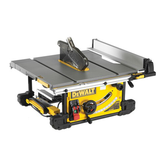
• Take the time to thoroughly read and understand this manual prior to operation. Description (fig. 2, 3) Your DWE7491-XE jobsite table saw has been designed to perform the four main sawing operations of ripping, cross-cutting, bevelling and mitring easily, accurately and safely in wood, wood products and plastics. This unit is designed for use with a 254 mm carbide-tipped blade. - Page 5 MINIMUM GAUGE FOR CORD SETS FIG. 3 For Cable length (m): Use Cable with minimum rating (Amperes) Tool Amperes 0 - 3.4 3.5 - 5.0 5.1 - 7.0 7.1 - 12.0 12.1 - 20.0 – WARNING: We recommend the use of a residual current device with a residual current rating of 30mA or less. WARNING: ALWAYS wear approved protective safety equipment complying with the following standards: •...
- Page 6 TO REMOVE THE BLADE GUARD ASSEMBLY (FIG. 4) 5. In order to prevent the screw heads from marring the surface to which you clamp the saw, attach two strips of scrap wood to the bottom of the plywood base. These strips can be attached with wood screws installed 1.
- Page 7 FIG. 9 Bevel stop and pointer adjustment (Fig. 13) 1. Raise the blade fully by rotating the blade height FIG. 13 adjustment wheel (F) clockwise until it stops. 2. Unlock the bevel lock lever (G) by pushing it up and to the right.
- Page 8 FIG. 17 WARNING: • Always observe the safety instructions and applicable regulations. • Ensure the machine is placed to satisfy ergonomic conditions in terms of table height and stability. The machine site shall be chosen so that the operator has a good overview and enough free surrounding space around the machine that allow handling of the workpiece without any restrictions.
- Page 9 Cross-Cutting and Bevel Crosscutting FIG. 21 FIG. 22 1. Remove the rip fence and install the mitre gauge in the desired slot. 2. Lock the mitre gauge at 0°. 3. Proceed as for ripping. Mitre Cuts (fig. 1) 1. Set the mitre gauge (J) to the required angle. NOTE: Always hold the workpiece tightly against the face of the mitre gauge.
-
Page 10: Service Information
VIC 3076 Australia or call 1800 338 002 or (NZ) 0800 339 258. WARNING: Sharp edges. Unwanted Tools and the Environment Take your tool to an authorized DEWALT repair agent where it will bedisposed of in an environmentally safe way. Service Information Please have the following information available for all service calls:... - Page 12 82 Taryn Drive, Epping, VIC 3076 Australia • 1800 338 002 (Aust) or 0800 339 258 (NZ) www.dewalt.com.au • www.dewalt.co.nz (MAR14) Part No. N393535 DWE7491-XE Copyright © 2013, 2014 D WALT The following are trademarks for one or more D WALT power tools: the yellow and black color scheme;...
Need help?
Do you have a question about the DWE7491-XE and is the answer not in the manual?
Questions and answers