Faraday MPC-6000 Programming Manual
Fire alarm system control unit
Hide thumbs
Also See for MPC-6000:
- Installation, operation and maintenance manual (108 pages) ,
- Programming manual (40 pages) ,
- Installation instructions (2 pages)
Table of Contents
Advertisement
Advertisement
Table of Contents

Related Manuals for Faraday MPC-6000


Summary of Contents for Faraday MPC-6000
- Page 1 MPC-6000 / MPC-7000 / RND-2 Fire Alarm System Control Unit Programming Manual Siemens Building Technologies, Inc. 8 Fernwood Road • Florham Park, NJ 07932 Tel: (973) 593-2600 • Fax: (973) 593-6670 Web: www.faradayfirealarms.com P/N 315-049403FA-6 (3.23.06)
-
Page 3: Table Of Contents
Table Of Contents Introduction..........................1 The Access levels ........................1 User Level ......................1 Maintenance Level....................2 Technician Level.....................2 The Operator Interface ......................3 Interface for User and Maintenance Levels ............3 Interface for the Technician Level................4 Entering Alphanumeric Characters .................5 QUICK START........................6 Automatic programming of a new system...............6 Manual programming of a system ................7 Programming Concepts...................... - Page 4 Printing the Sensitivity Levels ................23 Editing the System Label ..................23 Editing the Device Labels ..................23 Starting Quick Test ....................23 Configuring NAC sound time for Quick Test ............24 Configuring the printer during Quick Test .............24 Programming a Device ..................24 Technician Level ........................25 Activating the Releasing Application Features............25 Configuring the Releasing Application Features ...........25 Editing a Device Configuration ................26...
-
Page 5: Introduction
Although programming requires no special software skills, a thorough working knowledge of Fire Alarm Control Panels and devices is assumed. There are two ways to program an MPC-6000/7000/RND-2 fire alarm system control unit from the front panel keypad: 1. Auto Program. Using Auto Program will quickly configure the FACP in a General Alarm configuration. -
Page 6: Maintenance Level
M P C - 6 0 0 0 M P C - 7 0 0 0 R N D - 2 P R O G R A M M I N G M A N U A L Maintenance Level The Maintenance Level is accessed via the User Menu and the correct password. -
Page 7: The Operator Interface
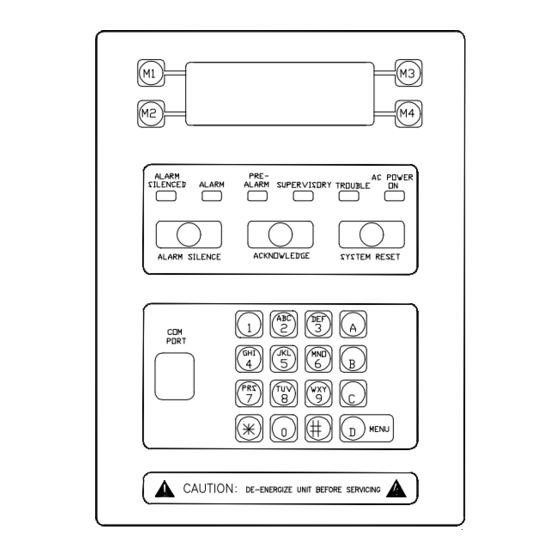
The Operator Interface Interface for User and Maintenance Levels The operator interface for configuring and programming the MPC-6000/7000 uses the 4 line by 20 character LCD display, the M1 through M4 buttons on the left and right of the display and sixteen push buttons at the bottom of the interface. User Level and Maintenance Level utilize the LCD display and the four buttons (two on each side of the display) to navigate and alter the basic operation of the panel. -
Page 8: Interface For The Technician Level
M P C - 6 0 0 0 M P C - 7 0 0 0 R N D - 2 P R O G R A M M I N G M A N U A L Interface for the Technician Level When the Technician Level is accessed using the password, the LCD display and the keypad are used to program the panel, and to view the programming if desired. -
Page 9: Entering Alphanumeric Characters
M P C - 6 0 0 0 M P C - 7 0 0 0 R N D - 2 P R O G R A M M I N G M A N U A L Entering Alphanumeric Characters Entry of alphanumeric data using the keypad is as follows: •... -
Page 10: Quick Start
M P C - 6 0 0 0 M P C - 7 0 0 0 R N D - 2 P R O G R A M M I N G M A N U A L QUICK START Automatic programming of a new system This is the quickest way to get a system operational. -
Page 11: Manual Programming Of A System
M P C - 6 0 0 0 M P C - 7 0 0 0 R N D - 2 P R O G R A M M I N G M A N U A L Step Action Description Note NOTE #1: The backup configuration will now contain a configuration as follows:... - Page 12 IMPORTANT NOTE: Special considerations apply to programming an RND-2 panel as opposed to either an MPC-6000 or MPC-7000 panel. No devices (inputs or outputs), no NACs, no SLUs nor any SRUs can be connected or programmed. Only the MPC-DACT DACT board or the CT-1K City Tie board, the RDC-2 Annunciator and the network may be connected and programmed to an RND-2 panel.
-
Page 13: Programming Concepts
M P C - 6 0 0 0 M P C - 7 0 0 0 R N D - 2 P R O G R A M M I N G M A N U A L Programming Concepts Program Memory The program memory consists of two components, the PRIMARY (active) configuration and the BACKUP (editable) configuration. -
Page 14: The Programming Model Of The System
P R O G R A M M I N G M A N U A L The programming model of the system The following diagram shows the programming model of the MPC-6000 and MPC-7000 systems. Input devices An input group can... -
Page 15: Automatic Programming
M P C - 6 0 0 0 M P C - 7 0 0 0 R N D - 2 P R O G R A M M I N G M A N U A L The basic concept is that loop devices are configured and grouped into input groups. The input groups are set to have a certain behavior and activate output zones. - Page 16 The ON time and OFF time refer to the time delays in which the NAC delays its activation and deactivation. System Parameter Parameter Description Label Set to “FARADAY AUTO Prgrmd” Drill Enable Auto Silence Timer Alarm Silence Inhibit Panel Reset Inhibit Auto Alarm silence...
- Page 17 M P C - 6 0 0 0 M P C - 7 0 0 0 R N D - 2 P R O G R A M M I N G M A N U A L Not included in auto-program The following devices cannot be detected automatically: •...
-
Page 18: User Level
M P C - 6 0 0 0 M P C - 7 0 0 0 R N D - 2 P R O G R A M M I N G M A N U A L User Level Pressing the menu button displays the User Level functions. -
Page 19: Activating A Recall
M P C - 6 0 0 0 M P C - 7 0 0 0 R N D - 2 P R O G R A M M I N G M A N U A L Activating a Recall It is possible to sound a Recall from the keypad using the following steps: Action Result... -
Page 20: Accessing Maintenance Functions
M P C - 6 0 0 0 M P C - 7 0 0 0 R N D - 2 P R O G R A M M I N G M A N U A L Accessing Maintenance Functions There are other functions available after the maintenance password has been entered. -
Page 21: Maintenance Level
M P C - 6 0 0 0 M P C - 7 0 0 0 R N D - 2 P R O G R A M M I N G M A N U A L Maintenance Level Following are the details of the Maintenance level functions. -
Page 22: Enabling/Disabling Pas
M P C - 6 0 0 0 M P C - 7 0 0 0 R N D - 2 P R O G R A M M I N G M A N U A L Enabling/Disabling PAS* PAS (Positive Alarm Sequence) may be disabled/enabled as follows: Action Result... -
Page 23: Enabling/Disabling The Dact
M P C - 6 0 0 0 M P C - 7 0 0 0 R N D - 2 P R O G R A M M I N G M A N U A L Enabling/Disabling the DACT The DACT (Digital Alarm Communication Transmitter) may be disabled/enabled as follows: Action... -
Page 24: Enabling/Disabling The Releasing Circuits
M P C - 6 0 0 0 M P C - 7 0 0 0 R N D - 2 P R O G R A M M I N G M A N U A L Enabling/Disabling the Releasing Circuits The Releasing Circuits may be disabled/enabled as follows: Action Result... -
Page 25: Setting The Time Format
7. Use the “12 hour”, “24 hour” buttons to set the time format. Enabling Daylight Savings Time Adjustment The MPC-6000/MPC-7000/RND-2 can adjust for daylight savings automatically. Follow the steps below to enable or disable the automatic daylight savings adjustment feature: Action Result 1. -
Page 26: Setting The Date Format
M P C - 6 0 0 0 M P C - 7 0 0 0 R N D - 2 P R O G R A M M I N G M A N U A L Setting the Date Format The date and the date format are adjustable. -
Page 27: Printing The Sensitivity Levels
M P C - 6 0 0 0 M P C - 7 0 0 0 R N D - 2 P R O G R A M M I N G M A N U A L Printing the Sensitivity Levels (For Diagnostics Test Only) The sensitivity levels of all of the detectors in the system may be printed. -
Page 28: Configuring Nac Sound Time For Quick Test
M P C - 6 0 0 0 M P C - 7 0 0 0 R N D - 2 P R O G R A M M I N G M A N U A L Configuring NAC sound time for Quick Test The period of time that the NACs will be active after each event in Quick Test is set as follows: Action... -
Page 29: Technician Level
M A N U A L Technician Level The Technician level allows complete programming of the MPC-6000/MPC-7000/RND- 2. See the User level functions for the method to access the Technician level. The steps below assume that the Technician level has been accessed and that the panel is displaying the starting screen of the Technician level. -
Page 30: Editing A Device Configuration
M P C - 6 0 0 0 M P C - 7 0 0 0 R N D - 2 P R O G R A M M I N G M A N U A L Parameters Sublevel Description –... - Page 31 M P C - 6 0 0 0 M P C - 7 0 0 0 R N D - 2 P R O G R A M M I N G M A N U A L The types of devices that can be installed in the system are listed in Appendix C on page 46.
- Page 32 M P C - 6 0 0 0 M P C - 7 0 0 0 R N D - 2 P R O G R A M M I N G M A N U A L Below are the different parameters that may be set for each of the different devices: Loop Devices FireSmart Thermal...
-
Page 33: Editing An Input Group Configuration
Input Groups The loop devices must be grouped together (a group of one is possible). There are 240 input groups on the MPC-6000 and MPC-7000 that can be programmed as one of the following types: Group Type Description Fire Typical fire group. - Page 34 M P C - 6 0 0 0 M P C - 7 0 0 0 R N D - 2 P R O G R A M M I N G M A N U A L Group Type Description NFPA 72 National Fire Alarm Code requires the following for Counting Zone: 1) There shall be at least two automatic detectors in each protected space.
-
Page 35: Editing A System Group Configuration
M P C - 6 0 0 0 M P C - 7 0 0 0 R N D - 2 P R O G R A M M I N G M A N U A L Pre-alarm, supervisory and trouble bell codes must always be Steady On. For Counting Zone, the 1 Alarm bell code can be a predefined bell code, but it is only allowed to be Steady On if a releasing group is in the configuration. -
Page 36: Configuring The Remote Relays (Srus)
M P C - 6 0 0 0 M P C - 7 0 0 0 R N D - 2 P R O G R A M M I N G M A N U A L Parameter Description Output Type Alarm Silenceable, Alarm Non-Silenceable, Pre-Alarm Silenceable, Pre-Alarm Non-Silenceable, Trouble Silenceable, Trouble Non-... -
Page 37: Configuring The Remote Lcds (Rdc-2S)
M P C - 6 0 0 0 M P C - 7 0 0 0 R N D - 2 P R O G R A M M I N G M A N U A L Configuring the Remote LCDs (RDC-2s) Following are the steps that need to be followed to configure the remote LCD units. -
Page 38: Installing The Dact
M P C - 6 0 0 0 M P C - 7 0 0 0 R N D - 2 P R O G R A M M I N G M A N U A L Installing the DACT Setting the System Reporting Type must be selected before installing the DACT. -
Page 39: Configuring The Coder
M P C - 6 0 0 0 M P C - 7 0 0 0 R N D - 2 P R O G R A M M I N G M A N U A L Configuring the Coder Following are the steps that need to be followed to configure the Coder. -
Page 40: Configuring The City Tie Activation
M P C - 6 0 0 0 M P C - 7 0 0 0 R N D - 2 P R O G R A M M I N G M A N U A L Configuring the City Tie Activation Setting the System Reporting Type must be selected before configuring the City Tie activation. -
Page 41: Printing The Primary/Backup Configuration
M P C - 6 0 0 0 M P C - 7 0 0 0 R N D - 2 P R O G R A M M I N G M A N U A L Printing the Primary/Backup Configuration (For Diagnostics Test Only) The primary/backup configurations may be printed via the printer port on the panel. -
Page 42: Enabling The Network Connection To The Panel
Total Number of Nodes displays. When “Bsav” is selected, the Network Connection screen displays. *For an MPC-6000 / MPC-7000, the default setting for the printer is OFF (Diagnostics test only). For an RND-2, the default setting for the printer is ON. -
Page 43: Setting The Total Number Of Nodes
M P C - 6 0 0 0 M P C - 7 0 0 0 R N D - 2 P R O G R A M M I N G M A N U A L Setting the Total Number of Nodes Follow the steps below to set the total number of nodes (panels, RNDs and printers) in the network. -
Page 44: Assigning A Message To A Network Link
M P C - 6 0 0 0 M P C - 7 0 0 0 R N D - 2 P R O G R A M M I N G M A N U A L Assigning a Message to a Network Link This setting only appears when a network connection has been enabled. -
Page 45: Appendix A: Glossary
M P C - 6 0 0 0 M P C - 7 0 0 0 R N D - 2 P R O G R A M M I N G M A N U A L APPENDIX A: GLOSSARY Abort Condition. - Page 46 M P C - 6 0 0 0 M P C - 7 0 0 0 R N D - 2 P R O G R A M M I N G M A N U A L Discharge Condition. Refers to the condition in which the releasing circuit is activated. Discharge Output Type.
- Page 47 Programming Tool. Refers to an external proprietary software package that allows the user to program the panel (CIS-4 for the MPC-6000 / MPC-7000 panels). Quick Test. A term pertaining to the test mode of the system that automatically resets after a service tech tests initiating devices.
- Page 48 Signaling Line Circuit (SLC). A circuit to which intelligent devices are connected. Also called a detection loop. A detection loop in the case of the MPC-6000 and MPC-7000 may contain up to 252 detectors or devices, all of which may have outputs. Each detection loop will be driven by an FDLC (Faraday device loop card).
-
Page 49: Appendix B: References
APPENDIX B: REFERENCES • NFPA 72: National Fire Alarm Code (National Fire Protection Association) • NFPA 70: National Electrical Code (Delmar Publishers) • MPC-6000 / MPC-7000 / RND-2 Faraday Fire Alarm Control Panel Owner's Manual, P/N 315-447309 • Faraday web site:... -
Page 50: Appendix C: Compatible Devices For Fdlc
8710 Faraday photo detector 8712 Faraday thermal detector 8713 Faraday FireSmart detector with algorithms 8726C Ceiling mounted intelligent LED 8726W Wall mounted intelligent LED The 8726(C/W) is a device that is assigned to an output zone only. When an input group that is “connected to”... -
Page 51: Appendix D: Typical Programming Model
M P C - 6 0 0 0 / M P C - 7 0 0 0 / R N D - 2 P R O G R A M M I N G M A N U A L APPENDIX D: TYPICAL PROGRAMMING MODEL One Hazard (Releasing Zone) Area and One Fire (Building Fire Protection) Area Output Zone 1... - Page 52 M P C - 6 0 0 0 / M P C - 7 0 0 0 / R N D - 2 P R O G R A M M I N G M A N U A L...
- Page 56 Siemens Building Technologies, Inc. 8 Fernwood Road • Florham Park, NJ 07932 Tel: (973) 593-2600 • Fax: (973) 593-6670 Web: www.faradayfirealarms.com P/N 315-049403FA-6...
Need help?
Do you have a question about the MPC-6000 and is the answer not in the manual?
Questions and answers