Faraday MPC-6000 Installation, Operation And Maintenance Manual
Fire alarm system control unit
Hide thumbs
Also See for MPC-6000:
- Installation, operation and maintenance manual (76 pages) ,
- Programming manual (56 pages) ,
- Installation instructions (2 pages)
Table of Contents
Advertisement
Quick Links
Advertisement
Table of Contents

Related Manuals for Faraday MPC-6000


Summary of Contents for Faraday MPC-6000
- Page 1 MPC-6000 / MPC-7000 / RND-2 Fire Alarm System Control Unit Installation, Operation and Maintenance Manual Siemens Building Technologies, Inc. 8 Fernwood Road • Florham Park, NJ 07932 Tel: (973) 593-2600 • Fax: (973) 593-6670 Web: www.faradayfirealarms.com P/N 315-447309-7 (12.07.07) 9...
-
Page 3: Table Of Contents
MPC-DACT Board .............................10 NPE-1 Transformer Assembly...........................10 NEM-1 NAC Expansion Board ..........................10 LEM-1 Loop Expander Board ..........................10 FDLC Loop Driver Board...........................10 HBC-1 Battery Charger .............................10 Battery Sets...............................11 MPC-REL Releasing Module (MPC-6000 Only) ....................11 12603A ................................11 12523A ................................11 12526A ................................12 12525.................................12 12535.................................12 12536.................................12 AUXILIARY MODULES ............................13... - Page 4 Normal Standby Condition ..........................28 RDC-2 / RDC-3 OPERATING INSTRUCTIONS ....................29 Alarm Operation ..............................29 Authorized Personnel Only..........................29 Trouble Operation .............................29 Event Scrolling..............................29 Normal Standby Condition ..........................29 MPC-6000 / RDC-3 WITH RELEASING OPERATING INSTRUCTIONS ............30 Alarm Operation ..............................30 Authorized Personnel Only..........................30 Trouble Operation .............................30...
- Page 5 Event Scrolling..............................30 Normal Standby Condition ..........................30 CONTROL UNIT INSTALLATION ...........................31 PARTS SUPPLIED – MPC-6000 / MPC-7000 / RND-2 ..................31 Enclosure Packages (Black or Red)........................31 Electronics Package MPC-6000 / MPC-7000 ....................31 Electronics Package2 MPC-6000........................31 Electronics Package RND-2..........................31 With NPE-1 Transformer Package ........................31 CAUTION ................................32...
- Page 6 APPENDIX-B: COMPATIBLE DEVICES.........................64 DEVICES FOR ADDRESSABLE DEVICE CIRCUITS ..................64 Faraday X1 Manual Pull Stations........................64 Faraday X1 Modules ............................64 Faraday X1 Photo Electric Detectors ........................64 Faraday X1 Bases.............................64 Faraday X1 Accessories ...........................64 DEVICES FOR NOTIFICATION APPLIANCE CIRCUITS ..................66 DEVICES FOR AUXILIARY POWER OUTPUTS....................66 Relays................................66...
-
Page 7: Introduction
MPC-6000 / MPC-7000 / RND-2 INSTALLATION, OPERATION AND MAINTENANCE MANUAL INTRODUCTION CONTROL UNIT LIMITATIONS This control unit may not show an alarm condition without compatible initiating devices (smoke detectors, etc.) and notification devices (horn, lights, etc.) connected to it. Electrical ratings of the initiation and notification appliances must be compatible with the electrical ratings of the control unit and must be properly interconnected. -
Page 8: Installation And Warranty Information
MPC-6000 / MPC-7000 / RND-2 INSTALLATION, OPERATION AND MAINTENANCE MANUAL INSTALLATION AND WARRANTY INFORMATION Warranty Information: Faraday (the Manufacturer) provides a limited warranty to the original purchaser of this product. The original purchaser is the party to whom the manufacturer issued its sales order, generally the manufacturer's distribution. -
Page 9: Preface
In order to comply with NFPA 750, NFPA 13 and NFPA 2001, the MPC-REL releasing module and RPT-1 transformer must be installed in an MPC-6000 panel only. When the system is configured per NFPA 750 an emergency release device shall be provided. -
Page 10: Mpc-6000 System Description
The MPC-6000 control unit mounts in a 22" x 18" backbox with overall cover size of 22-9/32" x 18-3/8". Operating controls and indicators are mounted on the inside hinged plate. An 80 (4x20) –... -
Page 11: Notification Appliance Circuits
NACs are power limited and support synchronization of listed devices via the Faraday SYNC Protocol. Serial Interface Circuit The MPC-6000 control unit has a Serial Interface Circuit that will drive up to 16 remote LCD annunciators and up to a total of 8 Serial Relay Units and Serial Annunciator Units. Status Relays Four relays with dry contacts are provided. -
Page 12: Mpc-7000 System Description
MPC-6000 / MPC-7000 / RND-2 INSTALLATION, OPERATION AND MAINTENANCE MANUAL MPC-7000 SYSTEM DESCRIPTION The MPC-7000 is an expandable modular fire alarm control unit. It features advanced addressable detection, programming, and memory capability. Its base configuration includes a power supply, two X1 addressable device circuits, four/two notification circuits (NAC), serial interface circuit, four status relays and a programming port. -
Page 13: Notification Appliance Circuits
MPC-6000 / MPC-7000 / RND-2 INSTALLATION, OPERATION AND MAINTENANCE MANUAL Notification Appliance Circuits The MPC-7000 control unit has four (expandable to twelve) independent Class B (Style Y) notification appliance circuits (NACs). Pairs of NACs can be combined for Class A (Style Z) operation. -
Page 14: Rnd-2 System Description
MPC-6000 / MPC-7000 / RND-2 INSTALLATION, OPERATION AND MAINTENANCE MANUAL RND-2 SYSTEM DESCRIPTION The RND-2 is a Remote Network Display designed to connect to a Faraday MPC-NET2 Network. It features advanced programming and memory capability. Its base configuration includes a power supply, serial interface circuit, four status relays and a programming port. -
Page 15: Serial Interface Circuit
MPC-6000 / MPC-7000 / RND-2 INSTALLATION, OPERATION AND MAINTENANCE MANUAL Serial Interface Circuit The RND-2 control unit has a Serial Interface Circuit that will drive up to 16 remote LCD annunciators. Status Relays Four relays with dry contacts are provided. Three relays are programmable and the Trouble status relay is non-programmable. -
Page 16: Optional Modules
The Faraday NPE-1 optional transformer assembly provides an additional 3 amps of NAC power. The transformer mounts in the cabinet above the two transformers that come standard with the MPC-6000 / MPC-7000. A maximum of one optional NPE-1 is allowed per system. NEM-1 NAC Expansion Board (MPC-7000) The NEM-1 NAC Expansion Board has eight independent Class B (Style Y) notification appliance circuits (NACs). -
Page 17: Battery Sets
MPC-6000 and 18 AH for the MPC-7000). Maximum battery charging capacity for the MPC-6000 is 38 AH. Maximum battery charging capacity for the MPC-7000 is 38 AH. Some of the battery models are listed in the table below:... -
Page 18: 12526A
MPC-6000 / MPC-7000 / RND-2 INSTALLATION, OPERATION AND MAINTENANCE MANUAL 12526A (MPC-6000 / MPC-7000 / RND-2) The 12526A is a 12523A NIB (Network Interface Board) card has an RS232 daughter card. This allows the network to be connected to a diagnostics isolated serial printer to print network events. -
Page 19: Auxiliary Modules
The display and controls of the RDC-3 are the same as those on the front of the MPC-6000 panel including a key switch for security. The backlight activates only during active button press or when events are present on the system to conserve power. The RDC-3 can be installed in MPC-6000 panels with releasing application only. -
Page 20: X1 Addressable Devices
8720 Device Programmer/ Loop Tester - Refer to the 8720 User’s Manual, P/N 315- 033260FA, for further information. MPC-6000 / MPC-7000 / RND-2 Panel Keypad – Refer to the MPC-6000 / MPC-7000 / RND-2 Programmer’s Manual, P/N 315-049403FA, for detailed information of system... -
Page 21: Event History
MPC-6000 / MPC-7000 / RND-2 INSTALLATION, OPERATION AND MAINTENANCE MANUAL EVENT HISTORY The control unit includes a non-volatile memory recording over 1900 system events. Identified alarm, trouble, supervisory trouble and other significant events will be recorded along with the date and time of occurrence and can be inspected by operating front panel push buttons. -
Page 22: General Design Features
MPC-6000 / MPC-7000 / RND-2 INSTALLATION, OPERATION AND MAINTENANCE MANUAL GENERAL DESIGN FEATURES Environmental The MPC-6000/MPC-7000/RND-2 panels and subassemblies are suitable for use in a dry, interior or protected location. Power Limiting The AC power, battery wiring and open collector circuits (when MPC-REL is installed) are not power limited. -
Page 23: Regulatory Standards
Code of Federal Regulations (CFR 47), Part 68, for connection of equipment to the public switched telephone network. Underwriters Laboratories The MPC-6000 / MPC-7000 Fire Alarm control units and the RND-2 network annunciator are listed under UL Standard 864 for compliance to NFPA Standard 72 for fire service. -
Page 24: General Specifications
MPC-6000 / RND-2 Maximum Charge Current: 1.7A (Minimum supervisory load) MPC-7000 Maximum Charge Current: 3.8A MPC-6000 / RND-2 Battery capacity: 7-38 AH (over 12 AH requires separate enclosure for the batteries) MPC-7000 Battery capacity: 7-38 AH / 100 AH with optional Battery Charger, HBC-1 (over... -
Page 25: Notification Appliance Circuits
Maximum Ripple: 16 VAC, 120Hz Use for special application only MPC-6000 Four Style Z/Class B or two Style Y/Class A circuits MPC-7000 Four Style Z/Class B or two Style Y/Class A circuits Expandable to twelve Style Z/Class B or six Style Y/Class A circuits ... -
Page 26: City Tie (Optional City Tie Board)
MPC-6000 / MPC-7000 / RND-2 INSTALLATION, OPERATION AND MAINTENANCE MANUAL City Tie (Optional City Tie Board P/N CT-1K) Reverse Polarity: Selectable for Alarm with Trouble or Alarm only operation Not power limited Supervised by receiver Voltage: 24 VDC nominal (31 VDC max.) filtered ... -
Page 27: Mpc-Rel (Optional Releasing Module For Mpc-6000 Only)
MPC-6000 / MPC-7000 / RND-2 INSTALLATION, OPERATION AND MAINTENANCE MANUAL MPC-REL (Optional Releasing Module for MPC-6000 only) Two power limited releasing circuits Four non-power limited open collector circuits Releasing Circuits are rated at 1.5A at 24VDC, filtered ... -
Page 28: Control Unit Operation
MPC-6000 / MPC-7000 / RND-2 INSTALLATION, OPERATION AND MAINTENANCE MANUAL CONTROL UNIT OPERATION OPERATION INSTRUCTIONS Standby Condition In normal standby operation, the green AC POWER ON LED should be illuminated and no other indicator operating. The display will show the system label and the current date, day, and time. - Page 29 During the investigation period, an alarm condition on a device programmed for direct alarm response will override the PAS timer and activate the additional user-programmed outputs. See the MPC-6000 / MPC-7000/ RND-2 Programming Manual, P/N 315-049403FA, for additional details. PRE-SIGNAL ALARMS Activation of an initiating device in an input group programmed for PRE-SIGNAL, activates the Alarm LED, display, buzzer, system and user-programmed outputs.
-
Page 30: Trouble Conditions
Failure of an initiated abort switch to communicate with the fire panel will automatically restart the pre- discharge delay countdown timer. See the MPC-6000 / MPC-7000 / RND-2 Programming Manual, PN 315-049403FA for more information. Manual Release Input modules can be configured for “Manual Release” usage to be used for releasing application only. -
Page 31: Supervisory Conditions
MPC-6000 / MPC-7000 / RND-2 INSTALLATION, OPERATION AND MAINTENANCE MANUAL If the control unit is programmed for “trouble acknowledge required”, when the indicated trouble condition has been cleared, the system reverts to standby condition only after the ACKNOWLEDGE button is pressed. -
Page 32: Additional Operating Procedures
MPC-6000 / MPC-7000 / RND-2 INSTALLATION, OPERATION AND MAINTENANCE MANUAL ADDITIONAL OPERATING PROCEDURES In addition to the basic fire alarm instructions above, several features are included to facilitate maintenance and increase the versatility of the system. Following are procedures to call up these functions. -
Page 33: Global Fan Restart
MPC-6000 / MPC-7000 / RND-2 INSTALLATION, OPERATION AND MAINTENANCE MANUAL Global Fan Restart When the fan restart feature is implemented, initiating a global fan restart will immediately deactivate all hold-thru reset outputs. To initiate a Global Fan Restart, proceed as follows: ... -
Page 34: Mpc-6000 / Mpc-7000 / Rnd-2 Operating Instructions
MPC-6000 / MPC-7000 / RND-2 INSTALLATION, OPERATION AND MAINTENANCE MANUAL MPC-6000 / MPC-7000 / RND-2 OPERATING INSTRUCTIONS Alarm Operation In case of alarm, the Alarm LED flashes, LCD displays alarm conditions and the panel buzzer sounds steady. Local audible and visual signals and remote alarm signals operate. -
Page 35: Rdc-2 / Rdc-3 Operating Instructions
MPC-6000 / MPC-7000 / RND-2 INSTALLATION, OPERATION AND MAINTENANCE MANUAL RDC-2 / RDC-3 OPERATING INSTRUCTIONS Alarm Operation In case of alarm, the Alarm LED flashes, LCD displays alarm conditions and the buzzer sounds. Local audible and visual signals and remote alarm signals operate. -
Page 36: Mpc-6000 / Rdc-3 With Releasing Operating Instructions
MPC-6000 / MPC-7000 / RND-2 INSTALLATION, OPERATION AND MAINTENANCE MANUAL MPC-6000 / RDC-3 with releasing OPERATING INSTRUCTIONS Alarm Operation When an alarm occurs and the set threshold is satisfied on a releasing zone, the agent release timer is activated. The LCD displays the timer as it counts down and the “Pre-Discharge”... -
Page 37: Control Unit Installation
MPC-6000 / MPC-7000 / RND-2 INSTALLATION, OPERATION AND MAINTENANCE MANUAL CONTROL UNIT INSTALLATION PARTS SUPPLIED – MPC-6000 / MPC-7000 / RND-2 Enclosure Packages (Black or Red) Backbox Assembly Front Door Assembly with Window Inner Door Assembly Electronics Package MPC-6000 / MPC-7000... -
Page 38: Caution
MPC-6000 / MPC-7000 / RND-2 INSTALLATION, OPERATION AND MAINTENANCE MANUAL CAUTIONS 1. Remove the printed circuit boards for any procedure that may cause dust, metal shavings, grease (or such matter that may affect the operation of the boards) to get in contact with the units. -
Page 39: Mpc-6000 And Rnd-2 Enclosure Mounting Pictures
If a semi-flush mount installation is desired, use the SFTK-6(R/B) Semi-flush Trim for the MPC-6000 / RND-2 and the SFTK-7(R/B) Semi-flush Trim for the MPC-7000. The backbox can be mounted up to 3 1/2 inches into the wall. Place the semi-flush trim around the backbox and affix to the wall with four #10 x 3/4 inch wood screws (provided with trim). -
Page 40: Mpc-7000 Enclosure Mounting Pictures
MPC-6000 / MPC-7000 / RND-2 INSTALLATION, OPERATION AND MAINTENANCE MANUAL MPC-7000 Enclosure Mounting Pictures Remove Knock-Outs Prepare the enclosure for electrical wiring by breaking out the appropriate conduit entry points. Segregation is required between power limited and non-power limited conductors. In order to maintain the minimum separation, follow the wire routing illustrated on page 43. -
Page 41: Main Board Installation - P/N Mpc6-Mb / Mpc6-Mb2 / Mpc7-Mb
MPC-6000 / MPC-7000 / RND-2 INSTALLATION, OPERATION AND MAINTENANCE MANUAL Main Board Installation – P/N MPC6-MB / MPC6-MB2 / MPC7-MB Secure the board to the back of enclosure using the provided #6-32 x 1/4 screws (P/N 906- 220604). (Eight for the MPC6-MB and ten for the MPC7-MB.) -
Page 42: Bridge Rectifier Installation - P/N 130-Pm3223
MPC-6000 / MPC-7000 / RND-2 INSTALLATION, OPERATION AND MAINTENANCE MANUAL Bridge Rectifier Installation – P/N 130-PM3223 Secure the bridge rectifier (P/N 130-PM3223) to the backbox, placing the thermal pad (P/N 330-944373) between the Bridge Rectifier and the backbox using a provided #6 keps nut (P/N 899-G67197). -
Page 43: Transformer Mounting
MPC-6000 / MPC-7000 / RND-2 INSTALLATION, OPERATION AND MAINTENANCE MANUAL Transformer Mounting Place the NPE-1 transformer assemblies (one for RND-2, two for MPC-6000 or MPC-7000) over the bottom one or two sets of studs on the left side of the enclosure, if desired. -
Page 44: Loop Driver Board(S) Mounting
(four for the MPC-6000 and eight for the MPC-7000). Carefully align connector J1 on the Loop Driver Board with connector J9 on the MPC-6000 Main Board (P/N MPC6-MB or MPC6-MB2) or with connectors J9 and J14 on the MPC- 7000 Main Board (P/N MPC7-MB). -
Page 45: Display Board Installation - P/N Mpc(6/7)-Db, Mpc6-Db2, Rnd2-Db Or Rnd2-Db2
MPC-6000 / MPC-7000 / RND-2 INSTALLATION, OPERATION AND MAINTENANCE MANUAL Display Board Installation – P/N MPC(6/7)-DB, MPC6-DB2, RND2-DB or RN2-DB2 With the Inner Front Plate closed, carefully pass connector and cable from keypad through vertical slot in front plate. -
Page 46: Keypad Connection To Mpc6-Db2
MPC-6000 / MPC-7000 / RND-2 INSTALLATION, OPERATION AND MAINTENANCE MANUAL Keypad Connection to MPC6-DB2 Keypad with releasing application LEDs (P/N 215-649577FA) for MPC-6000 only Align the keypad connector (P/N 215-649557FA) to J3 of the MPC6-DB2 as shown below. If J3 is populated with a 22-pin header, insert the keypad connector to J3 header until it is a tight fit. -
Page 47: System Wiring
MPC-6000 / MPC-7000 / RND-2 INSTALLATION, OPERATION AND MAINTENANCE MANUAL Ground Wire Installation – P/N 600-149373 Attach Ground Wire (P/N 600-149373) to inside of outer door using provided #6 nut (P/N 950-220604). Attach Ground Wire (P/N 600-149373) to outside of inner door using provided #6 screw (P/N 906-220604). -
Page 48: Battery Installation
Use the battery calculation chart to determine the battery size. Place the batteries in the space provided in the bottom of the backbox. If a battery set larger than 12 AH (MPC-6000, RND-2) or 18 AH (MPC-7000) is required, a separate enclosure must be used. The Faraday 14050 may be used for battery sets 18 AH and smaller. -
Page 49: Control Unit Wiring Overview
If energy limited cable or equivalent is not used within the MPC-6000 / MPC-7000 / RND-2 enclosure, then the following guidelines do not apply. In that case, be sure to follow standard wiring practices. -
Page 50: Wiring Separation And Module Placement
MPC-6000 / MPC-7000 / RND-2 INSTALLATION, OPERATION AND MAINTENANCE MANUAL Wiring Separation and Module Placement All high voltage and non-power limited wiring must be kept separate from power limited wiring. A separation of at least a 1/4 inch must be maintained, with high voltage and non-power limited wiring running in separate conduit openings from power limited wiring. -
Page 51: Primary And Secondary Power Wiring
MPC-6000 / MPC-7000 / RND-2 INSTALLATION, OPERATION AND MAINTENANCE MANUAL Primary and Secondary Power Wiring The AC main connections (TB1) and the battery connections (J4) must be made along the left- hand side of the main termination board (P/N MPC6-MB or MCP7-MB). Route all high voltage and non-power limited wiring together and away from power limited wiring. -
Page 52: Mpc-6000 System Power Requirements
MPC-6000 / MPC-7000 / RND-2 INSTALLATION, OPERATION AND MAINTENANCE MANUAL MPC-6000 System Power Requirements ( Does not include NAC power and releasing circuit Device Item Max.(Amps) MPC- 6000 Amps MPC-6000 Control Unit (Includes 1 FDLC) 0.190 0.190 Addressable Device Circuit Power # of Devices X 0.0018 Amps... -
Page 53: Nac Wiring
MPC-6000 / MPC-7000 / RND-2 INSTALLATION, OPERATION AND MAINTENANCE MANUAL NAC Wiring At the lower right corner of the main board the terminal blocks TB12 and TB13 are used for the connection of notification appliances. Four individual NACs marked 1 through 4 are provided and the polarity shown is when the NAC is activated. -
Page 54: Releasing Circuit Wiring
MPC-6000 / MPC-7000 / RND-2 INSTALLATION, OPERATION AND MAINTENANCE MANUAL Releasing Circuit Wiring (Use only if MPC-REL is installed) The releasing circuits are connected to TB1 of the MPC-REL module. Two individual Releasing Circuits are provided along with 4 programmable open collector circuits that are connected to TB2. -
Page 55: Serial Interface Circuit
MPC-6000 / MPC-7000 / RND-2 INSTALLATION, OPERATION AND MAINTENANCE MANUAL Serial Interface Circuit The serial interface circuit can address up to 16 standard annunciators and/or 8 remote processors to drive graphic annunciation or relay modules. Devices on the circuit may be connected up to 4000 feet from the control unit. -
Page 56: Serial Remote Device Wiring Overview
MPC-6000 / MPC-7000 / RND-2 INSTALLATION, OPERATION AND MAINTENANCE MANUAL Serial Remote Device Wiring Overview When connecting devices on the Serial Interface Circuit, the data wires must be daisy chained and with no T-taps to preserve the integrity of the data. Each end (two places) must be terminated with a 120 ohm E.O.L. -
Page 57: X1 Addresable Device Circuit(S)
MPC-6000 / MPC-7000 / RND-2 INSTALLATION, OPERATION AND MAINTENANCE MANUAL X1 Addressable Device Circuit(s) These devices are polled by the control unit every few seconds and input or output functions communicated to determine device status or function. The control unit monitors all device addresses for alarm and trouble conditions. -
Page 58: X1 Addressable Device Wiring Diagrams
LOOP CIRCUIT NOTE: Faraday X1 Devices: Detectors, Monitor Modules, or Control Modules up to a maximum of 252 devices per addressable device circuit. A Maximum of 20 devices recommended per Isolator Module. A Maximum of 15 Isolator Modules per addressable device circuit. - Page 59 POWER LIMITED NOTE: Faraday X1 Devices: Detectors, Monitor Modules, or Control Modules up to a maximum of 252 devices per addressable device circuit. A Maximum of 20 devices recommended between Isolator Modules. A Maximum of 15 Isolator Modules per addressable device circuit.
-
Page 60: Programming The Control Unit
PROGRAMMING THE CONTROL UNIT KEYPAD PROGRAMMING Customized programming of the control unit may be accomplished through the keypad in the control unit. See the Faraday MPC-6000 / MPC-7000 / RND-2 Programmer’s Manual, P/N 315-049403FA, for detailed information of system programming. PC PROGRAMMING Programming the panel may also be done by a temporary connection to the programming port with a computer. -
Page 61: Maintenance
MAINTENANCE GENERAL The MPC-6000 / MPC-7000 / RND-2 provides a maintenance mode to allow for the setting and controlling of various features in the system. Since the RND-2 does not have devices connected to it, some of these functions are not available on the RND-2. -
Page 62: Quick Test
If the MPC-6000 uses the releasing application, make sure to disconnect the releasing circuit wiring prior to performing this test to avoid inadvertent discharge. - Page 63 MPC-6000 / MPC-7000 / RND-2 INSTALLATION, OPERATION AND MAINTENANCE MANUAL Either of these methods will cause the active detector to reset. Even though the 8705 latches into alarm when the first detector on its loop activates, it will report additional alarms to the panel as they occur, provided the last active detector is reset each time.
- Page 64 MPC-6000 / MPC-7000 / RND-2 INSTALLATION, OPERATION AND MAINTENANCE MANUAL...
-
Page 65: Appendix-A: Reference Data
MPC-6000 / MPC-7000 / RND-2 INSTALLATION, OPERATION AND MAINTENANCE MANUAL APPENDIX-A: REFERENCE DATA This appendix provides reference for the following topics: Wire selection guides Battery size calculations WIRE SELECTION GUIDES Resistance of Solid Copper Wire Ohms per Thousand Feet* 8.08... -
Page 66: Addressable Device Circuit Wire Selection Guide
1 40 Max Number of Devices Per Loop FDLC LINE RESISTANCE vs MAX NUMBER OF DEVICES Note: The total number of devices can not exceed 252. The terminal blocks of Faraday X1 devices are rated for a maximum of 14AWG wire. -
Page 67: Battery Size Calculations
MPC-6000 / MPC-7000 / RND-2 INSTALLATION, OPERATION AND MAINTENANCE MANUAL BATTERY SIZE CALCULATIONS MPC-6000 Current Calculations Panel and Module Current Standby Current (A) Alarm Current (A) MPC-6000 Control Unit (includes one loop driver board) 0.190 0.190 CT-1K City Tie Standby 0.005... -
Page 68: Auxiliary Module Battery Calculations
MPC-6000 / MPC-7000 / RND-2 INSTALLATION, OPERATION AND MAINTENANCE MANUAL Auxiliary Module Battery Calculations Panel and Module Current Standby Current (A) Alarm Current (A) RDC-2 Remote Standby 0.048 Annunciator Alarm 0.085 RDC-3 Remote Standby 0.025 Annunciator Alarm 0.048 SRU-2 Serial Standby 0.032... -
Page 69: Total System Currents
1. An additional multiplier is included to compensate for the higher discharge rate in alarm. Battery capacity decreases with age. 2. The Standby current + Alarm current for an MPC-6000 must never exceed 3.0 Amps when using the two supplied transformers and 6.0 Amps when using the supplied transformers and the NPE-1 optional transformer assembly. -
Page 70: Appendix-B: Compatible Devices
Remote Lamp, Wall mount Notes: Faraday X1 devices, detectors and modules, up to a maximum of 252 addresses may be used per addressable X1 FDLC Loop Driver Circuit. For specific wiring and installation information, read the instructions provided with each device. - Page 71 MPC-6000 / MPC-7000 / RND-2 INSTALLATION, OPERATION AND MAINTENANCE MANUAL Nameplate: 8702/8703 Nameplate: 8704 EOL RESISTOR RATING (470 OHMS 1/4W) Nameplate: 8701...
-
Page 72: Devices For Notification Appliance Circuits
MPC-6000 / MPC-7000 / RND-2 INSTALLATION, OPERATION AND MAINTENANCE MANUAL DEVICES FOR NOTIFICATION APPLIANCE CIRCUITS Refer to P/N 315-096363FA for a list of compatible notification appliances. Accessory Devices Faraday Cat. Mfg. Part Number Description Faraday R711-1 711 -1 Pol arized Auxiliary Relay... -
Page 73: Appendix-C: Troubleshooting
MPC-6000 / MPC-7000 / RND-2 INSTALLATION, OPERATION AND MAINTENANCE MANUAL APPENDIX-C: TROUBLESHOOTING DEFINITIONS FOR EVENT HISTORY ENTRIES A. General ENTRY INDICATES ALARM General alarm ALRM Alarm Blank Plain alarm CrossZone cross zone point CZ1A Cross zone CZ1B Cross zone CZ2A... -
Page 74: System Troubles
MPC-6000 / MPC-7000 / RND-2 INSTALLATION, OPERATION AND MAINTENANCE MANUAL B. System Troubles ENTRY INDICATES 1aaa Mult Addr Multiple devices reporting at loop 1 device aaa address 1aaa Not Pgrmd System detected a device at loop 1 address aaa that is not part of the configuration... -
Page 75: System Events
MPC-6000 / MPC-7000 / RND-2 INSTALLATION, OPERATION AND MAINTENANCE MANUAL C. System Events ENTRY INDICATES/NOTES Alarm Silenced MAIN, LCDxx shown on bottom line All AV Ctrs Clr All AV counters cleared AutoProgram Run Auto programming function run Backup Cnfg Check... -
Page 76: Validation And Warning
MPC-6000 / MPC-7000 / RND-2 INSTALLATION, OPERATION AND MAINTENANCE MANUAL D. Validation and Warning Warning/Error Messages Condition Address 1xxx-1 bad input usage Loop 1 address xxx requires valid input usage. Address out of range 1001-4353 Device being programmed is out of range. -
Page 77: Appendix-D: Module Installation Instructions List
MPC-6000 / MPC-7000 / RND-2 INSTALLATION, OPERATION AND MAINTENANCE MANUAL APPENDIX-D: MODULE INSTALLATION INSTRUCTIONS LIST This Appendix provides a list of installation instructions for the following option modules and accessories: BE-1 Battery Box 315-033917FA CIS-4 Laptop Configuration Tool 315-049380FA ... -
Page 78: Appendix-E: Alarm Verification
MPC-6000 / MPC-7000 / RND-2 INSTALLATION, OPERATION AND MAINTENANCE MANUAL APPENDIX-E: ALARM VERIFICATION Alarm verification provides MPC-6000/MPC-7000/RND-2 with a way to verify an alarm from area type addressable smoke detectors connected to intelligent loops (FDLC). This feature reduces the incidence of false alarms. Only detectors that do not contain an integral alarm verification feature can be used. -
Page 79: Appendix-F: Application Specific Detection
MPC-6000 / MPC-7000 / RND-2 INSTALLATION, OPERATION AND MAINTENANCE MANUAL APPENDIX-F: APPLICATION SPECIFIC DETECTION Application Specific Detection (ASD) allows the system designer to program an 8713 detector’s sensitivity, pre-alarm threshold, and other alarm-related parameters using English descriptions of the detector's environment (application). This eliminates the need for detailed knowledge of smoke detector terminology and operation. -
Page 80: Appendix-G: Testing/Maintenance
MPC-6000 / MPC-7000 / RND-2 INSTALLATION, OPERATION AND MAINTENANCE MANUAL APPENDIX-G: TESTING/MAINTENANCE If the system is connected to the fire department, etc., or actuates an internal system, disarm the appropriate outputs before servicing to prevent actuation. Notify the fire department and personnel at your facility that a System test is being performed so that any alarm sounding can be ignored during the test. -
Page 81: Appendix-H: Lcd, Controls And Indicators
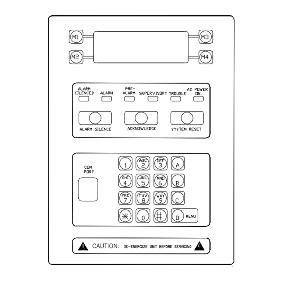
MPC-6000 / MPC-7000 / RND-2 INSTALLATION, OPERATION AND MAINTENANCE MANUAL APPENDIX-H: LCD, CONTROLS AND INDICATORS The MPC-6000/MPC-7000/RND-2 has a sounder, 6 LEDs, 4 navigational push buttons adjacent to the LCD display (M1-M4), 3 dedicated push buttons, alphanumeric keypad and communication port connector. -
Page 82: Alphanumeric Keypad
MPC-6000 / MPC-7000 / RND-2 INSTALLATION, OPERATION AND MAINTENANCE MANUAL The sounder operates as follows: SOUNDER Normally OFF – indicates that the system is in supervisory mode or all events in the system have been acknowledged. ON (steady) – indicates that at least ONE unacknowledged alarm is present in the system. - Page 83 MPC-6000 / MPC-7000 / RND-2 INSTALLATION, OPERATION AND MAINTENANCE MANUAL The events are displayed one at a time and cycle through a circular list once the first event or last event message is reached.
-
Page 84: Appendix-I: Output Features
MPC-6000 / MPC-7000 / RND-2 INSTALLATION, OPERATION AND MAINTENANCE MANUAL APPENDIX-I: OUTPUT FEATURES Output ON- and OFF- Time Delays Each output device has a selection for ON time delay and OFF time delay when it is installed in the configuration. The ON time delay refers to the delay in which the output will activate after the reception of its activation command. - Page 85 MPC-6000 / MPC-7000 / RND-2 INSTALLATION, OPERATION AND MAINTENANCE MANUAL The initiation of fan restart usage device during stand-by will annunciate a supervisory event that clears as soon as the input device reverts back to its stand-by state.
-
Page 86: Appendix-J: Pas/Pre-Signal
(typically a non-audible device) and starts a delay timer. When the delay timer elapses, the timeout group it is associated with is initiated and activates its audible outputs. The timeout group and delay timers are configurable. Refer to the MPC-6000/-7000/RND-2 Programming Manual, P/N 315-049403FA, for procedures in programming these features. - Page 87 MPC-6000 / MPC-7000 / RND-2 INSTALLATION, OPERATION AND MAINTENANCE MANUAL Pre-Signal When an alarm causing device in a Pre-Signal input group is initiated, the alarm condition is reported at the panel. Its timeout group outputs are not activated until the programmed investigation delay has elapsed regardless of annunciation of subsequent alarms and acknowledgement of alarms (see figure below).
-
Page 88: Appendix-K: Diagnostics Leds
MPC-6000 / MPC-7000 / RND-2 INSTALLATION, OPERATION AND MAINTENANCE MANUAL APPENDIX-K: DIAGNOSTIC LEDS The LEDs on the following boards are used for diagnostic purposes only. MPC6-MB / MPC6-MB2 DS3 – ON, indicates Low battery voltage or No battery detected. DS2 – ON, indicates High Battery voltage detected. -
Page 89: Appendix-L: Dact Information Overview
MPC-6000 / MPC-7000 / RND-2 INSTALLATION, OPERATION AND MAINTENANCE MANUAL APPENDIX-L: DACT INFORMATION OVERVIEW The DACT (Digital Alarm Communicator Transmitter) is an optional module for the MPC-6000, MPC-7000 and RND-2 control panels that allows transmission of event information to a remote receiver at a monitoring station using a dial-up modem connection. - Page 90 MPC-6000 / MPC-7000 / RND-2 INSTALLATION, OPERATION AND MAINTENANCE MANUAL To configure an event to be reported to Account 1 and Account 2, set it to Must report on both. If the event needs to be reported to either Account 1 or Account 2, set it to Can report on both.
- Page 91 MPC-6000 / MPC-7000 / RND-2 INSTALLATION, OPERATION AND MAINTENANCE MANUAL...
- Page 92 MPC-6000 / MPC-7000 / RND-2 INSTALLATION, OPERATION AND MAINTENANCE MANUAL...
-
Page 93: Appendix-M: Network Overview
MPC-6000 / MPC-7000 / RND-2 INSTALLATION, OPERATION AND MAINTENANCE MANUAL APPENDIX-M: NETWORK OVERVIEW The purpose of this section is to provide a general understanding of the network portion of this system. Basic Networking Principles The MPC networking system allows up to 99 panels or nodes to be connected in a network. - Page 94 They may be programmed with either the configuration tool or the firmware. A maximum of 255 network links may be used. Refer to the MPC-6000/MPC-7000/RND-2 Programming Manual, P/N 315-049403FA, for a detailed description of network links. When using a DACT, network links must be programmed for input groups to report to the DACT.
- Page 95 This option can only be configured in MPC-6000/-7000 networked panels. There are two programming options for Global Accept, “Yes” and “No”. • Setting this option to “Yes” allows a Networked panel (MPC-6000/-7000) to be silenced, acknowledged and reset from the RND-2.
-
Page 96: Appendix-N: Diagnostic Printer
(typically longer than 24 hours). The printers are used strictly for diagnostic purposes only. MPC-6000 / MPC-7000 printer connection Diagnostic printers are connected to the MPC-6000/ -7000 panels through terminal TB4 of its main board using an RS232 DB25 serial cable (serial cable is not provided). See Figure 1 below. - Page 97 MPC-6000 / MPC-7000 / RND-2 INSTALLATION, OPERATION AND MAINTENANCE MANUAL MPC-6000/-7000 panels can also be connected to a computer running terminal emulation software using an RS232 DB9 serial cable. Terminal emulation software is a communication program that is designed to emulate various types of text terminals configured to be connected through a modem or directory over a serial port.
- Page 98 MPC-6000 / MPC-7000 / RND-2 INSTALLATION, OPERATION AND MAINTENANCE MANUAL Following is an example of the Events Output on a HyperTerminal connection. Figure 3 Events Output when HyperTerminal is Connected Figure 4 Sensitivity Report on HyperTerminal (Refer to Programming Manual to access this feature)
- Page 99 MPC-6000 / MPC-7000 / RND-2 INSTALLATION, OPERATION AND MAINTENANCE MANUAL Figure 5 System History on HyperTerminal (Refer to the Programming Manual to access this feature) Network Printer A diagnostic printer can also be installed in a network. Refer to the Network Block diagram in Figure 6.
- Page 100 MPC-6000 / MPC-7000 / RND-2 INSTALLATION, OPERATION AND MAINTENANCE MANUAL Figure 7 12526A Connection to the Printer...
- Page 101 MPC-6000 / MPC-7000 / RND-2 INSTALLATION, OPERATION AND MAINTENANCE MANUAL To configure the printer NIB in the CIS-4 configuration tool, follow the steps listed below: 1. Power up the system. 2. Connect the programming cable between the laptop and the NIB.
-
Page 102: Appendix-O: Glossary
MPC-6000 / MPC-7000 / RND-2 INSTALLATION, OPERATION AND MAINTENANCE MANUAL APPENDIX-O: GLOSSARY 1st Alarm Condition. Refers to the condition in which the releasing or counting zone input group meets at least one of the threshold requirements. This does not refer to the pre-alarm condition detected by the smoke detector. - Page 103 MPC-6000 / MPC-7000 / RND-2 INSTALLATION, OPERATION AND MAINTENANCE MANUAL Detector - Thermal Type. An addressable thermal sensor that is programmable as either a fixed temperature (135° F) or as a rate of rise detector. Discharge Condition. Refers to the condition in which the releasing circuit is activated.
- Page 104 MPC-6000 / MPC-7000 / RND-2 INSTALLATION, OPERATION AND MAINTENANCE MANUAL Listed. Equipment or materials included in a list published by an organization acceptable to the authority having jurisdiction and concerned with product evaluation, that maintains periodic inspection of production of listed equipment or materials. And whose listing states either that the equipment or material meets appropriate standards or has been tested and found suitable for use in a specified manner.
- Page 105 MPC-6000 / MPC-7000 / RND-2 INSTALLATION, OPERATION AND MAINTENANCE MANUAL Supervisory Alarm. A signal indicating the operation of a supervisory device. Supervisory Device. A device that monitors the condition of a sprinkler system such as a gate-valve switch, water-level switch, low pressure switch, low temperature switch or fire pump monitor.
- Page 108 Siemens Building Technologies, Inc. 8 Fernwood Road • Florham Park, NJ 07932 Tel: (973) 593-2600 • Fax: (973) 593-6670 Web: www.faradayfirealarms.com P/N 315-447309-7 (12.07.07)
Need help?
Do you have a question about the MPC-6000 and is the answer not in the manual?
Questions and answers