
Related Manuals for Miller DIVERSION 165


Summary of Contents for Miller DIVERSION 165
- Page 1 OM-232 895F 2008−12 Processes Processes TIG (GTAW) Welding Description 230 Volt Arc Welding Power Source DIVERSION 165 230 Volt 60 Hz TIG Only File: TIG (GTAW) Visit our website at www.MillerWelds.com...
- Page 2 We know you don’t have time to do it any other way. That’s why when Niels Miller first started building arc welders in 1929, he made sure his products offered long-lasting value and superior quality.
-
Page 3: Table Of Contents
TABLE OF CONTENTS SECTION 1 − SAFETY PRECAUTIONS - READ BEFORE USING ........1-1. -
Page 5: Section 1 − Safety Precautions - Read Before Using
SECTION 1 − SAFETY PRECAUTIONS - READ BEFORE USING som _2007−04 Protect yourself and others from injury — read and follow these precautions. 1-1. Symbol Usage DANGER! − Indicates a hazardous situation which, if Indicates special instructions. not avoided, will result in death or serious injury. The possible hazards are shown in the adjoining symbols or explained in the text. - Page 6 D Do not use welder to thaw frozen pipes. FUMES AND GASES can be hazardous. D Remove stick electrode from holder or cut off welding wire at contact tip when not in use. Welding produces fumes and gases. Breathing D Wear oil-free protective garments such as leather gloves, heavy these fumes and gases can be hazardous to your shirt, cuffless trousers, high shoes, and a cap.
-
Page 7: Additional Symbols For Installation, Operation, And Maintenance
1-3. Additional Symbols For Installation, Operation, And Maintenance FIRE OR EXPLOSION hazard. MOVING PARTS can cause injury. D Do not install or place unit on, over, or near D Keep away from moving parts such as fans. combustible surfaces. D Keep all doors, panels, covers, and guards D Do not install unit near flammables. -
Page 8: California Proposition 65 Warnings
1-4. California Proposition 65 Warnings For Gasoline Engines: Welding or cutting equipment produces fumes or gases which contain chemicals known to the State of California to Engine exhaust contains chemicals known to the State of cause birth defects and, in some cases, cancer. (California California to cause cancer, birth defects, or other reproduc- Health &... -
Page 9: Section 2 − Consignes De Sécurité − Lire Avant Utilisation
SECTION 2 − CONSIGNES DE SÉCURITÉ − LIRE AVANT UTILISATION fre_som_2007−04 Se protéger et protéger les autres contre le risque de blessure — lire et respecter ces consignes. 2-1. Symboles utilisés DANGER! − Indique une situation dangereuse qui si on Indique des instructions spécifiques. - Page 10 Il reste une TENSION DC NON NÉGLIGEABLE dans LE SOUDAGE peut provoquer un in les sources de soudage onduleur quand on a cendie ou une explosion. coupé l’alimentation. Le soudage effectué sur des conteneurs fermés tel D Arrêter les convertisseurs, débrancher le courant électrique et que des réservoirs, tambours ou des conduites peu décharger les condensateurs d’alimentation selon les instructions provoquer leur éclatement.
-
Page 11: Dangers Supplémentaires En Relation Avec L'installation, Le Fonctionnement Et La Maintenance
D Protéger les bouteilles de gaz comprimé d’une chaleur excessive, ACCUMULATIONS des chocs mécaniques, des dommages physiques, du laitier, des risquent de provoquer des blessures flammes ouvertes, des étincelles et des arcs. ou même la mort. D Placer les bouteilles debout en les fixant dans un support station- D Fermer l’alimentation du gaz protecteur en cas naire ou dans un porte-bouteilles pour les empêcher de tomber ou de non-utilisation. -
Page 12: Proposition Californienne 65 Avertissements
LES FILS DE SOUDAGE peuvent LE RAYONNEMENT HAUTE FRÉ- provoquer des blessures. QUENCE (H.F.) risque de provoquer des interférences. D Ne pas appuyer sur la gâchette avant d’en avoir reçu l’instruction. D Le rayonnement haute fréquence (H.F.) peut D Ne pas diriger le pistolet vers soi, d’autres per- provoquer des interférences avec les équipe- sonnes ou toute pièce mécanique en enga- ments de radio−navigation et de communica-... -
Page 13: Principales Normes De Sécurité
2-5. Principales normes de sécurité Safety in Welding, Cutting, and Allied Processes, ANSI Standard Z49.1, L4W 5NS (téléphone : 800-463-6727 ou à Toronto 416-747-4044, site de Global Engineering Documents (téléphone : 1-877-413-5184, site Internet : www.csa-international.org). Internet : www.global.ihs.com). Safe Practice For Occupational And Educational Eye And Face Protec- tion, ANSI Standard Z87.1, de American National Standards Institute, Recommended Safe Practices for the Preparation for Welding and Cut- 11 West 43rd Street, New York, NY 10036-8002 (téléphone :... - Page 14 OM-232 895 Page 10...
-
Page 15: Section 3 − Specifications
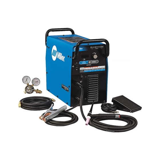
SECTION 3 − SPECIFICATIONS 3-1. Included with Your Unit Welding Power Source 5 ft (1.5 m) Primary Cord With Plug Gas Hose Gas Regulator 12 ft (3.7 m) Work Cable With Clamp Air-Cooled 150 Amp TIG Torch with 12 ft (3.7 m) Cable Some assembly is required. -
Page 16: Dimensions And Weights
3-4. Dimensions And Weights Dimensions 23-15/16 in (608 mm) 17 in Height 17 in. (433 mm) (432 mm) Width 9.88 in. (251 mm) 23.93 in. (608 mm) w/handles Length 19.25 in. (489 mm) w/o handles 9-7/8 in (251 mm) Ref. 805 114-A Weight 50 lbs (23 kg) 3-5. -
Page 17: Section 4 − Installation
SECTION 4 − INSTALLATION 4-1. Selecting A Location Handles Use Handles to lift welder; get help if necessary. Cart Movement Place welder on cart to move unit. Line Disconnect Device Locate unit near correct input pow- er supply. Position unit so air can circulate. For information about sources of high-frequency see Section 8. -
Page 18: Shielding Gas Connections
4-3. Shielding Gas Connections Use argon shielding gas for best performance. Cylinder Valve Open valve slightly so gas flow blows dirt from valve. Close valve. Tools Needed: Regulator/Flow Gauge 5/8, 1-1/8 in Connect regulator/flow gauge to gas cylinder. Do not overtighten. Connect gas hose to gas in fitting. -
Page 19: Connecting Input Power
4-5. Connecting Input Power Installation must meet all Na- tional and Local Codes − have only qualified persons make this installation. Disconnect and lockout/tag- out input power before con- necting input conductors from unit. Always connect green or green/yellow conductor 18 in (457 mm) of supply grounding terminal space for airflow... -
Page 20: Section 5 − Operation
SECTION 5 − OPERATION 5-1. Controls Material Switch Do not use AC output in damp areas, if movement is confined, or if there is danger of falling. Use AC output ONLY if required for the welding process, and then use a remote control. Do not change position of switch while welding or while under load. - Page 21 Torch Torch Operation: Amperage Adjustment Wheel Use wheel to adjust amperage from ten amps to maximum value set on the machine’s Material Thickness/ Amperage Control. On/Off Switch Switch has three features that con- trol the machine in different ways: • Trigger hold − Push and release On/Off switch to start welding.
-
Page 22: Section 6 − Maintenance And Troubleshooting
SECTION 6 − MAINTENANCE AND TROUBLESHOOTING 6-1. Routine Maintenance Disconnect power before maintaining. Maintain more often during severe conditions. n = Check Z = Change ~ = Clean Δ = Repair l = Replace * To be done by Factory Authorized Service Agent Every Months nl Labels... -
Page 23: Troubleshooting
6-3. Troubleshooting The remedies listed below are recommendations only. If these remedies do not fix the trouble with your unit, have a Factory Authorized Service Agent check unit. There are no user serviceable parts inside unit. Trouble Remedy No weld output; unit completely Place machine power switch in On position (see Section 5-1). -
Page 24: Section 7 − Electrical Diagram
SECTION 7 − ELECTRICAL DIAGRAM 232 891-D Figure 7-1. Circuit Diagram OM-232 895 Page 20... -
Page 25: Section 8 − High Frequency
SECTION 8 − HIGH FREQUENCY 8-1. Welding Processes Requiring High Frequency High-Frequency Voltage TIG − helps arc jump air gap between torch and workpiece and/ or stabilize the arc. Work high_freq 7/05 − S-0693 8-2. Incorrect Installation Weld Zone 11, 12 50 ft (15 m) Sources of Direct High-Frequency... -
Page 26: Correct Installation
8-3. Correct Installation Weld Zone 50 ft (15 m) 50 ft (15 m) Ground all metal ob- jects and all wiring in welding zone using #12 AWG wire. Ground workpiece if required by codes. Nonmetal Building Metal Building High-Frequency Source (welding Conduit Joint Bonding and Grounding Metal Building Requirements power source with built-in HF or... -
Page 27: Section 9 − Selecting And Preparing A Tungsten For Dc Or Ac Welding With Inverter Machines
SECTION 9 − SELECTING AND PREPARING A TUNGSTEN FOR DC OR AC WELDING WITH INVERTER MACHINES gtaw_Inverter_2007−05 Whenever possible and practical, use DC weld output instead of AC weld output. 9-1. Selecting Tungsten Electrode ( Wear Clean gloves To Prevent Contamination Of Tungsten ♦... -
Page 28: Section 10 − Guidelines For Tig Welding (Gtaw)
SECTION 10 − GUIDELINES FOR TIG WELDING (GTAW) 10-1. Positioning The Torch Grinding the tungsten electrode produces dust and flying sparks which can cause injury and start fires. Use local exhaust (forced ventilation) at the grinder or wear an approved respirator. Read MSDS for safety information. -
Page 29: Torch Movement During Welding
10-2. Torch Movement During Welding Tungsten Without Filler Rod ° Welding direction Form pool Tilt torch Move torch to front of pool. Repeat process. Tungsten With Filler Rod ° ° Welding direction Form pool Tilt torch Add filler metal Remove rod Move torch to front of pool. -
Page 30: Section 11 − Parts List
SECTION 11 − PARTS LIST 805 115-B Figure 11-1. Main Assembly OM−232 895 Page 26... - Page 31 232 896 Nameplate, Miller Diversion 165 ........
- Page 32 Hardware is common and not available unless listed. 805 135-B Figure 11-2. Windtunnel Assembly Item Dia. Part Mkgs. Description Quantity 232 922 Figure 11-2. Windtunnel Assembly (Figure 11-1, Item 15) ..230 144 Circuit Card Assy, Commutator Control .
- Page 33 Hardware is common and not available unless listed. 805 123-A Figure 11-3. Heat Sink, Secondary Assembly Item Dia. Part Mkgs. Description Quantity 232 917 Figure 11-3. Heat Sink, Secondary Assembly (Figure 11-2, Item 7) ... . 232 869 Heat Sink, Secondary .
- Page 34 Notes...
- Page 35 Effective January 1, 2008 (Equipment with a serial number preface of LJ or newer) This limited warranty supersedes all previous Miller warranties and is exclusive with no other Warranty Questions? guarantees or warranties expressed or implied. LIMITED WARRANTY − Subject to the terms and conditions...
-
Page 36: Options And Accessories
Contact the Delivering Carrier to: File a claim for loss or damage during shipment. For assistance in filing or settling claims, contact your distributor and/or equipment manufacturer’s Transportation Department. © PRINTED IN USA 2008 Miller Electric Mfg. Co. 2008−01...
Need help?
Do you have a question about the DIVERSION 165 and is the answer not in the manual?
Questions and answers