TSC ME240 Service Manual
Thermal transfer / direct thermal bar code printer
Hide thumbs
Also See for ME240:
- User manual (85 pages) ,
- Quick installation manual (2 pages) ,
- Programming manual (434 pages)
Table of Contents
Advertisement
Advertisement
Table of Contents

Related Manuals for TSC ME240


Summary of Contents for TSC ME240
- Page 1 ME240/ ME340 THERMAL TRANSFER / DIRECT THERMAL BAR CODE PRINTER SERVICE MANUAL...
-
Page 2: Table Of Contents
TABLE OF CONTENT 1. FUNDAMENTAL OF THE SYSTEM ................1 1.1. Overview ......................... 1 2. ELECTRONICS ......................5 2.1 Summary of Board Connectors ................5 2.2 Pin Configuration ....................9 3. MECHANISM ......................11 3.1 Remove the Electronics Cover ................11 3.2 Remove the Right Side Cover ................ -
Page 3: Fundamental Of The System
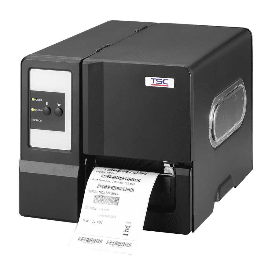
1. FUNDAMENTAL OF THE SYSTEM 1.1. Overview Front View 1. LED indicators 2. Pause key 3. Feed key 4. Paper exit chute 5. Lower front cover 6. Media viewer 7. Printer right side cover opener 8. LCD (Option) 9. Keys for LCD module (Option) -
Page 4: Interior View
Interior View 1. Ribbon rewind spindle 2. Ribbon supply spindle 3. Print head pressure adjustment knob 4. Ribbon end sensor 5. Print head release lever 6. Label roll guard 7. 3” core adapter 8. Label supply spindle 9. Ribbon guide bar 10. -
Page 5: Rear View
Rear View 1. Internal Ethernet interface (Option) 2. Fan-fold paper entrance chute 3. RS-232C interface (Max. 115,200 bps) 4. USB interface (USB 2.0/ Full speed mode) *5. SD card slot 6. Centronics interface (Option) 7. USB host (Option) 8. Power switch 9. - Page 6 V1.0, V1.1 microSD 1 GB Transcend, Panasonic V2.0 SDHC CLASS 4 microSD 4 GB Panasonic V2.0 SDHC CLASS 6 microSD 4 GB Transcend V1.0, V1.1 miniSD 128 MB Transcend, Panasonic V1.0, V1.1 miniSD 256 MB Transcend, Panasonic V1.0, V1.1 miniSD 512 MB Transcend, Panasonic V1.0, V1.1 miniSD 1 GB...
-
Page 7: Electronics
2. ELECTRONICS 2.1 Summary of Board Connectors Main board... - Page 8 Connector Description USB connector RS-232C connector SD card slot Ethernet RJ-45 connector (Option) USB host connector (Option) Micro processor Head open sensor connector Description Voltage Head open sensor emitter 1.2~1.4V power pin Head open sensor 0V: Head close receiver 3.3V: Head open RFID module connector Recovery connector Ribbon near end sensor connector...
- Page 9 Description Voltage Ribbon sensor receiver A/D: 0~3.3V Ribbon sensor emitter power pin 4.0~4.1V: Emitter on Ribbon sensor emitter 4.3~4.4V: Emitter off Cutter/peel-off sensor connector Description Voltage Cutter power 4.0~4.1V: Emitter on Peel sensor emitter 4.3~4.4V: Emitter off Logic power Cutter position sensor 0V: Cutter stop switch 3.3V: Cutter work...
- Page 10 Centronics-interface board Connector Description Remark Centronics soft cable connector Centronics power connector Centronics port connector...
-
Page 11: Pin Configuration
2.2 Pin Configuration RS-232C CONFIGURATION +5 V CONFIGURATION Centronics SPP Mode Nibble In/Out Strobe Data 0-7 Busy Paper Out / End Select Ground No Defined 16-17 Ground No Defined 19-30 Ground No Defined Error / Fault 33-35 Ground No Defined... - Page 12 Ethernet CONFIGURATION...
-
Page 13: Mechanism
3. MECHANISM 3.1 Remove the Electronics Cover 1. Remove three screws on back of the printer. Screws 2. Open printer right side cover and remove one screw then close the cover. Screws 3. Remove the electronics cover. Electronics cover 4. Reassemble the parts in the reverse procedures. -
Page 14: Remove The Right Side Cover
3.2 Remove the Right Side Cover 1. Open printer right side cover and remove four screws to remove the printer right side cover. 2. Reassemble the parts in the reverse procedures. Screws Screws... -
Page 15: Replacing The Key/Lcd Panel Module
3.3 Replacing the Key/LCD Panel Module 1. Refer to section 3.1 to remove the electronics cover. 2. Disconnect harness from the Key/LCD panel module. 3. Push two tabs to remove/replace the Key/LCD panel module. Key Panel Module LCD Panel Module (Option for Basic model) PUSH... -
Page 16: Replacing The Main Board
3.4 Replacing the Main Board 1. Refer to section 3.1 to remove electronics cover. 2. Remove two screws on the power jack socket then pull out the socket. 3. Disconnect all connectors from the main board. Note: You should press the tab of power supply harness when disconnect the power supply connector. - Page 17 4. Remove four screws on the main board. Screws Screws 4. Replace the main board. 5. Reassemble the parts in the reverse procedures.
-
Page 18: Replacing The Power Supply Unit
3.5 Replacing the Power Supply Unit 1. Refer to section 3.4 to remove the main board. 2. Disconnect two connectors from the power switch. 3. Take off the power supply cover (black mylar). Disconnect two connectors and remove four screws on the power supply unit. Screws Screws 3. -
Page 19: Replacing The Stepping Motor
3.6 Replacing the Stepping Motor 1. Refer to section 3.1 to remove the electronics cover. 2. Disconnect the stepping motor connector. Stepping motor connector 3. Remove three screws on the stepping motor. Screws 4. Replace the stepping motor. 5. Reassemble the parts in the reverse procedures. -
Page 20: Replacing The Platen Roller Assembly
3.7 Replacing the Platen Roller Assembly 1. Open printer right side cover. 2. Disengage the print head lift lever. 3. Remove one screw to remove the lower front cover. Lower front cover Screw 4. Remove one screw on the platen right side bushing. Screws 5. - Page 21 6. Take out the platen bushing, platen roller assembly and replace a new platen roller assembly. Right side bushing Platen roller assembly 7. Reassemble the parts in the reverse procedures. Note: For regular label For thick label (Thickness is 0.19 mm)
-
Page 22: Replacing The Print Head Ass'y
3.8 Replacing the Print head ASS'Y 1. Open the printer right side cover. 2. Remove one screw from the mechanism. Screws 3. Disengage the print head release lever. 4. Carefully disconnect the print head connector from the print head module. 5. - Page 23 6. Connect the print head cable and carefully slide assembly into the print mechanism. The holes of print head assembly must align and then insert the tenons of print mechanism. Tenons Print head module 7. Close the print head release lever. Use the new screw to install the new print head module.
-
Page 24: Replacing The Media Sensor Module
3.9 Replacing the Media Sensor Module 1. Refer to section 3.1 to remove the electronics cover. 2. Disconnect the media sensor module connector from the main board. Media sensor module connector 3. At the bottom of the media sensor module, there is a green plastic tab to latch the sensor module to the mechanism. -
Page 25: Replacing The Ribbon End Sensor Module
3.10 Replacing the Ribbon End Sensor Module 1. Refer to section 3.1 to remove the electronics cover. 2. Disconnect the ribbon end sensor module connector from the main board. Ribbon end sensor module connector 3. Remove two screws to remove the ribbon end sensor module. Screws 6. -
Page 26: Replacing The Ribbon Encoder Sensor Module
3.11 Replacing the Ribbon Encoder Sensor Module 1. Refer to section 3.1 to remove the electronics cover. 2. Disconnect the ribbon encoder sensor module connector from the main board. Ribbon encoder sensor module connector 3. Remove one screw that fixing the ribbon supply spindle. Screw 6. - Page 27 7. Remove one screw to replace the ribbon encoder sensor module. Screw 8. Reassemble the parts in the reverse procedures.
-
Page 28: Centronics Parallel Interface Board Installation (Option)
3.12 Centronics Parallel Interface Board Installation (Option) 1. Refer to section 3.1 to remove the electronics cover. 2. Remove two screws to remove the interface cover. Screws 3. Use two screws to fix the Centronics parallel interface board on the rear of printer. Screws 4. - Page 29 5. Loosen the connector before install the flat cable. 6. Connect the flat cable between the Centronics parallel interface board and the main board. 7. Connect the 5-pin cable between the Centronics parallel interface board and main board. 8. Reassemble the parts in the reverse procedures.
-
Page 30: Cutter Module Installation (Option)
3.13 Cutter Module Installation (Option) 1. Open printer right side cover. 2. Remove one screw to remove the lower front cover. Lower front cover Screw 3. Thread the cutter cable through the bottom of lower print mechanism. Lower print mechanism Cutter module cable 4. - Page 31 5. Use enclosed two screws to fix the cutter fixing plate onto the lower print mechanism. 6. Close the cutter cover.
-
Page 32: Peel-Off Module Installation (Option)
3.14 Peel-off Module Installation (Option) 1. Open printer right side cover. 2. Remove one screw to remove the lower front cover. Lower front cover Screw 3. Thread the peel-off module cable through the bottom of lower print mechanism. Lower print mechanism Peel-off module cable 4. - Page 33 5. Use enclosed two screws to fix the peel-off fixing plate onto the lower print mechanism. 6. Close the peel-off cover.
-
Page 34: Print Engine Module Specification (Option)
3.15 Print Engine Module Specification (Option) Print engine module measurements -Print engine module -Print engine module with peel-off... -
Page 35: Bottom View
-Print engine module with cutter Bottom view Note: 1. All measurements are in mm. There are 3 fastenings in this print engine module, the fastening location be marked in blue on bottom view drawing, fits with screw M4*10L. -
Page 36: Troubleshooting
4. TROUBLESHOOTING 4.1 Common Problems The following guide lists the most common problems that might be encountered when operating this bar code printer. If the printer still does not function after all suggested solutions have been invoked, please contact the Customer Service Department of your purchased reseller or distributor for assistance. - Page 37 * Re-connect cable to interface. * If using serial cable, - Please replace the cable with pin to pin connected. - Check the baud rate setting. The default baud rate setting of printer is 9600,n,8,1. * If using the Ethernet cable, - Check if the Ethernet RJ-45 connector green LED is lit on.
- Page 38 * Reload the supply. * Clean the print head. * Clean the platen roller. * Adjust the print density and print speed. * Run printer self-test and check the print head test pattern if there is dot missing in the pattern. * Change proper ribbon or proper label media.
- Page 39 * Label size is not specified * Check if label size is setup correctly. properly. * Calibrate the sensor by Auto Gap or * Sensor sensitivity is not set Manual Gap options. Skip labels when printing properly. * Clear the GAP/Black-mark sensor by * The media sensor is covered with blower.
-
Page 40: Print Head Pressure Adjustment Knob
4.2 Print Head Pressure Adjustment Knob There are two conditions that will need to adjust the print head pressure. 1. Print with thick media If the media thickness is larger than 0.19 mm, the larger pressure is required to get good quality printout. -
Page 41: Mechanism Fine Adjustment To Avoid Ribbon Wrinkles
4.3 Mechanism Fine Adjustment to Avoid Ribbon Wrinkles This printer has been fully tested before delivery. There should be no ribbon wrinkle presented on the media for general-purpose printing application. Ribbon wrinkle is related to the media thickness, print head pressure balance, ribbon film characteristics, print darkness setting…etc. - Page 42 Adjust the print head pressure adjustment knob Adjust the print head pressure adjustment knob Left knob Right knob The print head pressure adjustment knob has 5 The print head pressure adjustment knob has 5 levels of settings. Clockwise direction adjustment levels of settings.
-
Page 43: Z-Axis Mechanism Adjustment Knob
4.4 Z-axis Mechanism Adjustment Knob Z-axis mechanism adjustment knob Marker position For narrow media, If change the print head pressure adjustment knob setting can’t get the printout without ribbon wrinkle, the Z-axis mechanism adjustment knob should be adjusted to get the satisfied printout. This Z-axis mechanism adjustment knob is used to find tune the right side pressure of print head. - Page 44 2. Please be noted that print head right pressure find turn should be done by try-and-error. Rotate the Z-axis mechanism adjustment knob for a few circles by wrench and print again to check if the ribbon wrinkle remains. If the wrinkle still remains, please turn the Z-axis mechanism adjustment knob clockwise about 1/4 circle each time for adjustment.
-
Page 45: Maintenance
5. MAINTENANCE This session presents the clean tools and methods to maintain your printer. 1. Please use one of following material to clean the printer. Cotton swab (Head cleaner pen) Lint-free cloth Vacuum / Blower brush 100% ethanol 2. - Page 46 Note: Do not touch printer head by hand. If you touch it careless, please use ethanol to clean Please use 100% Ethenol. DO NOT use medical alcohol, which may damage the printer head. Regularly clean the print head and supply sensors once change a new ribbon to keep printer performance and extend printer life.
-
Page 47: Update History
UPDATE HISTORY Date Content Editor 2012/6/14 Add section 3.15 for print engine module info Camille 2012/9/28 Modify section 3.13 and 3.14 Camille... - Page 49 9F., No.95, Minquan Rd., Xindian Dist., No.35, Sec. 2, Ligong 1st Rd., Wujie Township, New Taipei City 23141, Taiwan (R.O.C.) Yilan County 26841, Taiwan (R.O.C.) TEL: +886-2-2218-6789 TEL: +886-3-990-6677 FAX: +886-2-2218-5678 FAX: +886-3-990-5577 Web site: www.tscprinters.com E-mail: printer_sales@tscprinters.com TSC Auto ID Technology Co., Ltd. tech_support@tscprinters.com...
Need help?
Do you have a question about the ME240 and is the answer not in the manual?
Questions and answers