Glow-worm Ultracom 18sxi Installation And Servicing
High efficiency
condensing system
boilers
Hide thumbs
Also See for Ultracom 18sxi:
- Installation and servicing manual (64 pages) ,
- Instructions for use installation and servicing (48 pages) ,
- Installation and servicing (60 pages)

Related Manuals for Glow-worm Ultracom 18sxi


Summary of Contents for Glow-worm Ultracom 18sxi
-
Page 1: Installation And Servicing
Ultracom Installation and Servicing 18sxi G.C. No. 41-019-07 30sxi G.C. No. 41-019-08 High Efficiency Condensing System Boilers www.glow-worm.co.uk... -
Page 2: Guarantee Registration
Guarantee Registration Thank you for installing a new Glow-worm appliance in your home. Glow-worm appliances are manufactured to the very highest standard so we are pleased to offer our customers a Comprehensive Guarantee. This product is guaranteed for 24 months from the date of installation or 30 months from the date of manufacture, whichever is the shorter, for parts and labour. -
Page 3: Table Of Contents
These instructions consist of, Installation, Servicing, Fault Finding, Replacement of Parts and Spares. The instructions are an integral part of the appliance and must, to comply with the current issue of the Gas Safety (Installation and Use) Regulations, be handed to the user on completion of the installation. -
Page 4: Warnings
- Grip the boiler at its base worm. - Be physically capable Any alteration not approved by Glow-worm, could invalidate the certification, boiler warranty and may also infringe the - Use safety clothing where appropriate, e.g. gloves, safety current issue of the statutory requirements. -
Page 5: Statutory Requirements
Statutory Requirements CE Mark NOTE: For further information, see the current issue of the Building Regulations, approved document L1 ( in the UK) and This boiler meets the requirements of Statutory Instrument, the following current issues of: No. 3083 The Boiler (Efficiency) Regulations, and therefore is 1) Central heating system specification (CheSS) deemed to meet the requirements of Directive 92/42/EEC on the efficiency requirements for new hot water boilers fired with... -
Page 6: Boiler Design
This valve must not be touched. Should there be any discharge from the pipe, isolate the boiler electrical supply and call your installer or Glow-worm’s own service organisation using the telephone number on the inside front cover of this booklet. -
Page 7: Boiler Specification
1 Boiler Specification BOILER SPECIFICATION 18sxi 30sxi Lift weight 36kg (80Ib) 39kg (86Ib) Total weight (installed) 41kg (90Ib) 44.5kg (98Ib) Gas connection 15mm copper 15mm copper Heating flow & return connection Ø O.D. 22mm. copper 22mm. copper Condensate connection Ø I.D. 21.5mm. -
Page 8: Boiler Dimensions & Hydraulic Schematic
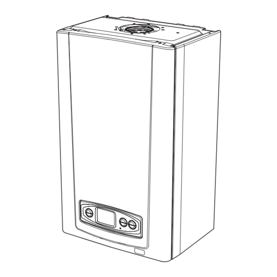
2 Boiler Dimensions and Hydraulic Schematic Diagram 2.2 2.1 Boiler Dimensions & Hydraulic Schematic All dimensions are given in millimetres (except as noted). The general arrangement of the boiler is shown in diagram 2.1. and the hydraulic and gas schematic, diagram 2.2. Diagram 2.1 The data label is positioned on the front of the inner casing panel. -
Page 9: Boiler Location, Clearances And Ventilation
If the boiler is to be installed in a timber frame building it should be fitted in accordance with the Institute of Gas Engineers document IGE/UP/7/1998. If in doubt seek advice from local gas undertaking or Glow-worm. 3.4 Combustible Material Diagram 3.1... -
Page 10: Flue Options And Terminal Clearances
4 Flue Options and Terminal Clearances Ridge Tile Terminal Part No. A2043800 - Section 10, page 29 Top horizontal standard flue (Ø60/100) Top horizontal telescopic flue (Ø60/100) Part No. A2043400 - Section 10, page 23 Part No. A2043600 - Section 10, page 19 Plume Management Kit basic set, white, concentric flue (Ø60/100) - Part No. -
Page 11: Flue Terminal Position
4 Flue Options and Terminal Clearances 4.1 Flue Options There are various flue options to choose from as illustrated in diagram 4.1. The flue lengths and installation are described in section 10. 4.2 Flue Terminal Position In GB the minimum acceptable siting dimensions for the terminal from obstructions, other terminals and ventilation openings are shown in diagram 4.2. -
Page 12: Water System 5
5 Water System 5.1 General This boiler is designed for use as part of a sealed water central heating system with fully pumped circulation. The pump, expansion vessel and associated safety devices are all fitted within the boiler. An options board accessory is available to link the internal programmer with a Honeywell S or Y plan system. - Page 13 5 Water System Diagram 5.2...
-
Page 14: Installation Preparation
6 Installation Preparation 6.1 Appliance Pack 6.3 Wall Template Please check the contents of packs as shown in diagram 6.1. Take the wall template from the document pack located within The packs are located in the top polystyrene packing. the top polystyrene packing and place in the desired position on the wall, giving due consideration to the required boiler Remove the carton sleeve and top pack then lift the boiler and... -
Page 15: Boiler Fixing
6 Installation Preparation 6.4 Flue Hole Cutting External access flue installation can use a 105mm diameter core drill. Internal access only flue installation will need a 125mm diameter core drill. NOTE: The flue is designed with an internal fall of 44mm/ metre (2.5°), therefore the hole can be drilled horizontally. -
Page 16: Gas/Water Connection
8 Gas / Water Connection 8.1 Systems Connection Remove the protective caps from the boiler connections. NOTE: The appliance may contain a small amount of water, place a water container beneath the boiler connections. Assemble and secure the pre formed copper tails to their respective isolation valves making sure of their correct orientation, see diagram 8.1. -
Page 17: Safety Discharge Valve And Condensate Connections
9 Safety Discharge Valve and Condensate Connections 9.1 Safety Discharge Valve Take the safety discharge pipe, supplied in the pipe pack and the union nut and seal, supplied in the loose items pack and fit as shown in diagram 9.1. This must be extended, using not less than 15mm o.d. - Page 18 9 Safety Discharge Valve and Condensate Connections Diagram 9.3...
-
Page 19: Flue Length Preparation And Installation
10 Telescopic Flue - Length, Preparation and Installation 10.1 Flue Length Multiple Boiler Chimney Flue Length The maximum permissible horizontal flue length is 10 metres The flue length must be calculated and installed according to plus the flue terminal assembly, this can be achieved by use the relevant standards EN 13384-1 and 2 (C43 flue systems of the accessories, see diagram 10.3. - Page 20 10 Telescopic Flue - Length, Preparation and Installation Diagram 10.2 Diagram 10.3...
- Page 21 10 Telescopic Flue - Length, Preparation and Installation 10.2 Horizontal Telescopic Flue - A2043600 Refer to diagram 10.2 for kit contents. 10.3 REAR Flue If a wall thickness is between 203mm min. to 413mm max. then the flue can be used without extensions. With the flue elbow temporarily fitted, measure the distance from the outside wall to the butt joint, see diagram 10.4.
- Page 22 10 Telescopic Flue - Length, Preparation and Installation 10.5 Flue Fitting IMPORTANT:- The flue seals are sensitive to mineral oil based lubricants. Do not grease the seals. If the seals do need to be lubricated use only water. During the installation of the flue system, ensure that debris such as mortar, filings or swarf are cleared from the flue system before completion.
- Page 23 10 Standard Flue - Length, Preparation and Installation 10.6 Flue Length Standard Horizontal Flue The maximum permissible horizontal flue length is 10 metres plus the flue terminal assembly, this can be achieved by use of the accessories, see diagram 10.12. However should additional 87.5 o or 2 x 45 o elbows be used then the length MUST be reduced by 1metre.
- Page 24 10 Standard Flue - Length, Preparation and Installation Diagram 10.11 Diagram 10.12...
- Page 25 10 Standard Flue - Length, Preparation and Installation 10.7 Standard Horizontal Flue - A2043400 Refer to diagram 10.11 for kit contents. 10.8 REAR Flue With the flue elbow temporarily fitted, measure the distance from the outside wall to the butt joint, see diagram 10.13. If the measurement ‘Y’...
- Page 26 10 Standard Flue - Length, Preparation and Installation 10.10 Flue Fitting IMPORTANT:- The flue seals are sensitive to mineral oil based lubricants. Do not grease the seals. If the seals do need to be lubricated use only water. During the installation of the flue system, ensure that debris such as mortar, filings or swarf are cleared from the flue system before completion.
- Page 27 10 Vertical Flue - Length, Preparation and Installation 10.11 Vertical flue Alternatively use 45º bends to avoid horizontal runs, see (b) in diagram10.18. The vertical flue system is available as an option where the The terminal siting should be as shown in diagram 4.2. boiler position does not permit the use of the top horizontal flue system.
-
Page 28: Flue Installation
10 Vertical - Flue Length, Preparation and Installation Flue Installation IMPORTANT:- The flue seals are sensitive to mineral oil based lubricants. Do not grease the seals. If the seals do need to be lubricated use only water. During the installation of the flue system, ensure that debris such as mortar, filings or swarf are cleared from the flue system before completion. - Page 29 10 Vertical - Flue Length, Preparation and Installation Ridge Tile Terminal A ridge tile terminal is available - part no. A2043800, see diagram 10.20. The installation of a ridge tile will be required. A suitable ridge tile is manufactured by: - Aspect East Anglia Limited The Old Mill East Harling...
- Page 30 10 Vertical Flue - Length, Preparation and Installation Completion of Installation With the flue terminal positioned in the roof the length of the final pipe can be determined. If a telescopic length cannot be used, then a standard flue length can be cut to make the correct length.
- Page 31 10 Twin Flue - Length, Preparation and Installation Secure long flue lengths (horizontal & vertical) to walls or ceiling at every joint or on straight flue runs at every joint and every metre flue run. Diagram 10.25...
-
Page 32: Terminal Position
10 Twin Flue - Length, Preparation and Installation 10.12 Twin flue The twin flue system is available as an option when the top horizontal or vertical flue system is not appropriate. The system can provide an independent horizontal air inlet and flue outlet, horizontal air inlet and vertical flue outlet or vertical air inlet and flue outlet via a concentric terminal. -
Page 33: Installation Details
10 Twin Flue - Length, Preparation and Installation Installation Details The parts available for a twin flue system installation are shown in diagram 10.26. Boiler Connection IMPORTANT: The flue seals are sensitive to mineral oil based lubricants. Do not grease the seals. If the seals do need to be lubricated use only water. - Page 34 2 x 45 bends the maximum length of the Plume Management Kit must be reduced by 1m. For more information contact Glow-worm, refer to page 2. The Plume Management Kit is supplied with installation instructions. Refer to BS5546 or BS6798 for advice on disposal of boiler condensate.
-
Page 35: Electrical Connection
● The boiler is suitable for installation in bathroom zones 2 and 3. 11.1 Electrical Wiring If you are fitting the Glow-worm Options Board Kit, please refer to the instructions supplied with the kit for the system wiring. Remove the electrical cartridge from the fittings pack. -
Page 36: Commissioning
11 Electrical Connection 11.2 System Controls 24V WARNING: UNDER NO CIRCUMSTANCES MUST ANY MAINS VOLTAGE BE APPLIED TO ANY OF THE TERMINALS ON THE 24V CONNECTION PLUG. Connect the mains supply and system heating controls e.g. room thermostat as diagram 11.2. External controls should be fitted in accordance with the rules in force. -
Page 37: Gas Supply
DRAIN POINTS No. 01773 828100. LPG Conversion: See section 12.9. NOTE: If you have fitted a Glow-worm Options Board Kit, please refer to the instructions supplied with the kit for completion of commissioning. Do not operate the boiler without water. - Page 38 12 Commissioning Additionally the safe nominal maximum heat input of the appliance can be achieved at an inlet pressure down to 15mbar. NOTE: The BURNER PRESSURE cannot be measured and is not used to measure the gas rate. Gas Rate Make sure that ALL other gas burning appliances and pilot lights are off.
-
Page 39: Instruct The User
12 Commissioning 12.8 Instruct the User ● Demonstrate, then instruct the User about the lighting procedure and heating system controls operation. ● Advise the user on the use and maintenance of any scale reducer and pass on any relevant instructional documents. ●... - Page 40 As an option, a chargeable boiler only commissioning service throttle screw (anti- clockwise to increase), see diagram can be provided by Glow-worm Service by calling telephone 12.5 no more than 1/8 of a turn, waiting a minute to allow No. 01773 828100.
-
Page 41: Servicing
When replacing a part on this appliance, use only spare parts that you can be assured conform to the safety and performance specification that we require. Do not use reconditioned or copy parts that have not been clearly authorised by Glow-worm. If any electrical connections have been disconnected and after their connection, checks to the earth continuity, polarity, short circuit and resistance to earth must be repeated using a suitable multimeter, as described in section 14. -
Page 42: Combustion Ratio
CO/CO2 ratio “default display” this will indicate the boiler has been forced to is acceptable. Advice can be sought from the Glow-worm maximum. Wait until the CO2 value is stable and check that Technical Helpline. -
Page 43: Spark Electrode
13 Servicing 13.2 Spark Electrode 13.3 Burner Disconnect the spark electrode plug and earth lead, see NOTE: diagram 13.5. Remove the two securing screws and withdraw ● The following procedure will require that you replace the the spark electrode carefully from the combustion chamber, burner door seal and nyloc nuts. -
Page 44: Inner Casing Panel Seal Check
13 Servicing Diagram 13.7 13.4 Combustion Chamber and Heat Exchanger Remove loose debris from inside the heat exchanger using a soft brush and vacuum cleaner. Carefully flush by spraying water into the heat exchanger, any remaining debris should pass through the condensate trap (Ensure the water is kept away from electrical components). -
Page 45: Fault Finding
14 Fault Finding 14.1 Preliminary fault finding The following checks should be performed before proceeding onto specific diagnostics: • Check the external electrical supply to the boiler is on and a supply of 230V is present at the ‘L’ and ‘N’ terminals on the installer interface, refer to section 11.4 for access and diagram 14.4. - Page 46 14 Fault Finding CONTROL VALVE IGNITION HEATING ELECTRODE RETURN IGNITER THERMISTOR UNIT HEATING FLOW THERMISTOR WATER PRESSURE SENSOR PUMP CHASSIS EARTH MAIN CONTROL BOARD BROWN BLUE GREEN/YELLOW GREY BLACK APPLIANCE YELLOW INTERFACE BOARD WHITE ORANGE PURPLE Diagram 14.4...
- Page 47 14 Fault Finding CENTRAL HEATING Diagram 14.5...
- Page 48 14 Fault Finding Fault Codes If -9 C is displayed, check that the thermistor wires are unconnected, faulty or trapped. Diagram 14.6...
- Page 49 14 Fault Finding Fault Codes (continued) Diagram 14.6 Diagnostic Menu Use the ‘+’ or ‘-’ buttons to view the appropriate diagnostic number, see diagram 14.7. The Diagnostic Menu provides the ability to view and change certain parameters. If necessary the values can be changed by: See Diagram 14.7 for available parameters.
- Page 50 14 Fault Finding Diagnostic Menu - Level 1 Installer Access (see State Lists table) Indicates read and write function - all other diagnostics are read only Diagram 14.7...
- Page 51 14 Fault Finding State list - Accessed through Diagnostic Codes - Level 1, Installer Access d.99 STATE LISTS Central heating mode (Priority 3) Possible Causes S.00 no heating required S.01 fan pre-run S.02 pump pre-run S.03 ignition S.04 burner on S.05 pump / fan overrun S.06...
-
Page 52: Replacement Of Parts 15
15 Replacement of Parts 15.1 General IMPORTANT: The replacement parts described in sections 15.5 to 15.9 and section 15.12, will require the removal of the burner module assembly and the replacement of the burner door seal and self locking nuts. Replacement parts that have associated components that need replacing on removal, i.e. -
Page 53: Gas Valve
15 Replacement of Parts 15.5 Gas Valve For access, refer to section 15.1. Refer to section 13.3 for removal of the fan, gas valve and burner assembly. Before removing the gas valve note its orientation in relationship to the fan. Remove the three securing screws, which also secures the plastic swirl plate to the venturi on the fan, see diagram 15.2. -
Page 54: Flue Hood
15 Replacement of Parts 15.10 Viewing Window 15.13 Flue Hood For access, refer to section 15.1. For access, refer to section 15.1. Refer to diagram 15.5. Remove heat exchanger as per section 15.12. Remove circlip. Remove the two securing screws and pull the flue hood down and away from the flue hood bracket and flue elbow, see Remove steel washer. -
Page 55: Replacement Of Parts
15 Replacement of Parts Remove the securing clip from the heat exchanger adapter, 15.14 Heating Flow Thermistor then disconnect the adapter and flexible hose. For access, refer to section 15.1. Lift the siphon adapter and hose out of the condensate trap Refer to diagram 15.10. -
Page 56: Automatic Air Vent
15 Replacement of Parts 15.17 Pump (head only) CAP HEAD For access, refer to section 15.1. SCREW (4) Drain the boiler heating circuit as described in the appropriate paragraph of 15.1. Refer to diagram 15.12. Remove the four cap head screws. Carefully remove the pump head together with cable. -
Page 57: Maintenance
15 Replacement of Parts MAINTENANCE 15.20 Low Water Pressure Sensor COVER RETAINING AUTOMATIC For access, refer to section 15.1. CLIP AIR VENT Drain the boiler heating circuit as described in the appropriate section of 15.1. Refer to diagram 15.15. Disconnect the electrical leads. Remove the retaining clip, remove the low water pressure sensor. - Page 58 15 Replacement of Parts Remove the 3 screws which retain the automatic bypass 15.22 Hydroblock and Bypass Tube housing, refer to section 15.21. For access, refer to section 15.1. Grip the LH and RH hydroblocks simultaneously and lift clear IMPORTANT: To replace the bypass tube the LH and RH of the spigots on the mounting bracket.
-
Page 59: Main Pcb
15 Replacement of Parts 15.23 Access User Interface and Main PCB For access, refer to section 15.1. Remove control box retaining screw, see diagram 15.18. Hinge down the control box. Release the control box cover by carefully pressing the four retaining clips, see diagram 15.18. -
Page 60: Spare Parts
16.1 Spare Parts When ordering spare parts, contact Glow-worm’s own service organisation using the telephone number on the inside front cover of this booklet. Please quote the name of the appliance and serial number, to be found on the data label. If ordering from British Gas also quote the G.C. -
Page 61: Spare Parts 16
16 Spare Parts Diagram 15.21... -
Page 62: Manual Handling
17 Manual Handling IMPORTANT. With regards to the Manual Handling Operations, 1992 Positioning of Appliance for Final Installation – no obstructions. Regulations, the following lift operation exceeds the recommended Recommend 2 persons lift appliance to position into place. Fit bracket weight for a one man lift. - Page 64 Because of our constant endeavour for improvement, details may vary slightly from those shown in these instructions. Glow-worm, Nottingham Road, Belper, Derbyshire. DE56 1JT www.high-efficiency.info...
Need help?
Do you have a question about the Ultracom 18sxi and is the answer not in the manual?
Questions and answers