
Related Manuals for Danfoss TLX


Summary of Contents for Danfoss TLX
- Page 1 MAKING MODERN LIVING POSSIBLE Installation Manual Three-phase – 6k, 8k, 10k, 12.5k and 15k SOLAR INVERTERS...
-
Page 2: Safety And Conformity
Unauthorised changes of functional safety parameters may cause injury or accidents to people or inverter. Additionally, it will lead to the cancellation of all inverter operating approval certificates and Danfoss warranties. Danfoss cannot be held responsible for such injuries or accidents. L00410309-09_02... - Page 3 The PV load switch (1) enables safe disconnection of DC current. Conformity Go to the download area at www.danfoss.com/solar, Approvals and Certifications, for information. CE marking - This certifies the conformity of the equipment with the regulations which apply in accordance with the directives 2004/108/EC and 2006/95/EC.
-
Page 4: Table Of Contents
Contents Contents 1 Introduction 1.1.1 Installation Sequence 1.1.2 Overview of Inverter 2 Installation 2.1 Installation Dimensions and Patterns 2.2 Mounting the Inverter 2.3 Removing the Inverter 2.4 Opening and Closing the Inverter 2.5 AC Grid Connection 2.6 Parallel PV String Configuration 2.7 PV Connection 2.8 Auxiliary Input/Output 2.9 Autotest Procedure... -
Page 5: Introduction
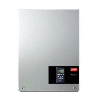
Introduction 1 Introduction This manual explains the installation and setup of the TLX Series solar inverter, for the installation technician. Illustration 1.1 Solar Inverter The TLX Series inverter range comprises the variants: TLX+ TLX Pro TLX Pro+ TLX+ TLX Pro... -
Page 6: Installation Sequence
Turn on AC at the mains switch. Set language, time, date, installed PV power, country and grid: For setup via the web interface, see the TLX Series User Manual, Web Server Quick Guide section. For setup via the display, see 3 Start-up and Check of Settings. -
Page 7: Overview Of Inverter
Terminal block for parallel connection Other Auxiliary output: Potential free relay PV load switch PELV (Safe to touch) The TLX Pro and TLX Pro+ variants can also be configured via the web interface. For further information refer to the Web Server User Manual. L00410309-09_02... -
Page 8: Installation
Installation 2 Installation 2.1 Installation Dimensions and Patterns CAUTION Follow these instructions carefully to ensure correct instal- lation of the inverter. Illustration 2.4 Ensure adequate air flow NOTE When choosing the installation place, ensure that all labels are visible at all times. For details refer to 4 Technical Data. Illustration 2.5 Mount on non-flammable surface Illustration 2.1 Avoid constant stream of water Illustration 2.6 Mount upright on vertical surface... - Page 9 Installation Illustration 2.8 Safe Distances Observe these distances when installing one or more inverters. One-row mounting is recommended. Contact the supplier for information on mounting in more rows. L00410309-09_02...
- Page 10 Installation Illustration 2.9 Wall Plate NOTE Use of the wall plate delivered with the inverter is mandatory. Use screws that can safely carry the weight of the inverter. The inverter must be aligned and it is important that the inverter is accessible at the front to allow room for servicing.
-
Page 11: Mounting The Inverter
Installation 2.2 Mounting the Inverter Lift the inverter upwards (2) over the top of the mounting plate until the inverter tilts towards the wall (3). CAUTION For safe handling of the inverter, two people must carry the unit, or a suitable transport trolley must be used. Safety boots must be worn. -
Page 12: Removing The Inverter
Installation mounting bracket (5). Check that it is not possible to lift Use a TX 30 screwdriver to loosen the two front screws. the bottom of the inverter away from the mounting Turn the screwdriver until the screws pop up. Screws are bracket. - Page 13 Installation Illustration 2.16 Close the Inverter Illustration 2.17 Fasten Front Screws To close the inverter, hold on to the lower end of the front cover with one hand and give it a tap on the top until it falls into place. Guide the front cover into place and fasten CAUTION the two front screws.
-
Page 14: Ac Grid Connection
Installation 2.5 AC Grid Connection Short-circuit bridge L1, L2, 3 mains (L1, L2, L3) and neutral (N) terminals NOTE L3, N When choosing the installation place, ensure that all labels Protective earth wire are visible at all times. For details refer to 4 Technical Data. Table 2.1 Legend to Illustration 2.19 Verify the inverter matches the grid-voltage. -
Page 15: Parallel Pv String Configuration
Installation 2.6 Parallel PV String Configuration For parallel PV string configuration, always use the internal parallel jumper, together with an external parallel coupling. Inverter Cabling PV module Illustration 2.20 Correct Parallel Connection Parallel jumper Parallel connection, 3 inputs Parallel connection, 2 inputs Table 2.2 Legend to Illustration 2.20 L00410309-09_02... - Page 16 Installation Inverter Cabling PV module Illustration 2.21 Incorrect Parallel Connection Parallel jumper Parallel connection, 1 input. Current in first input is exceeded, thus overloading cable and PV load switch. Parallel connection missing. All PV power feeds into one input, thus risking overload of PV connector, cable and PV load switch.
-
Page 17: Pv Connection
Via the display, go to [Setup → Autotest] and press OK. • Via the web interface, go to [Inverter level: Setup → Setup details → Autotest] and click on [Start → Test]. The inverter autotest manual can be downloaded from www.danfoss.com/solar. Illustration 2.22 DC Connection Area L00410309-09_02... -
Page 18: Start-Up And Check Of Settings
Start-up and Check of Setti... 3 Start-up and Check of Settings 3.1.1 Initial Setup The inverter is shipped with a predefined set of settings for different grids. All grid specific limits are stored in the inverter and must be selected at installation. It is always possible to see the applied grid limits in the display. - Page 19 Start-up and Check of Setti... Illustration 3.4 Installed PV Power Illustration 3.6 Select Grid Code Enter the amount of installed PV power for each of the PV The display will now show “Select grid”. The grid code is inputs. When two or more PV inputs are connected in set to “undefined”...
-
Page 20: Troubleshooting
PC. The master inverter is also able to replicate settings and data to the other TLX Pro and TLX L00410309-09_02... -
Page 21: Technical Data
Technical Data 4 Technical Data 4.1 General Data Nomenclat Parameter TLX Series TLX Series TLX Series TLX Series TLX Series 12.5k Rated apparent power 6000 VA 8000 VA 10000 VA 12500 VA 15000 VA 6000 W 8000 W 10000 W... - Page 22 Overload operation Change of operating point Active power control Included Reactive power control TLX+ and TLX Pro+ Table 4.1 General Specifications 1) According to FprEN 50524 where relevant. 2) At identical input voltages. At unequal input voltages, V mppmin be as low as 250 V depending on total input power.
-
Page 23: Norms And Standards
2008 und Ergänzungen von 01/2009, 07/2010, 02/2011 Spain REE BOE núm. 254 Table 4.3 Norms and Standards 1) Deviant from VDE 0126-1-1 section 4.7.1, the isolation resistance measurement limit is set to 200 kΩ, in accordance with authorities. 2) TLX+ and TLX Pro+ only. L00410309-09_02... -
Page 24: France Ute Requirements
Technical Data 4.3 France UTE Requirements Parameter Condition Specification Wall Plate Hole diameter 30 x 9 mm NOTE Alignment Perpendicular ± 5° all In France, observe the UTE C 15-712-1 and NF C 15-100 angles requirements. Table 4.5 Wall Plate Specifications For installation in France, apply warning label to front of inverter. -
Page 25: Cable Requirements
* The distance between inverter and PV array and back, plus the cumulative length of PV array cabling. Table 4.6 Cable Requirements NOTE Avoid power loss in cables greater than 1% of nominal inverter rating. 2.5 mm 4 mm 6 mm 10 mm Illustration 4.2 TLX Series 6k Cable Losses [%] versus Cable Length [m] L00410309-09_02... - Page 26 Technical Data 2.5 mm 4 mm 6 mm 10 mm Illustration 4.3 TLX Series 8k Cable Losses [%] versus Cable Length [m] 2.5 mm 4 mm 6 mm 10 mm Illustration 4.4 TLX Series 10k Cable Losses [%] versus Cable Length [m]...
- Page 27 Technical Data 4 mm 6 mm 10 mm Illustration 4.5 TLX Series 12.5k Cable Losses [%] versus Cable Length [m] 4 mm 6 mm 10 mm Illustration 4.6 TLX Series 15k Cable Losses [%] versus Cable Length [m] Consider also the following when choosing cable type and...
-
Page 28: Torque Specifications For Installation
Technical Data 4.6 Torque Specifications for Installation Illustration 4.7 Overview of Inverter with Torque Indications, 1-3 Illustration 4.8 Overview of Inverter with Torque Indications, 4-7 Parameter Tool Tightening Torque Terminal blocks (large) Straight slot 1.0 x 5.5 mm Min. 1.2 Nm Terminal blocks (small) Straight slot 1.0 x 5.5 mm 0.5 Nm... -
Page 29: Mains Circuit Specifications
Technical Data 4.7 Mains Circuit Specifications TLX Series 12.5k Maximum inverter 9.0 A 11.9 A 14.9 A 18.7 A 22.4 A current, I acmax. Recommended blow fuse type gL/ 13 A 16 A 20 A 20 A 25 A Recommended... -
Page 30: Auxiliary Interface Specifications
Technical Data 4.8 Auxiliary Interface Specifications Parameter Parameter Details Specification Serial Communication RS-485 Common cable specification Cable jacket diameter (⌀) 2 x 5-7 mm Cable type Shielded Twisted Pair (STP) (Cat 5e) Cable Characteristic Impedance 100 Ω – 120 Ω Max. - Page 31 Technical Data Parameter Parameter Details Specification Cable specification 4-8 mm Cable jacket diameter (⌀) Cable type Shielded Single Pair - 2-wire Cable shield termination Via EMC cable clamp Maximum wire gauge 2.5 mm Maximum cable length 30 m Sensor Input Specification Sensor input class Class A 12 mA for an 800 Ω...
-
Page 32: Rs-485 And Ethernet Connections
Technical Data RS485 2 x RJ45 Ethernet 2 x RJ45 Illustration 4.9 Communication Board 8-pole terminal blocks PT1000/module temp. PT1000/ambient temp. PT1000/irradiation sensor temp. Irradiation sensor S0/Energy meter Relay 1 Table 4.11 Legend to Illustration 4.9 4.9 RS-485 and Ethernet Connections RS-485 Terminate the RS-485 communication bus at both ends. - Page 33 Brown For Ethernet: 10Base-TX and 100Base-TX auto cross over Table 4.13 Legend to Illustration 4.12 Ethernet Ethernet connection is available for TLX Pro and TLX Pro+ CAUTION variants only. TLX Pro and TLX Pro+ inverters connected to the internet through Ethernet must be behind a firewall.
-
Page 34: L00410309-09_02
Danfoss can accept no responsibility for possible errors in catalogues, brochures and other printed material. Danfoss reserves the right to alter its products without notice. This also applies to products already on order provided that such alterations can be made without subsequential changes being necessary in specifications already agreed.
Need help?
Do you have a question about the TLX and is the answer not in the manual?
Questions and answers