
Related Manuals for Morgana UFO


Summary of Contents for Morgana UFO
- Page 1 FOLDING SYSTEM OPERATORS GUIDE Morgana Systems Limited United Kingdom Facsimile: ( 01908 ) 692399 Telephone: ( 0 1908 ) 608888 Website: WWW.Morgana.co.uk ISSUE 6 FEBRUARY 2005 625-001...
-
Page 2: Table Of Contents
INDEX SECTION 1: SPECIFICATION Page 2 SECTION 2: GENERAL LAYOUT Page 3 SECTION 3: SETTING UP Page 4 - side lay - side lay - operator manifold - operator.manifold - far side manifold - air knobs - shuttle valve - paper stop block - suction opening 3.10 - paper gate... - Page 3 SECTION 7: SWINGING PERFORATOR Page 14 - set up - perforating - slitting - slitting perforator - scoring - operating Perforating, slitting , scoring an main shaft SECTION 8: FOLD PLATE ADJUSTMENTS Page 18 SECTION 9: PROBLEMS AND SOLUTIONS Page 20 - fuses - electric delivery fuse SECTION 10:...
- Page 4 ECTION 1: SPECIFICATIONS MACHINE UFO 1 & 2 UFO 5 & 6 MAINS SUPPLY 220v-240v 50HZ From UFO 1 OR 2 CURRENT (Running) 9.5A 1.5A GUARDS 12VDC 12VDC FEED MOTOR 1/10 HP DC Shunt ROLLER MOTOR 375W Permanent Magnet 375W Permanent Magnet...
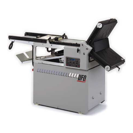
- Page 5 SECTION 2: GENERAL LAYOUT VACUUM LOADING MANIFOLDS PAPER DIGITAL SIDE FEED UPPER FOLD ROLLER TABLE GATE CONTROL POD PLATE DELIVERY SWINGING STACKER FOLD ROLLER CONVEYOR PERFORATOR TRAY SETTINGS UNIT DELIVERY WHEELS...
-
Page 6: Side Lay
SECTION 3: SETTING UP 3.1. In setting the machine for a job, it is advisable to start by positioning the side lay to a suitable position (see below). This is achieved by unscrewing the knobs (B). Lift the knobs out of their holes, and at the same time, move the side lay assembly to the desired position. -
Page 7: Far Side Manifold
The manifold should be aligned to the side lay as shown in the diagram below and also aligned equally to the scales on the loading table. Re-tighten screws (C) and (D). Place a stack of paper on the loading table and set the far side manifold to the paper size: not too tight - this will restrict the feeding not too loose - thus wasting air, giving low pile heights. -
Page 8: Shuttle Valve
Slide the shuttle valve knobs (F) to the desired position on each manifold according to paper size. The settings A2, A3 and A4 are only a guide. Obviously a very lightweight sheet of A4 will not require the same setting as, for example, a two sheet thickness of A4. -
Page 9: Paper Gate
3.10 Set the Paper Gate to the correct position. The standard setting for horizontal adjustment of the Paper Gate is 1Omm (3/8") away from the mounting block. Turn disc J to make this adjustment. This setting is only intended as a guide, for instance, sheets with an upward curl will require this setting to be increased. -
Page 10: Setting Of Fold Plates
3.14 Setting of fold plates. Set the fold length by releasing the lock knob (H) and rotating the dial (J). Press the 'ON' button on the fold plate, the fold length can then be read off the display (K). More precise movements can be made by pressing the 'Micro' button, which will display increments of one tenth of a millimetre or one hundreth of an inch for imperial machines. - Page 11 UFO FOLDER QUICK START CHART FOLD PLATE PAPER SIZE ROLLER SETTING TYPE POSN BACK BOTTOM BOTTOM LETTER BOTTOM CONCERTINA BOTTOM HALF BOTTOM DOUBLE PARALLEL BOTTOM GATE BOTTOM ENGINEERING SIZE SRA2 & ABOVE SWITCH 1 / 2 2/3/4 4/5/6 6/7/8 8 / 9...
-
Page 12: Batching
THE CONTROL POD DISPLAY THE DIAGRAM BELOW SHOWS THE UFO DIGITAL DISPLAY. WITH THE MOTORS, FEEDER AND AIR OFF, OPERATE THE MODE SWICH UNTIL THE SPACING LAMP IS ON. THE IN- FORMATION IN THE DISPLAY NOW REPRESENTS: VACUUM - THE VACUUM ‘ON’ TIME. VARIABLE BETWEEN 25%(1/4) AND 80%(13/16) OF THE SHEET LENGTH IN 12.5% (1/8) INCREMENTS. - Page 13 SETTING THE BATCH QUANTITY PRESS THE MODE SWITCH UNTIL THE BATCH LAMP IS ON. ROTATE THE VALUE DIAL TO DETERMINE THE BATCH SIZE. RUNNING THE MACHIHE ONCE ALL OF THE PREVIOUS SETTINGS HAVE BEEN ADJUSTED THE MACHINE IS READY TO START FOLDING. WHILST THE MACHINE IS IN OPERATION, THE DISPLAY CAN EITHER SHOW THE RATE AT WHICH THE SHEETS ARE BEING FOLDED (SHEETS PER HOUR) OR SHOW THE TOTAL AMOUNT OF FOLDED DOCUMENTS.
- Page 14 THE POWER LEAD FOR CONTROLLER PLUGS INTO THE SOCKET LOCATED ON THE REAR PANEL OF THE UFO. THE DELIVERY CONVEYOR MAYBE REMOVED FROM THE UFO AFTER FIRST DISCONNECTING THE POWER SUPPLY CABLE FROM THE SOCKET AND RAISING THE KNOBS ‘R’. TAKE THE...
- Page 15 A short extension delivery (part no. L59) is available and may be used in any position. When used beneath the UFO, the standard delivery can be used to extend the delivery point to beyond the UFO loading table.
-
Page 16: Perforating
SECTION 7: SWINGING PERFORATOR UNIT To use the unit, first remove the second fold plate, see page 7. To set up for perforating, scoring, slitting Fit the appropriate blade, blades or scorers onto the shafts in the approximate sideways position as described in sections 7.3, 4, 5 and 6. For easier access to the shafts, it is necessary to first remove the two thumb screws at each end of the swing up cover, and remove the central knob. -
Page 17: Slitting
Slitting The slitting set (part number 1-99-13P) consists of two blades which have been split in half. Before fitting, ensure that the side faces of the hubs are clean. Using the screws provided, mount them to the hubs as shown, and line the blades up to the job as described on page 14. -
Page 18: Slitting Perforator
Slitting Perforator Slitting Perforators are installed onto the shafts in the same way as the Slitters, but use an anvil on the bottom shaft instead of another blade. UPPER OUTPUT SHAFT PERFORATING BLADE UPPER TYRE AND HUB ASSEMBLIES 1,0 mm 1,0 mm ( 3/64") ( 3/64") -
Page 19: Operating
Type A A square section scorer which will produce a light score on Part No.6-99-05P most card. Standard It should be set centrally between the faces of two perforator hubs set approximately 1mm or 3/64 inch apart. Type B A square section scorer which is suitable for use on heavy Part No.6-99-06P card. - Page 20 7.8 Perforating, Scoring and Slitting on Main Perforator Shafts To gain access to the main perforator shafts, lift up the feed bed (which is only held in place by a magnetic catch), and also the top cover. The standard hubs, which are factory fitted only, allow for a single perforator, scorer or slitter at this position.
- Page 21 Adjustments 1 and 2 With the fold plate removed from the machine, slide out the lower cover. Release the locking screw (X) with a 3mm allen key. Adjustment 1 continued The adjusting screws (Y), one each side, located through a spring, may now be turned using a 4mm allen key until the lower rail is at the desired position.
-
Page 22: Fuses
SECTION 9: PROBLEMS AND SOLUTIONS It must be remembered that many problems occur due to incorrect or badly adjusted settings and that the instructions found in this book will help resolve them. 9.1 Fuses If any malfunction occurs, always check the fuses before taking any other action. -
Page 23: General
Installation The crossfold’s simply plugs into the auxiliary output socket in the rear panel of the UFO, with no other connections. The electric delivery, when fitted to a crossfold unit, is plugged into the auxiliary socket on the crossfold’s rear panel. -
Page 26: Changing The Lay Side
10.3 Changing the Lay Side on the Crossfold 1. Remove locking knob (a) and M5 cap screws (2 off ) (b) with 4mm allen key provided and lift side lay away. 2. Raise guard (c), lift the roller bed at the front and support it on its prop. -
Page 27: Sheet Detector
SECTION 11: MAINTENANCE 11.1 Sheet Detector This detector is the sensor for the batch and total counter, and is as shown. Some machines have their reflector plate fixed to the papergate. Reflector plate The sensor operates from an infra-red beam reflected off the reflector plate. The position of this reflector is factory set and must not be disturbed. -
Page 28: Regular Maintenance
11.2 Regular Maintenance The UFO Folding Machine has been designed for minimum maintenance; however, the following items will need attention. Weekly - The two roller shafts on the feed bed should be cleaned and sparingly oiled (see page 37, items 50 and 60 of the spare parts manual). -
Page 29: Motor Speeds
Not feeding efficiently Size control at wrong setting (see page 11). Paper gate in wrong Position (see page 7). Slot in vacuum drum in wrong position (see page 6). Manifold set incorrectly (see page 5). Manifold settings incorrect (see page 5). Sheets creasing Side lay balls too heavy.
Need help?
Do you have a question about the UFO and is the answer not in the manual?
Questions and answers